PN3642_D26Z中文资料
安全继电器PNOZX-急停按钮安全门和光栅-技术特性

安全继电器PNOZ X -急停按钮、安全门和光栅- 技术特性下载374281PNOZ X Set plugin screw terminalsP3+P4374282PNOZ X Set plug in screwterminalsP5+P5PNOZ X9P 24DC 24-240VACDC 7no 2nc 2so产品物料号: 777606PNOZ X 安全继电器的可靠性和可用性已经得到验证。
在各种安全应用中,都能找到PNOZ X 安全继电器。
每个安全功能,都使用一个PNOZ X。
其技术特点是基于继电器技术中的通用电压机电式触点。
尺寸从22.5 到90 mm 不等,触点数量为2 到8 个不等。
无论您的安全需求是什么,PNOZ X 一定是您适合的解决方案Pilz 773050 PNOZmulti Systemhandbuch DPilz 773100 PNOZ m1p base unitPilz773105 PNOZ m1p base unit coated versionPilz773110 PNOZ m0p base unit not expandablePilz 773120 PNOZ m2p base unit press functionPilz 773200 PNOZ pps1p 100-240VACPilz 773300 PNOZ p1p 24VDC 2soPilz 773400 PNOZ mi1p 8 inputPilz 773405 PNOZ mi1p 8 inputs coated versionPilz 773410 PNOZ mi2p 8 standard inputPilz 773500 PNOZ mo1p 4 soPilz 773505 PNOZ mo1p 4so coated versionPilz 773510 PNOZ mo3p 2soPilz 773520 PNOZ mo2p 2n/oPilz 773525 PNOZ mo2p 2n/o coated versionPilz 773536 PNOZ mo4p 4n/oPilz 773537 PNOZ mo4p 4n/o coated versionPilz 773540 PNOZ ml1p safe linkPilz 773630 PNOZ po3.1p 8n/oPilz 773631 PNOZ po3.2p 4n/oPilz 773632 PNOZ po3.3p 3n/oPilz 773634 PNOZ po3p 3n/o 1n/cPilz 773635 PNOZ po4p 4n/oPilz 773700 PNOZ mc1pPilz 773705 PNOZ mc1p coated versionPilz 773720 PNOZ mc0p PowersupplyPilz 773721 PNOZ mc3p ProfibusPilz 773722 PNOZ mc4p DeviceNetPilz 773723 PNOZ mc5p INTERBUSPilz 773724 PNOZ mc6p CANopenPilz 773725 PNOZ mc7p CC-Link coated versionPilz 773726 PNOZ mc7p CC-LinkPilz 773727 PNOZ mc6p CANopen coated versionPilz 773728 PNOZ mc5.1p Interbus LWL / FiberopticPilz 773729 PNOZ mc4p DeviceNet coated versionPilz 773730 PNOZ mc8p Ethernet IP / Modbus TCPPilz 773731 PNOZ mc9p Profinet IOPilz 773800 PNOZ ms1p standstill / speed monitorPilz 773810 PNOZ ms2p standstill / speed monitorPilz 773812 PNOZ ma1p 2 Analog InputPilz 773839 PNOZ msi1Bp Adapter Si/Ha 25/25 5mPilz 773840 PNOZ msi1Ap Adapter Si/Ha 25/25 2,5mPilz 773841 PNOZ msi1Bp Adapter Si/Ha 25/25 2,5mPilz 773842 PNOZ msi3Ap Adapter Si/Ha 15/15 2,5mPilz 773843 PNOZ msi3Bp Adapter Si/Ha 15/15 2,5mPilz 773850 PNOZ msi1p Adapter Si/Ha 25/25 2,5mPilz 773844 PNOZ msi1AP Adapter Si/Ha 25/25 5mPilz 773854 PNOZ msi10p adapter cable 2,5mPilz 773855 PNOZ msi11p adapter cable 1,5mPilz 773856 PNOZ msi 9p adapter cable 5mPilz 773857 PNOZ msi5p Adapter Bos/Rex 15/15 2,5mPilz 773858 PNOZ msi5p Adapter Bosc/Rex 15/15 1,5m Pilz 773859 PNOZ msi6p Adapter Elau 9/9 7,5mPilz 773860 PNOZ msi6p Adapter Elau 9/9 2,5mPilz 773861 PNOZ msi6p Adapter Elau 9/9 1,5mPilz 773862 PNOZ msi8p Adapter Lenze 9/9 2,5mPilz 773863 PNOZ msi8p Adapter Lenze 9/9 1,5mPilz 773864 PNOZ msi7p Adapter SEW 15/15 2,5mPilz 773865 PNOZ msi7p Adapter SEW 15/15 1,5mPilz 773867 PNOZ msi16p ADAPTER Baumuell 15/15 2,5m 773868 PNOZ msi12p Rockwell 15/15 2,5m773869 PNOZ msi13p Fanuc 20/20 2,5m773870 PNOZ msi S09773871 PNOZ msi S15773872 PNOZ msi S25773874 PNOZ msi15p Adapter Tendo 15/15 2,5m773875 PNOZ msi17p Bos/Rex 15/15 4,0m773878 PNOZ msi14p Leroy 15/15 2,5m773880 PNOZ msi b1 Box 15p773881 PNOZ msi b0 cable 15/RJ45773882 PNOZ msi b1 Box 9p773883 PNOZ msi b1 Box 25p773884 PNOZ msi b0 cable 25/RJ45 773890 PNOZ mli1p 5m screw773891 PNOZ mli1p 10m screw773892 PNOZ mli1p 50m screw773893 PNOZ mli1p 5m spring773894 PNOZ mli1p 10m spring773895 PNOZ mli1p 50m spring773900 PNOZ pe1p773950 PNOZ p1vp 30s773951 PNOZ p1vp 300s774000 PNOZ 10 24VAC 6n/o 4n/c 774001 PNOZ 10 42VAC 6n/o 4n/c 774002 PNOZ 10 48VAC 6n/o 4n/c 774003 PNOZ 10 110-120VAC 6n/o 4n/c 774006 PNOZ 10 230-240VAC 6n/o 4n/c 774009 PNOZ 10 24VDC 6n/o 4n/c 774012 PNOZ 2VJ 24VDC 3n/o 1n/c 2n/o t 774013 PNOZ 2VQ 24VDC 3n/o 1n/c 2n/o t 774015 PZW 30/110-120VAC 1n/o 2n/c 774017 PZW 30/230VAC 1n/o 2n/c 774019 PZW 30/24VDC 1n/o 2n/c774020 PZA 300/24VAC 1n/o 2n/c 774021 PZA 300/42VAC 1n/o 2n/c 774023 PZA 300/110-120VAC 1n/o 2n/c 774026 PZA 300/230VAC 1n/o 2n/c 774028 PZA 600/24VDC 1n/o 2n/c 774029 PZA 300/24VDC 1n/o 2n/c 774030 PZA 30/24VDC 1n/o 2n/c774031 PZA 30/24VAC 1n/o 2n/c774035 PZA 30/110-120VAC 1n/o 2n/c 774038 PZA 3/230VAC 1n/o 2n/c774040 PZA 30/230VAC 1n/o 2 n/c 774041 PZA 3/24VDC 1n/o 2n/c774042 PZW 3/24VDC 1n/o 2n/c774044 PZW 3/110-120VAC 1n/o 2n/c 774048 PZW 3/230VAC 1n/o 2n/c774049 PNOZ X7 48VAC 2n/o774050 PNOZ 15 24VDC 3n/o 1n/o 1n/c 774051 PNOZ X7.1 24VAC/DC 1n/o 1n/c 774053 PNOZ X7 110VAC 2n/o774054 PNOZ X7 115VAC 2n/o774055 PNOZ X7 120VAC 2n/o774057 PNOZ X7 240VAC 2n/o774058 PNOZ X7 42VAC 2n/o774059 PNOZ X7 24VACDC 2n/o774060 PNOZ 16 24VAC 24VDC 2n/o774061 PNOZ 16 42VAC 24VDC 2n/o774062 PNOZ 16 48VAC 24VDC 2n/o774063 PNOZ 16 110VAC 24VDC 2n/o774064 PNOZ 16 115VAC 24VDC 2n/o774065 PNOZ 16 120VAC 24VDC 2n/o774066 PNOZ 16 230VAC 24VDC 2n/o774067 PNOZ 16 240VAC 24VDC 2n/o774070 PNOZ 16S 24VAC 24VDC 2n/o 2so 774071 PNOZ 16S 42VAC 24VDC 2n/o 2so 774072 PNOZ 16S 48VAC 24VDC 2n/o 2so 774073 PNOZ 16S 110VAC 24VDC 2n/o 2so 774074 PNOZ 16S 115VAC 24VDC 2n/o 2so 774075 PNOZ 16S 120VAC 24VDC 2n/o 2so 774076 PNOZ 16S 230VAC 24VDC 2n/o 2so 774077 PNOZ 16S 240VAC 24VDC 2n/o 2so 774080 PNOZ 11 24VAC 24VDC 7n/o 1n/c 774081 PNOZ 11 42VAC 24VDC 7n/o 1n/c 774082 PNOZ 11 48VAC 24VDC 7n/o 1n/c 774085 PNOZ 11 110-120VAC 24VDC 7n/o 1n/c 774086 PNOZ 11 230-240VAC 24VDC 7n/o 1n/c 774090 SCHUTZKAPPE P-93 (VE 20 St.) 774100 PNOZ EX 230VAC 3n/o 1n/c774104 PNOZ EX 115VAC 3n/o 1n/c774105 PNOZ EX 120VAC 3n/o 1n/c774106 PNOZ EX 115VAC 3n/o 1n/c FM/USA 774107 PNOZ EX 120VAC 3n/o 1n/c FM/USA 774108 PNOZ EX 230VAC 3n/o 1n/c FM/USA 774120 PNOZ K2.1 24VDC 2n/o Sonderger?t 774125 P2HZ K3 24VDC 2n/o 1n/c Ger?t o. CE 774130 PNOZ e1p 24VDC 2so774131 PNOZ e1vp 10/24VDC 1so 1so t 774132 PNOZ e1vp 300/24VDC 1so 1so t 774133 PNOZ e1.1p 24VDC 2so774135 PNOZ e2.2p 24VDC 2so774136 PNOZ e2.1p 24VDC 2so774137 PNOZ e3vp 10/24VDC 1so 1so t 774138 PNOZ e3vp 300/24VDC 1so 1so t 774139 PNOZ e3.1p 24VDC 2so774140 PZE 9 24VAC 8n/o 1n/c774142 PZE 9 48VAC 8n/o 1n/c774143 PZE 9 110-120VAC 8n/o 1n/c774144 PZE 9 120 Vac 8n/o 1n/c774148 PZE 9 230-240VAC 8n/o 1n/c774150 PZE 9 24VDC 8n/o 1n/c774180 PNOZ e4.1p 24VDC 2so774181 PNOZ e4vp 10/24VDC 1so 1so t774190 PNOZ e5.11p 24VDC 2so774191 PNOZ e5.13p 24VDC 2so774192 PNOZ e6.1p 24VDC 4n/o 2so774193 PNOZ e6vp 24VDC 4n/o 1so 1so t 774195 Terminal block filter 1774196 Terminal block filter 2774300 PNOZ X1 24VAC/DC 3n/o 1n/c774303 PNOZ X2 24VAC/DC 2n/o774304 PNOZ X2C 24VAC/DC 2n/o774305 PNOZ X2.1C 24VAC/DC 2n/o774306 PNOZ X2.1 24VAC/DC 2n/o774309 PNOZ X3.2 230VAC 24VDC 3n/o 1n/c 1so 774310 PNOZ X3 24VAC 24VDC 3n/o 1n/c 1so 774311 PNOZ X3 42VAC 24VDC 3n/o 1n/c 1so 774312 PNOZ X3 48VAC 24VDC 3n/o 1n/c 1so 774314 PNOZ X3 110VAC 24VDC 3n/o 1n/c 1so 774315 PNOZ X3 115VAC 24VDC 3n/o 1n/c 1so 774316 PNOZ X3 120VAC 24VDC 3n/o 1n/c 1so 774318 PNOZ X3 230VAC 24VDC 3n/o 1n/c 1so 774319 PNOZ X3 240VAC 24VDC 3n/o 1n/c 1so 774321 PNOZ X3.1 230VAC 24VDC 3n/o 1n/c 1so 774322 PNOZ X3.1 240VAC 24VDC 3n/o 1n/c 1so 774323 PNOZ X5J 24VDC 2n/o774324 PNOZ X5.1 24VDC 2n/o774325 PNOZ X5 24VACDC 2n/o774326 PNOZ X5 12VDC 2n/o774327 PNOZ X5 12VDC 2n/o coated version 774330 P2HZ X1 24VAC 3n/o 1n/c774331 P2HZ X1 42VAC 3n/o 1n/c774332 P2HZ X1 48VAC 3n/o 1n/c774340 P2HZ X1 24VDC 3n/o 1n/c774341 P2HZ X1 26VDC 3n/o 1n/c774345 P2HZ X2 24VAC 2n/o774350 P2HZ X3 24VDC 2n/o 1n/c774360 P1HZ X1 24VDC 2n/o774400 PDZ 24VDC 2n/o 2n/c774401 PAD/BO 512/6/5VDC774402 PAD/SI 800/512I/5VDC774403 PAD/SI 800/1024I/5VDC774404 PAD/SI 800/2048I/5VDC774405 PAD/SI 800/4096I/5VDC774406 PAD/SI 840/512I/5VDC774407 PAD/SI 840/1024I/5VDC774408 PAD/SI 840/2048I/5VDC774409 PAD/SI 840/4096I/5VDC774410 PAD/SI 800/32I/5VDC774411 PAD/SI 840/256I/5VDC774412 PAD/SI 840/128I/5VDC774413 PAD/SI 840/64I/5VDC774414 PAD/SI 840/32I/5VDC774415 PAD/SI 840/16I/5VDC774420 PDZK WDP3-01 1000/20 24 Vdc774434 P2HZ X1 110VAC 3n/o 1n/c774435 P2HZ X1 115VAC 3n/o 1n/c774436 P2Z X1 120VAC 3n/o 1n/c774438 P2HZ X1 230VAC 3n/o 1n/c774439 P2HZ X1 240VAC 3n/o 1n/c774500 PNOZ XV2 30/24VDC 2n/o 2n/o t774502 PNOZ XV2 3/24VDC 2n/o 2n/o t774504 PNOZ XV2 0.5/24VDC 2n/o 2n/o fix 774505 PNOZ XV2 3/24VDC 2n/o 2n/o fix774506 PNOZ XV2 10/24VDC 2n/o 2n/o fix774508 PNOZ XV2 300/24VDC 2n/o 2n/o t774510 PNOZ XV2.1 30/24VAC 24VDC 2n/o 2n/o t 774515 PNOZ XV2.1 30/120VAC 24VDC 2n/o 2n/o t 774516 PNOZ XV2.1 30/230VAC 24VDC 2n/o 2n/o t 774517 PNOZ X2.4V 1/24VDC 4n/o 1so fix774520 PNOZ XV2.1 3/24VAC 24VDC 2n/o 2n/o t 774524 PNOZ XV2.1 3/115VAC 24VDC 2n/o 2n/o t 774525 PNOZ XV2.1 3/120VAC 24VDC 2n/o 2n/o t 774526 PNOZ XV2.1 3/230VAC 24VDC 2n/o 2n/o t 774530 PNOZ XV3.1 30/24VDC 3n/o 1n/c 2n/o t 774532 PNOZ XV3.1 3/24VDC 3n/o 1n/c 2n/o t 774534 PNOZ XV3.1 0.5/24 Vdc 3n/o 1n/c 2n/o fix 774536 PNOZ XV2.1 0.5/230 Vac 24 Vdc 2n/o 2n/o f 774538 PNOZ XV3.1 300/24VDC 3n/o 1n/c 2n/o t 774540 PNOZ XV3 30/24VDC 3n/o 2n/o t774541 PNOZ XV3 300/24VAC 3n/o 2n/o t774542 PNOZ XV3 3/24VDC 3n/o 2n/o t。
西门子CPU 226技术参数

CPU 226 CN 技术数据物理特性尺寸 (W X H X D) 重量功耗196 x 80 x 62 mm550 g11 W196 x 80 x 62 mm660 g17 W程序存储器在线程序编辑时非在线程序编辑时数据存储器装备(超级电容) (可选电池) 16384 bytes24576 bytes10240 bytes100小时/典型值(40°C时最少70小时)200天/典型值16384 bytes24576 bytes10240 bytes100小时/典型值(40°C时最少70小时)200天/典型值本机数字量输入本机数字量输出本机模拟量输入本机模拟量输出数字I/O映象区模拟I/O映象区允许最大的扩展I/O模块允许最大的智能模块脉冲捕捉输入高速计数器总数单相计数器两相计数器脉冲输出24 输入16 输出无无256 (128输入/128输出)64(32输入/32输出)7个模块7个模块246个6,每个30KHz4,每个20KHz2个20KHz(仅限于DC输出)24 输入16 输出无无256 (128输入/128输出)64(32输入/32输出)7个模块7个模块246个6,每个30KHz4,每个20KHz2个20KHz(仅限于DC输出)定时器总数1ms10ms 100ms计数器总数256个4个16个236个256(由超级电容或电池256个4个16个236个256(由超级电容或电池内部存储器位掉电保持时间中断边沿中断模拟电位器布尔量运算执行时间时钟卡件选项备份)256(由超级电容或电池备份)112(存储在EEPROM)2个1ms分辨率4个上升沿和/或4个下降沿 2个8位分辨率0.22μs内置存储卡和电池卡备份)256(由超级电容或电池备份)112(存储在EEPROM)2个1ms分辨率4个上升沿和/或4个下降沿 2个8位分辨率0.22μs内置存储卡和电池卡接口PPI/T波特率自由口波特率每段最大电缆长度最大站点数最大主站数点到点(PPI主站模式)MPI连接2个RS-485接口9.6,19.2和187.5kbaud1.2kbaud 至115.2kbaud使用隔离的中继器:187.5kbaud可达1000米,38.4kbaud可达1200米未使用隔离中继器:50米每段32个站,每个网络126个站32是(NETR / NETW)共4个,2个保留(1个给PG,1个给OP)2个RS-485接口9.6,19.2和187.5kbaud1.2kbaud 至115.2kbaud使用隔离的中继器:187.5kbaud可达1000米,38.4kbaud可达1200米未使用隔离中继器:50米每段32个站,每个网络126个站32是(NETR/ NETW)共4个,2个保留(1个给PG,1个给OP)输入电源输入电压输入电流冲击电流隔离(现场与逻辑) 20.4至28.8V DC150mA (仅CPU,24V DC)1050mA (最大负载,24V DC)12A,28.8V DC时85至264 V AC(47至63 Hz)80/40mA(仅CPU,120/240V AC)320/160mA(最大负载,120/240V AC)保持时间(掉电) 保险(不可替换) 不隔离10ms,24V DC时3A,250V时慢速熔断20A,264V AC时1500V AC20/80ms,120/240V AC时2A,250V时慢速熔断传感器电压电流限定纹波噪声隔离(传感器与逻辑) L+减5V1.5A峰值,终端限定非破坏性来自输入电源非隔离20.4至 28.8 VDC1.5A峰值,终端限定非破坏性小于1 V峰分值非隔离本机集成数字量输入点数输入类型额定电压最大持续允许电压浪涌电压逻辑1信号 (最小) 逻辑0信号 (最大) 输入延迟连接2线接近开关传感器(Bero)允许漏电流最大隔离(现场与逻辑) 光电隔离隔离组高速输入速率高速计数器逻辑1=15 – 30V DC高速计数器逻辑1=15 – 26V DC同时接通的输入电缆长度最大屏蔽非屏蔽24输入漏型/源型 (IEC 类型1/漏型)24V DC,4mA典型值时30V DC35V DC,0.5秒15V DC,2.5mA5V DC,1mA可选(0.2至12.8ms)1mA是500V AC,1分钟见接线图20KHz(单相),10KHz(两相)30KHz(单相),20KHz(两相)500米(标准输入)24输入漏型/源型 (IEC 类型1/漏型)24V DC,4mA典型值时30V DC35V DC,0.5秒15V DC,2.5mA5V DC,1mA可选(0.2至12.8ms)1mA是500V AC,1分钟见接线图20KHz(单相),10KHz(两相)30KHz(单相),20KHz(两相)500米(标准输入)50米(高速计数器输入)300米(标准输入) 50米(高速计数器输入)300米(标准输入)本机集成数字量输出点数输出类型额定电压电压范围浪涌电流(最大) 逻辑1(最小)逻辑0(最大)每点额定电流(最大)每个公共端的额定电流(最大)漏电流(最大)灯负载(最大)感性嵌位电压接通电阻(接点) 隔离光电隔离(现场到隔离)逻辑到接点电阻(逻辑到接点) 隔离组16输出固态 - MOSFET(源型)24 VDC20.4至 28.8V DC8A,100ms20V DC,最大电流0.1V DC,10KΩ 负载0.75A6 A10μA5 WL+ 减48VDC,1W功耗0.3 Ω典型值(0.6Ω最大值)500 VAC,1分钟--见接线图16输出干触点24V DC或250V AC5至30V DC或5至250V AC5A,4s (10%工作率时)--2.0A10A-30W DC;200 W AC-0.2Ω(新的时候最大值)-1500V AC,1分钟100 MΩ见接线图延时(最大)断开到接通接通到断开切换脉冲频率(最大) 机械寿命周期触点寿命同时接通的输出两个输出并联2μs(Q0.0, Q0.1),15μs(其它)10μs(Q0.0,Q0.1),130μs(其它)-20KHz(Q0.0和Q0.1)--55°C时,所有的输出(水平安装)--10ms1Hz10,000,000(无负载)100,000(额定负载)55°C时,所有的输出(水平)45°C时,所有的输电缆长度(最大) 屏蔽非屏蔽45°C时,所有的输出(垂直安装)是,仅输出同组时500米150米出(垂直)否500米150米。
E4.2N 4000 Ekip Touch LI 三极固定三极针电流保护器产品说明书

Rated Uninterrupted Current (Iu) Release Release Type Short-Circuit Performance Level Standards
Not Available 1SDH001000R0002 1SDH001316R1002
Classifications
ETIM 4 ETIM 5 ETIM 6 ETIM 7
Object Classification Code WEEE Category
EC000228 - Power circuit-breaker for trafo/generator/installation prot. EC000228 - Power circuit-breaker for trafo/generator/installation prot. EC000228 - Power circuit-breaker for trafo/generator/installation prot.
for 1 s 66 kA for 3 s 50 kA (400 V AC) 66 kA (415 V AC) 66 kA (440 V AC) 66 kA (500 V AC) 66 kA (525 V AC) 66 kA (690 V AC) 66 kA
4000 A
Ekip Touch LI EL N
8015644750442 1 piece
8ห้องสมุดไป่ตู้362090
384 mm 371 mm 270 mm
NF前后门培训

通过PROFINET的同步实时(IRT)功能,可以轻松实现对伺服运动控制系统的 控制。 在PROFINET同步实时通讯中,每个通讯周期被分成两个不同的部分,一个是 循环的、确定的部分,称之为实时通道;另外一个是标准通道,标准的TCP/IP数据通 过这个通道传输。
在实时通道中,为实时数据预留了固定循环间隔的时间窗,而实时数据总是按固 定的次序插入,因此,实时数据就在固定的间隔被传送,循环周期中剩余的时间用来 传递标准的TCP/IP数据。两种不同类型的数据就可以同时在PROFINET上传递,而且 不会互相干扰。通过独立的实时数据通道,保证对伺服运动系统的可靠控制。
自从PROFIBUS作为首例的现场总线在中国的国家标准(GB/T 20540.1-2006GB/T20540.6-2006)中达到最高等级之后,中国标准化机构也给予了PROFINET以GB/Z 类指导标准的地位。因此与其它以太网标准相比,PROFINET在中国拥有最高的标准化 等级。在标准化活动方面所取得的成功为PROFINET技术在未来更加迅速传播打下坚实 的基础。前所未有的方式实现全面流畅的通讯,可明显降低调试、维护、诊断、运行以 及备件服务方面的成本。焊装车间采用PROFINET和基于组件的自动化技术,明显加快 设备的调试进程。
通过模块化这一成功理念,可以显著降低机器和工厂建设中的组态与上线调试时 间。在使用分布式智能系统或可编程现场设备、驱动系统和I/O时,还可以扩展使用模 块化理念,从机械应用扩展到自动化解决方案。另外,也可以将一条生产线的单个机 器作为生产线或过程中的一个"标准模块"进行定义。作为设备与工厂设计者,工艺模 块化能够更容易、更好地对您的设备与系统进行标准化和再利用。使您能够对不同的 客户要求更快、更具灵活性地作出反应。您可以对各台设备和厂区提前进行预先测试-极大地缩短系统上线调试阶段。作为系统操作者,从现场设备到管理层,你都可以从 IT标准的通用通讯中获得好处。对现有系统进行扩展也很容易。
PCS-9655_X_说明书_国内中文_国内标准版_X_R1.21
1.1 应用 ................................................................................................................................ 1
1.2 功能 ................................................................................................................................ 1
南京南瑞继保电气有限公司
技术支持,请联系: 电话:025-52107703、8008289967、4008289967 传真:025-52100770 或登陆网站:/ser_sup
公司地址:中国南京江宁区苏源大道 69 号 邮编:211102 公司网址:
我们对本文档及其中的内容具有全部的知识产权。除非特别授权,禁止复制或向第三方分发。凡侵犯本公司版权等知识产权的,本公司必 依法追究其法律责任。 我们定期仔细检查本文档中的内容,在后续版本中会有必要的修正。但不可避免会有一些错误之处,欢迎提出改进的意见。 我们保留在不事先通知的情况下进行技术改进的权利。
2.3 管理功能参数.................................................................................................................. 9
2.3.1 时钟性能参数....................................................................................................... 9
电磁保护设备TeSys GV系列产品参数表说明书
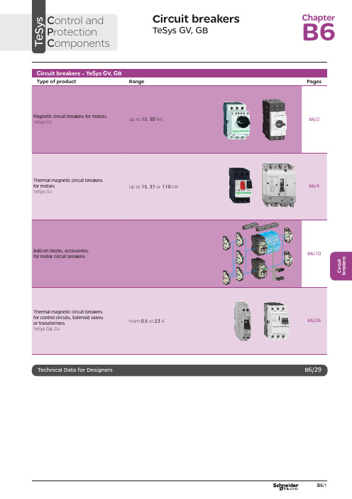
C i r c u i t b r e a k e r sCircuit breakersTeSys GV, GBC ontrol and P rotection C omponentsChapterB60.75g g 1.1g g 1.5375 2.533.5 LR2 K0308GV2LE071.1g g –––––– 2.533.5 LR2 K0308GV2LE071.5g g 1.5g g 3375451 LR2 K0310GV2LE08––– 2.2g g –––451 LR2 K0312GV2LE082.2g g 3501004375 6.378 LR2 K0312GV2LE103g g 410100 5.537510138 LR2 K0314GV2LE144g g 5.510100–––10138 LR2 K0316GV2LE14––––––7.537510138 LRD 14GV2LE14––––––937514170 LRD 16GV2LE165.515507.56751137514170 LR2 K0321GV2LE167.5155096751537518223 LRD 21GV2LE20915401147518.537525327 LRD 22GV2LE2211154015475–––25327 LRD 22GV2LE2215105018.54752237532416LRD 32GV2LE32(1) As % of Icu.g ) > 100 kA.GV2 LE10D F 526144.t i fC i r c u i t b r e a k e r s0.09––––––0.45LRD 03GV2L030.12g g –––0.37g g 0.638LRD 04GV2L040.18g g ––––––0.638LRD 04GV2L04––––––0.55g g 113LRD 05GV2L050.25g g ––––––113LRD 05GV2L05––––––0.75g g 113LRD 06GV2L050.37g g 0.37g g –––113LRD 05GV2L050.55g g 0.55g g 1.1g g 1.622.5LRD 06GV2L06–––0.75g g ––– 1.622.5LRD 06GV2L060.75g g 1.1g g 1.54100 2.533.5LRD 07GV2L07Example: GV3 L32 becomes GV3 L326.(1) As % of Icu. Associated current limiter or fuses, where required. See characteristics page B6/33.g > 100 kA.GV2 L10D F 526145.t i fGV3 L65D F 526146.t i fTeSys GVThermal-magnetic motor circuit breakers GV2 ME0.06gg––––––0.16…0.252.4GV2ME020.09g g––––––0.25…0.405GV2ME030.12 0.18g g g g – –– –– – 0.37 –g–g –0.40…0.638GV2ME040.25gg––– 0.55gg0.63…113GV2ME050.37 0.55 –g g –g g –0.37 0.55 0.75g g g g g g – 0.75 1.1– g g – g g 1…1622.5GV2ME060.75g g1.1gg1.5375 1.6...2.533.5GV2ME071.1 1.5g g g g 1.5 2.2g g g g 2.2 3 3 375 75 2.5 (4)51GV2ME082.2gg350100 43754...6.378GV2ME103 4g g g g 4 5.510 10100 100 5.5 7.5 3 375 756 (10)138GV2ME145.5 –15 –50 –7.5 – 6 –75 – 9 11 3 375 759…14170GV2ME167.5155096751537513…18223GV2ME209154011475 18.537517…23327GV2ME2111154015475 –––20…25327GV2ME22 (3)15105018.54752237524 (32)416GV2ME32Motor circuit breakers from 0.06 to 15 kW / 400 V, with lugsTo order thermal magnetic circuit breakers with connection by lugs, add the digit 6 to the end of reference selected above.Example: GV2 ME08 becomes GV2 ME086.Thermal magnetic circuit breakers GV2 ME with built-in auxiliary contact block With instantaneous auxiliary contact block (composition, see page B6/11):b GV AE1, add suffix AE1TQ to the motor circuit breaker reference selected above. Example: GV2 ME01AE1TQ .b GV AE11, add suffix AE11TQ to the motor circuit breaker reference selected above. Example: GV2 ME01AE11TQ .b GV AN11, add suffix AN11TQ to the motor circuit breaker reference selected above. Example: GV2 ME01AN11TQ .These circuit breakers with built-in contact block are sold in lots of 20 units in a single pack.(1) As % of Icu.(2) The thermal trip setting must be within the range marked on the graduated knob.(3) Maximum rating which can be mounted in enclosures GV2 MC or MP , please consult your Regional Sales Office. g > 100 kA.GV2 ME10D F 526134.t i fC i r c u i t b r e a k e r sTeSys GVTeSys protection componentsThermal-magnetic motor circuit breakers GV2 MEReferences0.06g g ––– 0.16…0.25 2.4GV2ME0230.09g g ––– 0.25…0.405GV2ME0330.120.18g g g g –––0.40…0.638GV2ME0430.250.37g g g g 0.37g g 0.63…113GV2ME0530.370.55g g g g 0.370.550.75g g g g g g 1…1.622.5GV2ME0630.75g g1.1g g 1.6…2.533.5GV2ME0731.11.5g g g g 1.52.2g g g g 2.5…451GV2ME0832.2g g 350100 4…6.378GV2ME10334g g g g 45.510101001006…10138GV2ME1435.515507.5675 9…14170GV2ME1637.515509675 13…18223GV2ME203911151540401147517…23327GV2ME2131115401547520 (25)327GV2ME223Contact blocksDescription Mounting Maximum number Type of contacts Sold in lots of Unitreference Instantaneous auxiliary contactsFront 1N/O + N/C 10GVAE113N/O + N/O 10GVAE203LH side2N/O + N/C 1GVAN113N/O + N/O1GVAN203AccessoryDescriptionApplicationSold in lots of Unitreference Cable end reducerFor connection of conductors from 1 to 1.5 mm 220LA9D99(1) For connection of conductors from 1 to 1.5 mm 2, the use of an LA9 D99 cable end reducer is recommended.(2) Maximum rating which can be mounted in enclosures GV2 MC or MP , please consult your Regional Sales Office (3) The thermal trip setting must be within the range marked on the graduated knob.g > 100 kA.GV2 ME pp 3D F 526135.t i fLA9 D99D F 533898.e p sTeSys GVReferencesTeSys protection componentsThermal-magnetic motor circuit breakersGV2 P, GV3 P and GV3 ME80GV2 P10D F 526137.t i fGV3 P65D F 526139.t i fGV3 P651D F 526140.t i fC i r c u i t b r e a k e r sTeSys GVReferences93610011181001581007.59707010010091150501001001115101010010012…20GV7RS20 2.0109113636100100111518181001001518.58810010015…25GV7RE25 2.0109117070100100111550501001001518.5101010010015…25GV7RS25 2.01018.53610018.522181810010022810025…40GV7RE40 2.01018.57010018.550100221010025…40GV7RS40 2.0102236100301810030810030…50GV7RE50 2.01522701003050100301010030 (50)GV7RS502.01537361004555181810010055810048...80GV7RE80 2.040377010045555050100100551010048...80GV7RS80 2.0404536100–1810075810060...100GV7RE100 2.0404570100–50100751010060...100GV7RS100 2.0405575353510010075903030100100901108810010090 (150)GV7RE1502.020557570701001007590505010010090110101010010090…150GV7RS150 2.02090110353510010011013216030303010010010016020088100100132…220GV7RE220 2.3509011070701001001101321605050501001001001602001010100100132…220GV7RS220 2.350(1) As % of lcu.TeSys protection componentsThermal-magnetic motor circuit breakers GV7 RGV7 RE40D F 526138.t i fGV7 RS220D F 526141.t i f0.12–0.120.180.18–0.370.40…0.6313GV2RT040.090.120.250.370.250.370.370.550.63…122GV2RT050.180.250.370.550.370.550.370.550.750.751.11…1.633GV2RT060.370.750.751.1 1.11.51.6…2.551GV2RT070.550.75 1.11.5 1.51.52.2 2.23 2.5…478GV2RT081.12.22.23344…6.3138GV2RT101.52.234445.5 5.57.56…10200GV2RT142.23 5.55.57.57.59119…14280GV2RT1647.57.5991513…18400GV2RT205.5911111118.517…23400GV2RT21(1) The thermal trip setting must be within the range marked on the graduated knob.GV2 RTD F 526142.t i fC i r c u i t b r e a k e r sblack handle, blue legend plate(1) The thermal trip setting must be within the range marked on the graduated knob.(2) Other accessories such as mounting, cabling and marking accessories are identical to those used for GV2 ME motor circuit breakers, see page B6/13.GV2 RTD F 526142.t i fD F 526340.e p sC i r c u i t b r e a k e r sTeSys GVDescription Mounting Maximum number Type of contacts Sold inlots of Unitreference Instantaneous auxiliary contactsFront (1)1N/O or N/C (2)10GVAE1N/O + N/C 10GVAE11N/O + N/O10GVAE20Side (LH)2N/O + N/C1GVAN11N/O + N/O1GVAN20Fault signalling contact + instantaneous auxiliary contact Side (3) (LH)1N/O (fault)+ N/O1GVAD1010+ N/C1GVAD1001N/C (fault)+ N/O1GVAD0110+ N/C1GVAD0101Short-circuit signalling contactSide (LH)1C/O common point1GVAM11(1 block on RH sideof circuit breaker GV2 ME)50 Hz GVAX11560 Hz GVAX116127 V60 Hz GVAX115220…240 V 50 Hz GVAX22560 Hz GVAX226380…400 V50 Hz GVAX38560 Hz GVAX386415…440 V 50 Hz GVAX415440 V60 Hz GVAX385Add-on contact blocksDescriptionMountingMaximum number Reference Visible isolation block (5)Front (1)1GV2AK00 (6)LimitersAt top(GV2 ME and GV2 P)1GV1L3Independent1LA9LB920(1) Mounting of a GV AE contact block or a GV2 AK00 visible isolation block on GV2 P and GV2 L .(2) Choice of N/C or N/O contact operation, depending on which way round the reversible block is mounted.(3) The GV AD is always mounted next to the circuit breaker.(4) To order an undervoltage trip: replace the dot (p ) in the reference with a U , example: GV AU025. To order a shunt trip: replace the dot (p ) in the reference with an S , example: GV AS025.(5) Visible isolation of the 3 poles upstream of circuit breaker GV2 P and GV2 L .Visible isolation block GV2 AK00 cannot be used with motor circuit breakers GV2 P32 and GV2 L32 (Ith max = 25 A).(6) Ie Max = 32 A.ReferencesTeSys protection componentsThermal-magnetic and magnetic motor circuit breakers GV2 with screw clamp connectionsAdd-on blocks and accessoriesCharacteristics:pages B6/89 and B6/94Dimensions, schemes:pages B6/70 to B6/82LA9LB920D B 126629.e p sC i r c u i t b r e a k e r sTeSys GVTerminal blockfor supply to one or more GV2 G busbar setsConnection from the top1GV1G09Can be fitted with current limiter GV1 L3 (GV2 ME and GV2 P)1GV2G05Cover for terminal block For mounting in modular panels10LA9E07Flexible 3-pole connection for connecting a GV2 to a contactor LC1-D09…D25 Centre distance between mounting rails: 100…120 mm10GV1G02Set of connections upstream/downstream For connecting GV2 ME to a printed circuit board 10GV2GA01“Large Spacing” adapter UL 508 type EFor GV2 P pp H7 (except 32 A)1GV2GH7Clip-in marker holders (supplied with each circuit breaker)For GV2 P , GV2 L, GV2 LE and GV2 RT (8 x 22 mm)100LA9D92ReferencesTeSys protection componentsThermal-magnetic and magnetic motor circuit breakers GV2 with screw clamp connectionsAccessoriesDimensions, schemes:pages B6/70 to B6/82D B 417942.e p sTeSys GVD B 126631.e p sD B 126630.e p sD B 126632.e p s7P B 106297_45.e p sExtended Rotary HandleAllows a circuit breaker or a starter-controller installed in back of an enclosure to be operated from the front of the enclosure.A rotary handle can be black or red/yellow, IP54 or IP65. It includes a function for locking the circuit breaker or the starter in the O (Off) or I (On) position(depending of the type of rotary handle) by means of up to 3 padlocks with a shank diameter of 4 to 8 mm. The extended shaft must be adjusted to use in different size enclosures. The IP54 rotary handle is fixed with a nut (Ø22) to make easierthe assembling. The new Laser Square tool brings the accuracy to align the circuit breaker and the rotary handle.device(padlocks not included)ReferencesTeSys protection componentsThermal-magnetic and magnetic motor circuit breakers GV2 with screw clamp connectionsC i r c u i t b r e a k e r sTeSys GVDescriptionMounting Maximum number Type of contacts Sold inlots of Unitreference Instantaneous auxiliary contactsFront1N/O or N/C (1)10GVAE1N/O + N/C 10GVAE11 (2)N/O + N/O10GVAE20 (2)Side (LH)2N/O + N/C1GVAN11 (2)N/O + N/O1GVAN20 (2)Fault signalling contact + instantaneous auxiliary contactFront 1N/O (fault)+ N/O1GVAED101 (2)N/O (fault)+ N/C1GVAED011 (2)Side (3) (LH)1N/O (fault)+ N/O1GVAD1010+ N/C1GVAD1001N/C (fault)+ N/O1GVAD0110+ N/C1GVAD0101Short-circuit signalling contact Side (LH)1C/O common point 1GVAM11(4)MountingVoltage ReferenceSide(1 block on RH side of circuit breaker)24 V 50 Hz GVA p 02560 Hz GVA p 02648 V 50 Hz GVA p 05560 Hz GVA p 05610050 Hz GVA p 107100…110 V 60 Hz GVA p 107110…115 V 50 Hz GVA p 11560 Hz GVA p 116120…127 V 50 Hz GVA p 125127 V 60 Hz GVA p 115200 V50 Hz GVA p 207200…220 V 60 Hz GVA p 207220…240 V 50 Hz GVA p 22560 Hz GVA p 226380…400 V 50 Hz GVA p 38560 Hz GVA p 386415…440 V 50 Hz GVA p 415415 V 60 Hz GVA p 416440 V 60 Hz GVA p 385480 V 60 Hz GVA p 415500 V 50 Hz GVA p 505600 V60 HzGVA p 505AccessoriesDescription Reference Sets of 3-pole 115 A busbars Pitch: 64 mm2 tap-off GV3 P pp and GV3 L pp GV3G2643 tap-off GV3 P pp and GV3 L pp GV3G364Cover “Large Spacing” UL 508 type E (Only one cover required on supply side)GV3 P ppGV3G66(1) Choice of N/C or N/O contact operation, depending on which way round the reversible block is mounted.(2) Contact blocks available in version with spring terminal connections. Add a figure 3 at the end of the references selected above. Example: GV AED101 becomes GV AED1013.(3) The GV AD pp is always mounted next to the circuit breaker.(4) To order an undervoltage trip: replace the dot (p ) in the reference with a U , example: GV AU025. To order a shunt trip: replace the dot (p ) in the reference with an S , example: GV AS025.Add-on blocks and accessoriesGV3 G66D F 537424.e p sTeSys GVD B 126637.e p sD B 126636.e p sD B 126632.e p s7P B 106297_45.e p sExtended Rotary HandleAllows a circuit breaker or a starter-controller installed in back of an enclosure to be operated from the front of the enclosure.A rotary handle can be black or red/yellow, IP54 or IP65. It includes a function for locking the circuit breaker or the starter in the O (Off) or I (On) position(depending of the type of rotary handle) by means of up to 3 padlocks with a shank diameter of 4 to 8 mm. The extended shaft must be adjusted to use in different size enclosures. The IP54 rotary handle is fixed with a nut (Ø22) to make easierthe assembling. The new Laser Square tool brings the accurency to align the circuit breaker and the rotary handle.For English 10-GVAPSEN For German 10-GVAPSDE For Spanish10-GVAPSES For Chinese 10-GVAPSCN For Portuguese 10-GVAPSPT For Russian 10-GVAPSRU For Italian10-GVAPSITD F 526342.e p sB6/21C i r c u i t b r e a k e r sTeSys GVfor locking the Start button (on open-mounted product)using up to 3 padlocks(padlocks to be ordered separately)External operator for mounting on enclosure door.Red Ø40 knob on yellow plate, padlockable in position O (with up to 3 padlocks). Door locked when knob in position I, and when knob padlocked in position O.GK3AP03(1) 1 voltage trip OR 1 fault signalling contact to be fitted inside the motor circuit breaker.Other versions24 to 690 V, 50 or 60 Hz voltage trips for circuit breakers GV3 ME80.Please consult your Regional Sales Office.ReferencesTeSys protection componentsMotor circuit breakers GV3 ME80 and GK3 EF80Add-on blocks and accessoriesCharacteristics:pages B6/89 and B6/92Dimensions:page B6/47B6/22D F 526344.e p sB6/23C i r c u i t b r e a k e r sTeSys GVThese allow remote indication of the circuit breaker contact states. They can be used for signalling, electrical locking, relaying, etc. They are available in two versions: standard and low level. They include a terminal block and the auxiliary circuits leave the circuit breaker through a hole provided for this purpose.They perform the following functions, depending on where they are located in the circuit breaker:Low levelGV7AB11Fault discrimination devicesThese make it possible to:b either differentiate a thermal fault from a magnetic fault,b or open the contactor only in the event of a thermal fault.VoltageReference a 24...48 and c 24…72 V GV7AD111 (1)z 110…240 VGV7AD112 (1)Electric tripsThese allow the circuit breaker to be tripped via an electrical control signal.b Undervoltage trip GV7 AUv Trips the circuit breaker when the control voltage drops below the tripping threshold, which is between 0.35 and 0.7 times the rated voltage.v Circuit breaker closing is only possible if the voltage exceeds 0.85 times the rated voltage. Circuit breaker tripping by a GV7 AU trip meets the requirements of IEC 60947-2.b Shunt trip GV7 ASTrips the circuit breaker when the control voltage rises above 0.7 times the rated voltage.b Operation (GV7 AU or GV7 AS)v When the circuit breaker has been tripped by a GV7 AU or AS, it must be reset either locally or by remote control. (For remote control, please consult your Regional Sales Office).v Tripping has priority over manual closing: if a tripping instruction is present, manual action does not result in closing, even temporarily, of the contacts.v Durability: 50 % of the mechanical durability of the circuit breaker.TypeVoltageReference Undervoltage trip48 V, 50/60 HzGV7AU055 (1)110…130 V, 50/60 Hz GV7AU107 (1)200…240 V, 50/60 Hz GV7AU207 (1)380…440 V, 50/60 Hz GV7AU387 (1)525 V, 50 HzGV7AU525 (1)Shunt trip48 V, 50/60 HzGV7AS055 (1)110…130 V, 50/60 Hz GV7AS107 (1)200…240 V, 50/60 Hz GV7AS207 (1)380…440 V, 50/60 Hz GV7AS387 (1)525 V, 50 HzGV7AS525 (1)(1) For mounting of a GV7 AD or a GV7 AU or AS.ReferencesTeSys protection componentsThermal-magnetic motor circuit breakers GV7 R with screw clamp connectionsAdd-on blocks and accessoriesCharacteristics:pages B6/51, B6/52 and B6/56Dimensions:pages B6/79 to B6/81Schemes:page B6/83B6/24B6/25C i r c u i t b r e a k e r sTeSys GVDescription ApplicationFor use on contactors Sold in lots of Unitreference Clip-on connectors for GV7 RUp to 150 A, 1.5…95 mm 2–3GV7AC021Up to 220 A, 1.5…185 mm 2–3GV7AC022Spreader 3-pole (1)To increase the pitch to 45 mm–1GV7AC03Terminal shields IP 405 (1)Supplied with sealing accessory–1GV7AC01Phase barriersSafety accessories used when fitting of shields is impossible –2GV7AC04Insulating screens Ensure insulation between the connections and the backplate –2GV7AC05Kits for combination with contactor (2)Allowing link between thecircuit breaker and the contactor. The cover provides protection against direct finger contactLC1 F115…F1851GV7AC06LC1 F225 and F2651GV7AC07LC1 D115 and D1501GV7AC08Replaces the circuit breaker front cover; secured by screws. It includes a device for locking the circuit breaker in the O (Off) position by means of up to 3 padlocks with a shank diameter of 5 to 8 mm (padlocks not included). A conversion accessory allows the direct rotary handle to be mounted on the enclosure door. In this case, the door cannot be opened if the circuit breaker is in the “ON” position. Circuit breaker closing is inhibited if the enclosure door is open.Description TypeDegree of protection Reference Direct rotary handleBlack handle, black legend plate IP 40GV7AP03Red handle, yellow legend plateIP 40GV7AP04Adapter plate (3)Four mounting direct rotary handle on enclosure doorIP 43GV7AP05Allows a circuit breaker installed in the back of an enclosure to be operated from the front of the enclosure. It comprises:b a unit which screws onto the front cover of the circuit breaker,b an assembly (handle and front plate) to be fitted on the enclosure door,b an extension shaft which must be adjusted (distance between the mounting surface and the door: 185 mm minimum, 600 mm maximum). It includes a device for locking the circuit breaker in the O (Off) position by means of up to 3 padlocks with a shank diameter of 5 to 8 mm (padlocks not included). This prevents the enclosure door from being opened.DescriptionTypeDegree of protection Reference Extended rotary handleBlack handle, black legend plate IP 55GV7AP01Red handle, yellow legend plateIP 55GV7AP02Allows circuit breakers not fitted with a rotary handle to be locked in the O (Off) position by means of up to 3 padlocks with a shank diameter of 5 to 8 mm (padlocks not included).Description ApplicationReference Locking deviceFor circuit breaker not fitted with a rotary handleGV7V01(1) Terminal shields cannot be used together with spreaders.(2) The kit comprises links, a protective shield and a depth adjustable metal bracket for the breaker.(3) This conversion accessory makes it impossible to open the door if the device is closed and prevents the device from being closed if the door is open.ReferencesTeSys protection componentsThermal-magnetic motor circuit breakers GV7 R with screw clamp connectionsAccessoriesGV7 AC07D F 537429.e p sGV7 AC08D F 537428.e p sDimensions:pages B6/79 to B6/81B6/260.5 6.63GB2DB051143GB2DB062263GB2DB073403GB2DB084503GB2DB095663GB2DB106833GB2DB1281083GB2DB14101383GB2DB16121653GB2DB20162203GB2DB21202703GB2DB22(1) Conforming to IEC 60947-1.GB2 CBppD F 526243.t i fGB2 CD ppD F 526244.t i fGB2 DBppD F 526245.t i fPresentation, selection :page B6/84Characteristics :pages B6/85 to B6/87Dimensions :page B6/88Schemes :page B6/88B6/27C i r c u i t b r e a k e r s(1) Conforming to IEC 60947-1.Accessories for circuit breakers GB2-CB, DB and CSDescriptionSold in lots of Unitreference Busbar set for supply to 10 GB2 DB or20 GB2 CB or GB2 CS with 2 connectors1GB2G210Supply connector 10GB2G01GB2 CS ppD F 526246.t i fPresentation, selection :page B6/84Characteristics :pages B6/85 to B6/87Dimensions :page B6/88Schemes :page B6/88B6/28B6/29B6/30TeSys GVCharacteristicsTeSys protection componentsMagnetic motor circuit breakers GV2 LE and GV2 LReferences:pages B6/2 and B6/3Dimensions:pages B6/43 to B6/47Schemes:page B6/48add-on contact blocks. Side by side mounting is possible up to 40 °C.(2) When mounting on a vertical rail, fit a stop to prevent any slippage.(1) As % of Icu.Average operating times at 20 °C related to multiples of the setting currentD F 534092.e p s1 3 poles from cold state2 2 poles from cold state3 3 poles from hot stateDynamic stressI peak = f (prospective Isc) at 1.05 Ue = 435 VD F 534093.e p s1 Maximum peak current2 32 A3 25 A4 18 A5 14 A6 10 A7 6.3 A8 4 A9 2.5 A 10 1.6 A11 Limit of rated ultimate breaking capacity on short-circuit of GV2 LE (14, 18, 23 and 25 A ratings).Dynamic stressI peak = f (prospective Isc) at 1.05 Ue = 435 VD F 534094.e p s1 Maximum peak current2 32 A3 25 A4 18 A5 14 A6 10 A7 6.3 A8 4 A9 2.5 A 10 1.6 A11 Limit of rated ultimate breaking capacity on short-circuit of GV2 LE (14, 18, 23 and 25 A ratings).Thermal limit in kA 2s in the magnetic operating zone Sum of I 2dt = f (prospective Isc) at 1.05 Ue = 435 V22Prospective Isc (kA)D F 534095.e p s1 32 A 2 25 A3 18 A4 14 A5 10 A6 6.3 A7 4 A8 2.5 A9 1.6 AThermal limit in kA 2s in the magnetic operating zone Sum of I 2dt = f (prospective Isc) at 1.05 Ue = 435 V22D F 534096.e p s1 25 A and 32 A 2 18 A3 14 A 4 10 A5 6.3 A6 4 A7 2.5 A8 1.6 AThermal limit in kA 2s in the magnetic operating zone Sum of I 2dt = f (prospective Isc) at 1.05 Ue = 435 V22D F 534097.e p s1 32 A (GV2 LE32)2 25 A and 32 A (GV2 L32)3 18 A4 14 A5 10 A6 6.3 A7 4 A8 2.5 A9 1.6 A10 Limit of rated ultimate breaking capacity on short-circuit of GV2 LE (14, 18, 23 and 25 A ratings).Average operating time at 20 °C without prior current flowx the setting current (Ir)D F 534098.e p s1 3 poles from cold state2 2 poles from cold state3 3 poles from hot stateA Thermal overload relay protection zoneB GV3 L protection zoneDynamic stressI peak = f (prospective Isc) at 1.05 Ue = 435 VProspective Isc (kA)D B 418280.e p s1 Maximum peak current2 GV3 L653 GV3 L504 GV3 L405 GV3 L326 GV3 L25Thermal limit in A 2sSum of I 2dt = f (prospective Isc) at 1.05 Ue = 435 V2Prospective Isc (kA)D B 418279.e p s1 GV3 L652 GV3 L503 GV3 L404 GV3 L325 GV3 L25TeSys GVDimensions, mountingD F 537440.e p sD F 537441.e p sD F 537444.e p sTeSys protection componentsMagnetic motor circuit breakers GV2 L and GV2 LETeSys GVDimensions, mounting TeSys protection componentsMagnetic motor circuit breakers GV2 L and GV2 LED B 127415.e p sD B 127414.e p sa b Mini Maxi Mini Maxi GV2 APN pp140250GV2 APN pp + GV APH02151250GV2 APN pp + GV APK11250434--GV2 APN pp + GV APH02 + GV APK11--250445TeSys GVDimensions,mounting Sets of busbars GV2 G445, GV2 G454, GV2 G472, with terminal block GV2 G05D F 537451.e p sGV2 G445224269314359GV2 G454260314368422GV2 G472332404476548D F 537452.e p sD F 537454.e p sGV2 G345 (3 x 45 mm)134GV2 G354 (3 x 54 mm)152TeSys protection componentsMagnetic motor circuit breakers GV2 L and GV2 LED F 537480.e psD F 537435.e p sD F 510637.e p sD F 510638.e p sD B 127416.e p sD B 127417.e p sa b Mini Maxi Mini Maxi GV3 APN pp189300--GV3 APN pp + GV APK12300481GV3 APN pp + GV APH03--200300GV3 APN pp + GV APH03 + GV APK12--300492TeSys GVSchemesTeSys protection componentsMagnetic motor circuit breakers GV2 L, GV2 LE, GV3 LD F 537474.e p sD F 537475.e p sD F 537476.e p sGV2 ME, GV2 P , GV3 ME, GV3 P and GV7 R motor circuit breakers are 3-pole thermal-magnetic circuit breakers specifically designed for the control and protection of motors , conforming to standards IEC 60947-2 and IEC 60947-4-1.Connection GV2GV2 ME and GV2 P circuit breakers are designed for connection by screw clamp terminals.Circuit breaker GV2 ME can be supplied with lugs or spring terminal connections.Spring terminal connections ensure secure, permanent and durable clamping that is resistant to harsh environments, vibration and impact and are even more effective when conductors without cable ends are used. Each connection can take two independent conductors.GV3GV3 circuit breakers feature connection by BTR screws (hexagon socket head), tightened using a n° 4 Allen key.This type of connection uses the Ever Link ® system with creep compensation (1) (Schneider Electric patent).This technique makes it possible to achieve accurate and durable tightening torque, in order to avoid cable creep.GV3 circuit breakers are also available with connection by lugs. This type of connection meets the requirements of certain Asian markets and is suitable for applications subject to strong vibration, such as railway transport.GV7GV7 circuit breakers: with connection by screw clamp terminals (for bars and lugs) and by clip-on connectors.OperationControl is manual and local when the motor circuit breaker is used on its own.Control is automatic and remote when it is associated with a contactor.GV2 ME and GV3 ME80Pushbutton control.Energisation is controlled manually by operating the Start button “I” 1.De-energisation is controlled manually by operating the Stop button “O” 2, or automatically by the thermal-magnetic protection elements or by a voltage trip attachment.GV2 P , GV3 P and GV7 Rb Control by rotary knob: for GV2 P and GV3 P b Control by rocker lever: for GV7 R.Energisation is controlled manually by moving the knob or rocker lever to position “I” 1.De-energisation is controlled manually by moving the knob or rocker lever to position “O” 2.De-energisation due to a fault automatically places the knob or rocker lever in the “Trip” position 3.Re-energisation is possible only after having returned the knob or rocker lever to position “O”.(1) Creep: normal crushing phenomenon of copper conductors, that is accentuated over time.GV2 MEwith screw clamp terminals124D F 526134.t i fGV2 MEwith spring terminals connections124D F 526135.t i fGV3 P1324D F 526136.t ifGV2 P1342D F 526137.t i fGV7 R132D F 526138.t i f。
西门子低压电源保护器产品参数表说明书

30
100000
10 x 38 mm
3NC1092
600ac/dc
30
100000
10 x 38 mm
3NC1093
600ac/dc
30
100000
10 x 38 mm
3NC1491
600ac/dc
30
100000
14 x 51 mm
3NC1491-5
600ac/dc
60
CC
3NW7033-1
600ac/dc
30
100000
CC
3NW7034-1
600ac/dc
30
100000
CC
3NW7431-0HG
600ac/dc
30
200000
CC
3NW7432-0HG
600ac/dc
30
200000
CC
3NW7511-3HG
600ac/dc
30
200000
J
3NW7511-5HG
3NC2292
600ac/dc
60
100000
22 x 58 mm
3NC2293
600ac/dc
60
100000
22 x 58 mm
3NW7 513-0HG
600ac/dc
30
200000
CC
3NW7 523-0HG
600ac/dc
30
200000
CC
3NW7 533-0HG
600ac/dc
30
200000
FUSEHOLDERS, CARTRIDGE FUSE | UL Product iQ
机组备品配件
1发电机碳刷D172块100上海摩根2发电机转子专用纤维绳30T×10m根2
3发电机定、转子苫布块4厂家现场测绘交流接触器CJX2-09 AC220V台2
交流接触器KFC2-25 AC220V台2
交流接触器LC1D09台2
热继电器JR16 0-3.5A台2
热继电器LRD-06 1-1.4A台2
热继电器3UA 1.25-2A台2
中间继电器JOX-10F/2Z块2
中间继电器RXM4AB2P7块2
按钮LAY3 红色个10
按钮LAY3 绿色个10
按钮ZB2-BE101C 红色个10
按钮ZB2-BE101C 绿色个10
带灯按钮ZB2-BE102C 红色个10
带灯按钮ZB2-BE102C 绿色个10
转换开关LW5D-16 1层个2
转换开关ZB2-BE102C 2层个2
指示灯ND16-22D/2 红色个10
指示灯ND16-22D/2 绿色个10
指示灯XB2-DVm4LC 红色个10
指示灯XB2-DVm4LC 绿色个10
保险座RT18-32A个6
保险座RS31 NGTC00个6茗熔集团公司断路器C65NC5 3P个2
断路器C65NC6 3P个2
断路器C65NC6 1P个2
空气断路器NSC 160S个1Merlin Gerin 空气断路器NSC 100B 50A个1Merlin Gerin。
- 1、下载文档前请自行甄别文档内容的完整性,平台不提供额外的编辑、内容补充、找答案等附加服务。
- 2、"仅部分预览"的文档,不可在线预览部分如存在完整性等问题,可反馈申请退款(可完整预览的文档不适用该条件!)。
- 3、如文档侵犯您的权益,请联系客服反馈,我们会尽快为您处理(人工客服工作时间:9:00-18:30)。
Absolute Maximum Ratings* T A =25°C unless otherwise noted* These ratings are limiting values above which the serviceability of any semiconductor device may be impaird.NOTES:1.These ratings are based on a maximum junction temperature of 150 degrees C.2.These are steady state limits. The factory should be consulted on applications involving pulsed or low duty cycle operationsElectrical Characteristics T A =25°C unless otherwise noted* Pulse Test: Pulse Width ≤ 300ms, Duty Cycle ≤ 2.0%Symbol ParameterValue Units V CEO Collector-Emitter Voltage 45V V CBO Collector-Base Voltage 60V V EBO Emitter-Base Voltage 5.0V I C Collector Current- Continuous500mA T J, T STGOperating and Storage Junction Temperature Range- 55 ~ 150°CSymbolParameterTest ConditionMin.Max.Units Off CharacteristicsV (BR)CEO Collector-Emitter Breakdown Voltage *I C = 10mA, I B = 045V V (BR)CBO Collector-Base Breakdown Voltage I C = 10µA, I E = 060V V (BR)EBO Emitter-Base Breakdown Voltage I E = 10µA, I C = 05.0V I CESCollector Cut-off CurrentV CB = 50V, I E = 0V CB = 50V, I E = 0, T A = 65°C 501.0nA µAOn Characteristics h FE DC Current Gain V CE = 10V, I C = 150mA V CE = 10V, I C = 500mA 4015120V CE (sat)Collector-Emitter Saturation VoltageI C = 150mA, I B = 15mA 0.22V Small Signal Characteristics C ob Output Capacitance V CB = 10V, f = 140KHz8.0pFh fe Small Signal Current Gain I C = 50mA, V CE = 5.0V, f = 100MHz 1.5G pe Amplifier Power Gain V CE = 15V, I C = 0, R G = 140Ωf = 30MHz, R L = 260Ω10dB ηCollector EfficientcyV CE = 15V, I C = 0, R G = 140Ωf = 30MHz, R L = 260Ω60%PN3642NPN General Purpose Amplifier•This device is designed for use as general purpose amplifiers and switches requiring collector currents to 300mA.1. Emitter2. Base3. CollectorTO-921Derate above 25°C 5.0mW/°C RθJC Thermal Resistance, Junction to Case83.3°C/W RθJA Thermal Resistance, Junction to Ambient200°C/WPN3642TRADEMARKSThe following are registered and unregistered trademarks Fairchild Semiconductor owns or is authorized to use and is not intended to be an exhaustive list of all such trademarks.DISCLAIMERFAIRCHILD SEMICONDUCTOR RESERVES THE RIGHT TO MAKE CHANGES WITHOUT FURTHER NOTICE TO ANY PRODUCTS HEREIN TO IMPROVE RELIABILITY, FUNCTION OR DESIGN. FAIRCHILD DOES NOT ASSUME ANY LIABILITY ARISING OUT OF THE APPLICATION OR USE OF ANY PRODUCT OR CIRCUIT DESCRIBED HEREIN;NEITHER DOES IT CONVEY ANY LICENSE UNDER ITS PATENT RIGHTS, NOR THE RIGHTS OF OTHERS.LIFE SUPPORT POLICYFAIRCHILD’S PRODUCTS ARE NOT AUTHORIZED FOR USE AS CRITICAL COMPONENTS IN LIFE SUPPORT DEVICES OR SYSTEMS WITHOUT THE EXPRESS WRITTEN APPROVAL OF FAIRCHILD SEMICONDUCTOR CORPORATION.As used herein:1. Life support devices or systems are devices or systems which, (a) are intended for surgical implant into the body,or (b) support or sustain life, or (c) whose failure to perform when properly used in accordance with instructions for use provided in the labeling, can be reasonably expected to result in significant injury to the user.2. A critical component is any component of a life support device or system whose failure to perform can be reasonably expected to cause the failure of the life support device or system, or to affect its safety or effectiveness.PRODUCT STATUS DEFINITIONS Definition of TermsDatasheet Identification Product Status DefinitionAdvance InformationFormative or In Design This datasheet contains the design specifications for product development. Specifications may change in any manner without notice.PreliminaryFirst ProductionThis datasheet contains preliminary data, andsupplementary data will be published at a later date.Fairchild Semiconductor reserves the right to make changes at any time without notice in order to improve design.No Identification Needed Full ProductionThis datasheet contains final specifications. Fairchild Semiconductor reserves the right to make changes at any time without notice in order to improve design.Obsolete Not In ProductionThis datasheet contains specifications on a product that has been discontinued by Fairchild semiconductor.The datasheet is printed for reference information only.FACT™FACT Quiet series™FAST ®FASTr™FRFET™GlobalOptoisolator™GTO™HiSeC™I 2C™ImpliedDisconnect™ISOPLANAR™LittleFET™MicroFET™MicroPak™MICROWIRE™MSX™MSXPro™OCX™OCXPro™OPTOLOGIC ®OPTOPLANAR™PACMAN™POP™Power247™PowerTrench ®QFET™QS™QT Optoelectronics™Quiet Series™RapidConfigure™RapidConnect™SILENT SWITCHER ®SMART START™SPM™Stealth™SuperSOT™-3SuperSOT™-6SuperSOT™-8SyncFET™TinyLogic™TruTranslation™UHC™UltraFET ®VCX™ACEx™ActiveArray™Bottomless™CoolFET™CROSSVOLT ™DOME™EcoSPARK™E 2CMOS™EnSigna™Across the board. Around the world.™The Power Franchise™Programmable Active Droop™。