A3290KLHLT-T中文资料
Philips S329 Silver 双卡双待手机说明书

S329SilverFDD-LTE/TDD-LTE/WCDMA/GSMCTS329SVAlways there for youMeet the latest Philips S329 with a whole array of powerful smart features packed in a slim body! 3000mAh battery, 5.0'' HD IPS oncell display with 2.5D arc cover lens and metal body, all setting you free to explore the exciting world.Designed for youDual SIM for 2 groups of contactsFingerprint access to your personal applicationsExcellent surfing experience with Dual 4G (TDD-LTE/FDD-LTE)Superlative 3000mAh lithium batteryExtras in lifeAwesome shots with 13 megapixel autofocus camera with flash5" HD IPS display for rich viewing details16GB built-in memory and 2GB RAM for excellent experienceHighlightsDual SIMOrganize your life better and keep yourcontacts separate by using 2 different phone numbers. With Dual SIM, you don't need to carry 2 phones around.13 MPixel AF camera with flashGet trigger-happy with the amazing 13megapixel camera of your Philips mobile phone that delivers quality picture ever. Plus jazz up your images with a fantastic array of creative effects for your snapshots. Withdifferent shooting modes like automatic faceretouch, makeup effects, high-dynamic-range imaging (HDR), panorama and continuous frame shooting, you're just a click away from photographic genius.Dual 4G (TDD-LTE and FDD-LTE)Your Philips mobile phone incorporatesdual-mode 4G radio, that allows you to use mobile internet on a blazing speeds both in TDD-LTE and FDD-LTE networks. Now you can enjoy wider LTE coverage with just one phone.16GB ROM, 2GB RAMYour Philips mobile phone comes with a 16GB built-in memory, so you can pack more into your life on the go. With such generous storage available for your ever expanding needs, there is more room for your favorite apps, photos and important documents. The 2GB ROM can let you enjoy excellent performance duringplaying games and watching movies in spare time.5" HD IPS displayYour Philips mobile phone comes endowed with an awesome 5" high definition display that brings you truly vibrant colors and razor-sharp detail. The IPS technology ensures great viewing from any angle, while the vibrant colors and vivid images render a full-bodied viewing experience. To top it off, navigating onthe wide screen is also swift and effortless.Whether you are surfing your favorite websites or viewing your latest snapshots and videos,the 5" screen gives you an unbeatable visual treat while on the go.3000mAh Lithium BatteryYour Philips mobile phone comes packed with a standout 3000mAh lithium battery forseamless and long lasting connections on the go. With such exceptional battery performance,you can banish nagging worries about missing important calls from both your professional and personal contacts. And when both work and family matters have been tackled to yoursatisfaction, you can hone in on transcendent gaming and surfing experiences on a single charge, thanks to the phone's best-in-class power technology.Fingerprint authenticationSmart fingerprint authentication restricts your Philips mobile phone and data to be accessed only by you - using your unique fingerprint. All you need to do is to register your fingerprint via the phone's built-in fingerprint sensor. A quick swipe of your finger will verify the match and allow you exclusive use of your phone and its amazing functions and applications.SpecificationsOSAndroid: Android7.0DimensionsAntenna: IntegratedForm Factor: Persional Digital Assistant Handset color: SilverHandset dimensions: 143.4mm x 70.4mm x 9.15mmHandset weight: About 144 g (with battery) Network FeaturesGPRS (Rx+Tx): Class 12, Class BGSM band: 850, 900, 1800, 1900 MHz Messaging: Concatenated SMS (Long SMS), E-mail, MMS,Multimedia Message Service, Predefined messages (SMS,MMS), SMS (Short Message Service), SMS multi-target,Predefined SMSServices: OTA provisioning (WAP,MMS), WAP 2.0, Internet on mobileVoice Codec: FR/EFR/AMR/HREDGE3G: WCDMAGSM band(Primary SIM): 1800, 1900, 900, 850 MHzGSM band(Secondary SIM): 1800, 1900, 850, 900 MHzWCDMA band: 1900MHz, 2100MHz, 850MHz, 900MHzWiFi: IEEE 802.11 b,g,n4G FDD-LTE: 1800(B3), 2100(B1), 2600(B7), 800(B20), 900(B8)4G TD-LTE: 1900(B39), 2300(B40),2600(B38), 2600(B41)Picture/DisplayDiagonal screen size (inch): 5.0 inchMain Display Colors: 16.7MMain Display Resolution: 720X1280 pixel Main Display Technology: TFT IPSTouch panelCapacitive touchscreen Still Picture CapturingCamera: IntegratedFlash: built-inImage sensor type: CMOSPreview frame rate: 30 frames/secondPicture file format: JPEGPicture resolution: 5M (2592x1944), 13M(4096X3072)Still Picture PlaybackPicture Compression Format: BMP, GIF, JPEG,PNG, WBMPRotation: 90 degree stepsSlide showVideo CapturingVideo format: 3GPVideo resolution: QCIF, VGA, HDVideo PlaybackCompression formats: MPEG4, 3GP, MKV,MP4Frame rate (fps): 30Resolution (pxl): 1280x720Audio CapturingVoice recording: Yes, 3GPPAudio PlaybackAudio supported formats: AMR, MP3, FLAC,WAV, OGGSoundRingers: MP3 ringer, Polyphonic (64 tones),AMR ringerStorage MediaBuilt-in memory (RAM): 2 GBMemory Card Types: Micro SDMemory management: Memory status,Dynamic memory allocationMaximum memory card capacity: 64 GBBuilt-in memory (ROM): 16 GBUser Memory: Available about 10.58 GBConvenienceButtons and controls: Power On/Off, SidekeysCall Management: Call Forwarding, Call onHold, Call Time, Call Waiting*, Caller ID*,Emergency Call, Microphone mute, MissedCalls, Received CallsClock/Version: Digital, International clockEase of Navigation: Touch panelEase of Use: Blinking Lights, Graphical UserInterface, Hands free mode, Hot Keys, In-flight mode, Screen Saver Digital Clock, VibraAlert, Dual SIM cards, Screen saverGames and applications: Alarm Clock,Calculator, Calendar, Stopwatch, Countdowntimer, Document Viewer, Photo Editor, Widget,File ManagerLanguage available: UI: Arabic, English,French, Hindi, Indonesian, Farsi, Filipino, UrduMultimedia: FM RadioPersonal Info Management: Time Zone,Smart Phonebook, International clockPersonalisation/Customization:Downloadable Picture, DownloadableRingtones, Wallpaper, RingtonesVibratorVolume controlGPSBuilt-in GPSSupports A-GPSConnectivityHeadset: Via 3.5mm jack connector-CTIAModem Capabilities: GPRS, WCDMA, EDGE,HSDPA 42Mbps, HSUPA 11.5Mbps, UL50Mbps, DL 150Mbps, CSFB, LTE, LTE Cat4PC Link: USB 2.0Serial connections: USB-MicroUSB data cableWireless connections: Bluetooth, Wi-Fi b/n/g2.4GHzBluetooth profiles: A2DP, File transfer profile,FTP, HFP, HSP, OPP, GAP, HS-HFP, BIPBluetooth version: 4.1AccessoriesStandard Package Includes: Charger, StereoHeadset, USB data cable, QSG(Quick startguide), Eject pin, Warranty card* Availability of certain features is subject to valid servicesubscription from your network operator.* All visuals provided are for reference purposes only.Actual product features such as phone colors andscreenshots may vary from those pictured.* Actual available memory for end user usage may varyfrom market to market due to pre-configuration.© 2019 Koninklijke Philips N.V.All Rights reserved.Specifications are subject to change without notice. Trademarks are the property of Koninklijke Philips N.V. or their respective owners.Issue date 2019‑10‑24 Version: 1.0.112 NC: 8670 001 50988 EAN: 87 12581 74963 7。
ZMCJM9L3L中文资料(itt)中文数据手册「EasyDatasheet - 矽搜」
L0 LEAF, 50 GRAMS (CJ ONLY) L3 LEAF, 30 GRAMS (CH ONLY)
.155 (3,94)
FREE POS. OPER. POS. (10,1).398
.311±.031 (7,9±0,8)
C
NO
NC
T (STD.) PC THRU-HOLE
端子
K PC THRU-HOLE WITH RETENTION FEATURE
芯片中文手册,看全文,戳
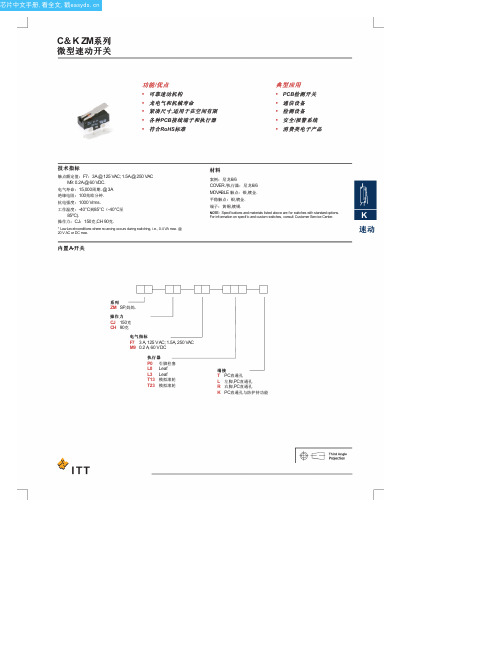
C&K ZM系列
微型速动开关
功 能 /优 点 • 可靠速动机构 • 龙电气和机械寿命 • 紧凑尺寸,适用于在空间有限 • 各种PCB接线端子和执行器 • 符合RoHS标准
典型应用 • PCB检测开关 • 通信设备 • 检测设备 • 安全/报警系统 • 消费类电子产品
芯片中文手册,看全文,戳
C&K ZM系列
微型速动开关
系列
ZM
ZM SUBMINIATURE SNAP-ACTING SWITCHES – SP MOMENTARY
.156 (4,2).2来自6 (6,50).016 (0,4)
PC MOUNTING
C NO
FREE POS.
OPER. POS. .276 ± .012
.071 (1,8 ±
.122 (3,1)
Third Angle Projection Dimensions are shown: Inch (mm) Specifications and dimensions subject to change
技术指标
触点额定值:F7:3A @ 125 VAC; 1.5A @ 250 VAC M9: 0.2A @ 60 VDC.
Protek 3201_3290N 中文说明书_东方嘉仪
误动作时
U
U
虽然此仪器的电源可以开机,如有误动作(不正常工作或死机现象)时,请按照下述步骤安 全使用。
1) Protek 3201N/3290N接上电源(电源适配器AC Adapter)。 2) 按Reset 键。 (Reset 键在 Battery 装入口的底面) 3) 不正常工作时, 另外有一种方法是 通过系统菜单(Menu)的测试(TEST)组上选择
PC电脑连接(Connection for PC)……………………………………………………………64
自动电源Auto Power……………………………………………………………………………65
偏置Offset……………………………………………………………………………………66
菜单(Menu)…………………………………………………………………………………67
电 话 :(青 岛 )0532-86069117 (南京)025-52405707 (天津)022-60501825
9
3201N/3290N 用户手册
仪器仪表销售 注册品牌
存储 /读出Save/Load ………………………………………………………………………54
频率计数器(Frequency Counter)………………………………………………………58
RESET 键即可。
电池 (Battery)
U
此仪器使用Ni-MH Rechargeable Battery(镍-氢充电电池;以下称Ni-MH充电电池) 6个,可 以充电后使用。
1) Ni-MH充电电池为消耗品,随着使用时间的增加,Ni-MH充电电池的寿命会缩短。 2) Ni-MH 充电电池的实际使用时间,缩短为刚刚购买时的实际使用时间一半时请更换
伊顿进口变速箱文档(46页)

Synchro -9 Twin Countershaft Fully Synchronized Transmission
? 2002 Eaton Corporation. A l l rights reserved.
S9 transmission training manaul
特点 Characteristics
S-9(synchro-9)系列9档双中间轴全同步器变速器是美国伊顿公司最新投放市场的高科技产品, 整体采用了美国 EATON 公司先进的设计理念,主副箱组合设计,主箱为手操纵,副箱为 气操纵,具有 9个前进档, 1个倒档。
1. 主、副箱全同步器设计,配置有当今世界最先进的自动增力式同步器
倒档 Power Flow Reverse Gear
CONFIDENTIAL
动力传递路线图 Power Flow
低速档 Power Flow LO Gear
CONFIDENTIAL
动力传递路线图 Power Flow
1档
Power Flow 1 stGear
CONFIDENTIAL
动力传递路线图 Power
主变速器为手操纵,低 1-2 -3-4 及倒档在低档区, 5 -6-7 -8档在高 档区。有两个空档位置,一个在低档区 3-4 档,另一个在高档区 5 -6档。副变速器为气 操纵换档气压为 0. 75Mpa 。
RTS 型双H 换档机构操纵手球位置图 双H 换档机构气动线路示意图
装在双H 操纵装置中横向换档杆上的拨头直接控制双 H 气阀,使其 接通高档区的气路或低档区的气路,来实现高档区档位与低档区档 位的自由转换。双 H 气阀上的孔口 1为进气口,孔口 2和4为出气口 ,孔口 3和5 为排气口。
AM29DL323DT120资料

For More Information
3OHDVH FRQWDFW \RXU ORFDO $0' RU )XMLWVX VDOHV RIILFH IRU DGGLWLRQDO LQIRUPDWLRQ DERXW 6SDQVLRQ PHPRU\ VROXWLRQV
Publication Number 21534 Revision D
Publication# 21534 Rev: D Amendment/+6 Issue Date: Website () for the latest information.
元器件交易网
GENERAL DESCRIPTION
The Am29DL322D/323D/324D family consists of 32 megabit, 3.0 volt-only flash memory devices, organized as 2,097,152 words of 16 bits each or 4,194,304 bytes of 8 bits each. Word mode data appears on DQ0–DQ15; byte mode data appears on DQ0–DQ7. The device is designed to be programmed in-system with the standard 3.0 volt VCC supply, and can also be programmed in standard EPROM programmers. The devices are available with an access time of 70, 90 or 120 ns. The devices are offered in 48-pin TSOP and 63-ball FBGA packages. Standard control pins—chip enable (CE#), write enable (WE#), and output enable (OE#)—control normal read and write operations, and avoid bus contention issues. The devices requires only a single 3.0 volt power supply for both read and write functions. Internally generated and regulated voltages are provided for the program and erase operations. Sector as bonus space, reading and writing like any other flash sector, or may permanently lock their own code there. DMS (Data Management Software) allows systems to easily take advantage of the advanced architecture of the simultaneous read/write product line by allowing removal of EEPROM devices. DMS will also allow the system software to be simplified, as it will perform all functions necessary to modify data in file structures, as opposed to single-byte modifications. To write or update a particular piece of data (a phone number or configuration data, for example), the user only needs to state which piece of data is to be updated, and where the updated data is located in the system. This is an advantage compared to systems where user-written software must keep track of the old data location, status, logical to physical translation of the data onto the Flash memory device (or memory devices), and more. Using DMS, user-written software does not need to interface with the Flash memory directly. Instead, the user's software accesses the Flash memory by calling one of only six functions. AMD provides this software to simplify system design and software integration efforts. The device offers complete compatibility with the JEDEC single-power-supply Flash command set standard . Commands are written to the command register using standard microprocessor write timings. Reading data out of the device is similar to reading from other Flash or EPROM devices. The host system can detect whether a program or erase operation is complete by using the device status bits: RY/BY# pin, DQ7 (Data# Polling) and DQ6/DQ2 (toggle bits). After a program or erase cycle has been completed, the device automatically returns to the read mode. The sector erase architecture allows memory sectors to be erased and reprogrammed without affecting the data contents of other sectors. The device is fully erased when shipped from the factory. Hardware data protection measures include a low VCC detector that automatically inhibits write operations during power transitions. The hardware sector protection feature disables both program and erase operations in any combination of the sectors of memory. This can be achieved in-system or via programming equipment. The device offers two power-saving features. When addresses have been stable for a specified amount of time, the device enters the automatic sleep mode. The system can also place the device into the standby mode . Power consumption is greatly reduced in both modes.
雅特力 AT32F415系列 数据手册说明书

基于ARM®32位的Cortex®-M4微控制器,带64 K字节至256 K字节闪存、sLib、USB OTG、11个定时器、1个ADC、2个比较器、12个通信接口功能⏹内核:ARM®32位的Cortex®-M4 CPU−最高150 MHz工作频率,带存储器保护单元(MPU),内建单周期乘法和硬件除法−具有DSP指令集⏹存储器−从64 K字节至256 K字节的闪存程序/数据存储器− 18 K字节的系统存储器可作启动加载程序(Bootloader)用外,也可一次性配置成一般用户程序和数据区− 32 K字节的SRAM− sLib:将指定之主存储区设为执行代码安全库区,此区代码仅能调用无法读取⏹时钟、复位和电源管理− 2.6至3.6伏供电和I/O引脚−上电/断电复位(POR/PDR)、可编程电压监测器(PVD)− 4至25 MHz晶体振荡器−内嵌经出厂调校的48 MHz RC振荡器(25 °C达1 %精度,-40 °C至+105 °C达2.5 %精度),带自动时钟校准功能(ACC)−内嵌带校准的40 kHz RC振荡器−带校准功能的32 kHz晶体振荡器⏹低功耗−睡眠、停机、和待机模式− V BAT为ERTC和20个32位的后备寄存器供电⏹1个12位A/D转换器,0.5 μs转换时间(多达16个输入通道)−转换范围:0至3.6 V−一组采样和保持功能−温度传感器⏹2个比较器⏹DMA:14通道DMA控制器−支持的外设:定时器、ADC、SDIO、I2S、SPI、I2C、和USART⏹调试模式−串行线调试(SWD)和JTAG接口⏹多达55个快速I/O端口− 27/39/55个多功能双向的I/O口,所有I/O口可以映像到16个外部中断;几乎所有I/O口可容忍5V输入信号−所有I/O口均为快速I/O,寄存器存取速度最高f AHB/2⏹多达11个定时器−多达5个16位定时器+2个32位定时器,每个定时器有多达4个用于输入捕获/输出比较/PWM或脉冲计数的通道和增量编码器输入− 1个16位带死区控制和紧急刹车,用于电机控制的PWM高级控制定时器− 2个看门狗定时器(独立的和窗口型的)−系统时间定时器:24位自减型计数器⏹ERTC:增强型RTC,具亚秒级精度及硬件日历⏹多达12个通信接口− 2个I2C接口(支持SMBus/PMBus)−多达5个USART接口(支持ISO7816,LIN,IrDA接口和调制解调控制)− 2个SPI接口(50M位/秒),2个均可复用为I2S接口− CAN接口(2.0B主动),内置256字节的专用SRAM− USB 2.0全速设备/主机/OTG控制器,内置1280字节的专用SRAM,设备模式时支持无晶振(Crystal-less)− SDIO接口⏹CRC计算单元⏹96位的芯片唯一代码⏹封装− LQFP64 10 x 10 mm− LQFP64 7 x 7 mm− LQFP48 7 x 7 mm− QFN48 6 x 6 mm− QFN32 4 x 4 mm目录1介绍 (9)2规格说明 (10)2.1器件一览 (11)2.2概述 (12)2.2.1ARM®Cortex®-M4,配有DSP指令 (12)2.2.2存储器保护单元(MPU) (14)2.2.3闪存存储器 (14)2.2.4循环冗余校验(CRC)计算单元 (14)2.2.5内置SRAM (14)2.2.6嵌套的向量式中断控制器(NVIC) (14)2.2.7外部中断/事件控制器(EXTI) (15)2.2.8时钟和启动 (15)2.2.9启动模式 (17)2.2.10供电方案 (17)2.2.11供电监控器 (17)2.2.12电压调压器 (17)2.2.13低功耗模式 (18)2.2.14直接存储器访问控制器(DMA) (18)2.2.15增强型实时时钟(ERTC)和后备份寄存器 (18)2.2.16定时器和看门狗 (19)2.2.17内部集成电路总线(I2C) (21)2.2.18通用同步/异步收发器(USART) (21)2.2.19串行外设接口(SPI) (21)2.2.20内部集成音频接口(I2S) (21)2.2.21安全数字输入/输出接口(SDIO) (21)2.2.22控制器区域网络(CAN) (21)2.2.23通用串行总线OTG全速(USB OTG FS) (22)2.2.24通用输入输出口(GPIO) (22)2.2.26模拟/数字转换器(ADC) (22)2.2.27温度传感器 (22)2.2.28比较器(COMP) (23)2.2.29串行线JTAG调试口(SWJ-DP) (23)3引脚定义 (24)4存储器映像 (30)5电气特性 (31)5.1测试条件 (31)5.1.1最小和最大数值 (31)5.1.2典型数值 (31)5.1.3典型曲线 (31)5.1.4负载电容 (31)5.1.5引脚输入电压 (31)5.1.6供电方案 (32)5.1.7电流消耗测量 (32)5.2绝对最大额定值 (33)5.3工作条件 (34)5.3.1通用工作条件 (34)5.3.2上电和掉电时的工作条件 (34)5.3.3内嵌复位和电源控制模块特性 (35)5.3.4内置的参照电压 (36)5.3.5供电电流特性 (36)5.3.6外部时钟源特性 (44)5.3.7内部时钟源特性 (48)5.3.8PLL特性 (50)5.3.9存储器特性 (50)5.3.10EMC特性 (51)5.3.11绝对最大值(电气敏感性) (52)5.3.13NRST引脚特性 (55)5.3.14TMR定时器特性 (55)5.3.15通信接口 (56)5.3.16CAN(控制器局域网络)接口 (64)5.3.1712位ADC特性 (64)5.3.18比较器特性 (68)5.3.19温度传感器特性 (69)6封装特性 (70)6.1LQFP64 – 10 x 10 mm封装数据 (70)6.2LQFP64 – 7 x 7 mm封装数据 (72)6.3LQFP48 – 7 x 7 mm封装数据 (74)6.4QFN48 – 6 x 6 mm封装数据 (76)6.5QFN32 – 4 x 4 mm封装数据 (78)6.6热特性 (80)7订货代码 (81)8版本历史 (82)表目录表1. 选型列表 (1)表2. AT32F415系列器件功能和配置 (11)表3. 启动加载程序(Bootloader)的管脚配置 (17)表4. 定时器功能比较 (19)表5. AT32F415系列引脚定义 (27)表6. 电压特性 (33)表7. 电流特性 (33)表8. 温度特性 (33)表9. 通用工作条件 (34)表10. 上电和掉电时的工作条件 (34)表11. 内嵌复位和电源控制模块特性 (35)表12. 内置的参照电压 (36)表13. 运行模式下的最大电流消耗 (37)表14. 睡眠模式下的最大电流消耗 (38)表15. 停机和待机模式下的典型和最大电流消耗 (38)表16. V BAT的典型和最大电流消耗(LSE和ERTC开启) (40)表17. 运行模式下的典型电流消耗 (41)表18. 睡眠模式下的典型电流消耗 (42)表19. 内置外设的电流消耗 (43)表20. 高速外部用户时钟特性 (44)表21. 低速外部用户时钟特性 (45)表22. HSE 4~25 MHz振荡器特性 (46)表23. LSE振荡器特性(f LSE = 32.768 kHz) (47)表24. HSI振荡器特性 (48)表25. LSI振荡器特性 (48)表26. 低功耗模式的唤醒时间 (49)表27. PLL特性 (50)表28. 闪存存储器特性 (50)表29. 闪存存储器寿命和数据保存期限 (50)表30. EMS特性 (51)表31. ESD绝对最大值 (52)表32. 电气敏感性 (52)表33. I/O静态特性 (53)表34. 输出电压特性 (54)表35. 输入交流特性 (54)表36. NRST引脚特性 (55)表37. TMRx特性 (55)表38. I2C接口特性 (56)表39. SCL频率(f PCLK1 = 36 MHz,V DD = 3.3 V) (57)表40. SPI特性 (58)表41. I2S特性 (60)表42. SD/MMC接口特性 (62)表43. USB OTG全速启动时间 (63)表44. USB OTG全速直流特性 (63)表45. USB OTG全速电气特性 (63)表46. ADC特性 (64)表47. f ADC = 14MHz时的最大R AIN (65)表48. f ADC = 28MHz时的最大R AIN (65)表49. ADC精度(V DDA = 3.0~3.6 V, T A = 25 °C) (66)表50. ADC精度(V DDA = 2.6~3.6 V, T A = -40~105 °C) (66)表51. 比较器特性 (68)表52. 温度传感器特性 (69)表53. LQFP64 – 10 x 10 mm 64脚薄型正方扁平封装机械数据 (71)表54. LQFP64 – 7 x 7 mm 64脚薄型正方扁平封装机械数据 (73)表55. LQFP48 – 7 x 7 mm 48脚薄型正方扁平封装机械数据 (75)表56. QFN48 – 6 x 6 mm 48脚正方扁平无引线封装机械数据 (77)表57. QFN32 – 4 x 4 mm 32脚正方扁平无引线封装机械数据 (79)表58. 封装的热特性 (80)表59. AT32F415系列订货代码信息图示 (81)表60. 文档版本历史 (82)图目录图1. AT32F415系列功能框图 (13)图2. 时钟树 (16)图3. AT32F415系列LQFP64引脚分布 (24)图4. AT32F415系列LQFP48引脚分布 (25)图5. AT32F413系列QFN48引脚分布 (25)图6. AT32F415系列QFN32引脚分布 (26)图7. 存储器图 (30)图8.引脚的负载条件 (31)图9. 引脚输入电压 (31)图10. 供电方案 (32)图11. 电流消耗测量方案 (32)图12. 上电复位和掉电复位波形图 (35)图13.调压器在运行模式时,停机模式下的典型电流消耗在不同的V DD时与温度的对比 (39)图14.调压器在低功耗模式时,停机模式下的典型电流消耗在不同的V DD时与温度的对比 (39)图15. 待机模式下的典型电流消耗在不同的V DD时与温度的对比 (40)图16. V BAT的典型电流消耗(LSE和ERTC开启)在不同的V BAT电压时与温度的对比 (40)图17. 外部高速时钟源的交流时序图 (44)图18. 外部低速时钟源的交流时序图 (45)图19. 使用8 MHz晶体的典型应用 (46)图20. 使用32.768 kHz晶体的典型应用 (47)图21. HSI振荡器精度与温度的对比 (48)图22. 建议的NRST引脚保护 (55)图23. I2C总线交流波形和测量电路 (57)图24. SPI时序图–从模式和CPHA = 0 (59)图25. SPI时序图–从模式和CPHA = 1 (59)图26. SPI时序图–主模式 (59)图27. I2S从模式时序图(Philips协议) (60)图28. I2S主模式时序图(Philips协议) (61)图29. SDIO高速模式 (62)图30. SD默认模式 (62)图31. USB OTG全速时序:数据信号上升和下降时间定义 (63)图32. ADC精度特性 (66)图33. 使用ADC典型的连接图 (67)图34. 供电电源和参考电源去藕线路 (67)图35. 比较器迟滞图 (68)图36. V SENSE对温度理想曲线图 (69)图37. LQFP64 – 10 x 10 mm 64脚薄型正方扁平封装图 (70)图38. LQFP64 – 10 x 10 mm标记(封装俯视图) (71)图39. LQFP64 – 7 x 7 mm 64脚薄型正方扁平封装图 (72)图40. LQFP64 – 7 x 7 mm标记(封装俯视图) (73)图41. LQFP48 – 7 x 7 mm 48脚薄型正方扁平封装图 (74)图42. LQFP48 – 7 x 7 mm标记(封装俯视图) (75)图43. QFN48 – 6 x 6 mm 48脚正方扁平无引线封装图 (76)图44. QFN48 – 6 x 6 mm标记(封装俯视图) (77)图45. QFN32 – 4 x 4 mm 32脚正方扁平无引线封装图 (78)图46. QFN32 – 4 x 4 mm标记(封装俯视图) (79)1 介绍本文给出了AT32F415系列产品的订购信息和器件的机械特性。
TEL T2000-00 T2000-A37 Selcall Kit 产品说明书

M2000-00T2000-A37 Selcall Kit8.17.1 8.17T2000-A37 Selcall KitThe T2000-A37 Selcall PCB plugs into an options connector on the top side of the logic PCB, and provides selective tone calling (Selcall) facilities for T2010, T2015 or T2020 Series II radios.This option allows selective individual or group calls within a fleet of radios, on chan-nels that have Selcall programmed. Selcall parameters and features are set up and ena-bled during radio programming. Both Sigtec and International group formats are supported by the T2000-A37 Selcall PCB.T2010 and T2015 radios require version 3 radio firmware when a T2000-A37 Selcall kit is fitted. If your radio uses an earlier firmware version, a version 3 microprocessor can be purchased as a separate item, with IPN 002-26870-62.The T2000-A37 does not support the EIA tone set.The following topics are covered in this Section:Section Title Page 8.17.1Components Required8.8.2 8.17.2Fitting8.8.2 8.17.3PCB Information8.8.48.17.2T2000-A37 Selcall Kit M2000-008.17.1Components RequiredThe T2000-A37 Selcall kit contains the following components:8.17.2Fitting1Refer to Figure 8.17.1.Remove the top cover of the radio by unscrewing the four cover screws, unscrew the logic PCB and fold-out.2T2010 & T2015 Radios (if a firmware version upgrade is required)Use a PLCC extractor to remove the existing microprocessor from SK505, located on the top side of T2010/T2015 logic PCB.Fit the new microprocessor and check that pin 1 is correctly aligned.Remove PCB link resistor #R714.Fit PCB link resistor #R715 (use a 0Ω resistor or a solder short).Note:O n logic PCB IPN 220-01377-00 or IPN 220-01377-01, “#R715” is designated “#R714A”.3Position the T2000-A37 PCB as shown, and plug into the connector on the T2000logic PCB, as follows:4Position the foam tape provided on top of X1 and X2 on the T2000-A37 SelcallPCB.5Carefully fold the logic PCB back in position and secure using the three logic PCB retaining screws.Refit the top cover.6Refer to the T2000 Programming Software User’s Manual (IPN 439-22000-02, orlater) for set-up information.QuantityDescription1T2000-A37 PCB assembly 12mm PVC foam tape ModelPCB IPN Connector Circuit Reference T2010 & T2015220-01377-0X P1T2020220-01344-0X #T3K44M2000-00T2000-A37 Selcall Kit8.17.3Figure 8.17.1 T2000-A37 Selcall PCB Mounting8.17.4T2000-A37 Selcall Kit M2000-00 8.17.3PCB InformationT2000-A37 Parts List (IPN 220-01600-01)Ref IPN Description Ref IPN Description&43470397:3033&$3#7:31#589#.053(&4334;048433033&$3#3936#&+,3#431#839#;:5.043(&4434;046553033&$3#3936#&+,3#5533#839#132.08(&4534;046553033&$3#3936#&+,3#5533#839#132.08(&4734;048433033&$3#3936#&+,3#431#839#;:5.043(&493470397:3033&$3#7:31#589#.053(&534;049433034&$3#3936##4331#.;3053(#<89#499&634;049433034&$3#3936##4331#.;3053(#<89#499&734;049433034&$3#3936##4331#.;3053(#<89#499&834;045553033&$3#3936#&+,3#553#839#132#.08(&934;045553033&$3#3936#&+,3#553#839#132#.08(&:34;049433034&$3#3936##4331#.;3053(#<89#499&;3470397:3033&$3#7:31#589#.053(,&4335054995033,&#;0%,7#3,&49&955#(3520,&533505333;05;,&#);;5;'8#'&6#6(/#35&655436;0447:30335(6#3936#&+,3#7(:#4249:#.08(54336;0485530335(6#3936#&+,3#55.#4249:#.08(54436;0485530335(6#3936#&+,3#55.#4249:#.08(54536;0485530335(6#3936#&+,3#55.#4249:#.08(54736;0485530335(6#3936#&+,3#55.#4249:#.08(5536;0447:30335(6#3936#&+,3#7(:#4249:#.08(5636;0485530335(6#3936#&+,3#55.#4249:#.08(5736;0494330335(6#3936#&+,3#433.#4249:#.08(5836;0487:30335(6#3936#&+,3#7:.#4249:#.08(5:36;0494330335(6#3936#&+,3#433.#4249:#.08(6457304333303<&211#60'#57:$<;45:70343:3033;7/#713330+=#+&7<826#8/$725553034933034/,3&%#75333#6(/&$//#;566:3$698033344087/$%(/#:+,7(#5:488925#<3-5700698033433053/$%(/#:+,7(#62$#5;;4400#4.67,.69<0353870337$3(#6$#7(6$#45-91700#480#52//6<<0333430;9%$*#67$7,+,(/',1*#45:;53600743034397034 3.*#+($'(5#&$5'#+1(:#/2*2,74;056:33033)771*#,16#753330$6:#6(/#.,7T2000-A37 Selcall PCB (IPN 220-01600-01) - Top SideT2000-A37 Selcall PCB (IPN 220-01600-01) - Bottom SideM2000-00T2000-A37 Selcall Kit 8.17.7Copyright TEL30/11/998.17.8T2000-A37 Selcall Kit M2000-00。
tektronix TBS2000 Series数字存储光框(DSG)商品介绍说明书

Digital Storage OscilloscopeTBS2000 Series DatasheetWith a 9-inch WVGA display, 20 million point record length and 1 GS/s sample rate, TBS2000 Series Oscilloscopes capture and displaysignificantly more signal to help you evaluate designs faster. Easily and confidently analyze your signals with new on-waveform cursor readouts and 32 automated measurements, each with informative tips to help you quickly choose the right one. The TekVPI ® probe interface works with traditional BNC connections, but also enables wide application coverage with the latest active voltage probes and current probes.Key performance specifications2 and 4 analog channel models100 and 70 MHz bandwidth modelsUp to 1 GS/s sampling rate20 M record length on all channels 5 year warrantyKey features9-inch WVGA color display15 horizontal grids show 50% more signalTekVPI probe interface supports active, differential, and current probeswith automatic scaling and units32 automated measurements, and FFT function for thorough waveformanalysisHelpEverywhere provides helpful on-screen tipsBuilt-in Scope Intro handbook provides operating instructions andoscilloscope fundamentals2-channel models are highly-portable at 2.62 kg (5.8 lbs)ConnectivityUSB 2.0 host port on the front panel for quick and easy data storageWi-Fi interface provides wireless communications capability 1supportUSB 2.0 device port on rear panel for easy connection to a PC LXI compliant 10/100BASE-T Ethernet port for remote control over LANEducationCourseware function presents lab exercise guidance on the display Fully compatible with TekSmartLab lab management software for educationDesigned to make your work easierThe TBS2000 Series is designed for easy operation and quick hands-on learning. Dedicated controls provide quick access to important settings, so you can evaluate signals faster. Many oscilloscopes provide 8 verticaldivisions and 10 horizontal divisions, but the TBS2000 gives you 10 vertical divisions and 15 horizontal divisions , so you can see more of your signal.The display also offers more room for measurement results and menu information.1A Wi-Fi adapter is available in some countries from Tektronix distributors as an accessory, model TEK-USB-WIFI. See Ordering Information for details.Designed for outstanding waveform visualization and analysisLong record length with pan and zoom – Record length is selectable,from 2000 samples up to 20 million samples for capturing long time periods. The exceptionally long record length will help you find signal anomalies and verify digital communications. To help navigate longacquisitions, the Zoom function lets you quickly pan through the record andzoom in to see signal details.In Zoom mode, the upper display gives an overview of up to 20 M points. The detailedzoomed view is shown in the lower display.The cursor readouts are presented on the waveform display. Cursors can be used to measure time, amplitude, or both.Versatile triggering and acquisition modes – The trigger system is designed for troubleshooting today's mixed signal designs. Beyond a basic edge trigger, it also includes pulse width and runt triggering, which are especially useful for troubleshooting digital sections of your designs. Pulse width triggering is perfect for hunting narrow glitches or timeout conditions.You specify a voltage threshold and a width, and the oscilloscope triggers when the pulses are too narrow, too wide, or of a particular duration. Runt triggering is designed to capture signals that are shorter in amplitude than expected. It lets you specify two voltage thresholds and a width. If a pulse amplitude falls between the two thresholds, the oscilloscope will trigger.DatasheetThe default acquisition mode is Sample Mode which works well for most applications. However the instrument also offers Peak Detect Mode which is useful for hunting spikes, and Average Mode which can help reduce noise on repetitive signals.Automated measurements are easier than ever – A comprehensive set of automated measurements enable fast and convenient testing for a widerange of signals and applications.Measurements are all listed and selected on a single screen.A single measurement selection screen makes it easy to choose from 32 automated measurements without having to hunt through multiple menus. Choose from among your most frequently-used measurements which are tracked at the top of the page, or select from four categories:frequency, time, amplitude, and area. The HelpEverywhere system provides tips for each measurement, making it easier to know whichmeasurement to use and to understand the results.Measurements are transparent so waveforms are not obscured.Measurements are color coded by the source, and are presented on a transparent background, so waveforms are not obscured by the readouts.FFT function – You can understand the frequency content of your signals with the FFT function by pressing the dedicated front-panel FFT button.Display only the FFT, or turn on the source waveform display to see both the spectrum and the time domain waveform. A transparent readout showsimportant settings without blocking the FFT display.The time domain source waveform can be displayed above the FFT frequency spectrum.Built-in tips for faster setupHelpEverywhere is a unique feature on theTBS2000. It shows instant help information as you navigate through key menus. The tips includemeasurement information, application tips, and general guidance in the form of text and graphics. You can turn tips on and off from theHelpEverywhere menu.HelpEverywhere tips explain important settings.TBS2000 Series Digital Storage OscilloscopeOn-screen scope fundamentalsScope Intro is a brief handbook embedded in the TBS2000. Pressing the front panel Function button gives you access to information on oscilloscope basic operations, as well as an overview of the TBS2000 and TekSmartLabLab Management System for education.Scope Intro covers basic oscilloscope and TBS2000 usageFirst in its class with wireless communicationsOn the rear of the instrument, you will find several communications ports.The USB device port or LAN port can be used to control the instrumentusing the fully-documented command set.Wi-Fi adapters are configured through integrated setup menus and support seamless wireless communicationsThe TBS2000 is the first oscilloscope in its class to support wireless communication. Plug a Wi-Fi dongle into the USB host port and set the interface for Wi-Fi from the front panel. A Wi-Fi dongle is available as TEK-USB-WIFI. Several off-the-shelf dongles have also been tested and their operation confirmed.LXI embedded Web page for instrument control – LXI is an industry standard based on LAN connectivity for flexible, reliable, and efficient communication and control. TBS2000 supports LXI Core 2011. TheTBS2000 LXI Web page can be accessed by simply typing the instrumentIP address into any Web browser.LXI control screen and waveform display enable remote control over EthernetDatasheetTekVPI ® Interface and active probe supportThe TekVPI probe interface sets the standard for ease of use in probing.With this interface the TBS2000 Series supports a wide range of the latest voltage and current probes, providing coverage for many applications.These probes are powered by and communicate with the TBS2000 through the interface. Scale factors and status information, such as error conditions,are sent to the instrument for processing and display. This saves you from having to manually set scale factors, calculate offsets, or monitor for openjaw conditions or the need to degauss your current probes.TekVPI probes communicate scale settings, ranges, and status to the TBS2000.Innovative new education solutionsThe TBS2000 offers distinctive new ways to enable educators to devote more time to teaching circuit concepts instead of lab setup andmanagement.The Courseware function allows students to see lab information on the instrument display.The integrated Courseware function allows professors to load lab exercises on the instrument to give students guidance at each station, and provides a structured framework into which students can capture data to incorporate into their reports. Over 100 sample lab exercises are available for download from the Tektronix Courseware Resource Center.The TBS2000 can be easily integrated into the TekSmartLab System.Together they enable educators to preset a lab full of instruments with a few mouse-clicks, and allow lab instructors to track every student's progress from one central workstation.Performance you can count onTektronix has industry-leading service and support, and every TBS2000series oscilloscope is backed with a standard 5-year warranty.TBS2000 Series Digital Storage OscilloscopeDatasheetSpecificationsAll specifications are guaranteed unless noted otherwise. All specifications apply to all models unless noted otherwise.Model overviewVertical system analog channelsHardware bandwidth limits20 MHzInput coupling DC, AC, or GNDInput impedance 1 MΩ ± 2 %, 11.5 pF ± 2.5 pFInput sensitivity range 2 mV/Div to 5 V/DivVertical resolution8 bitsMaximum input voltage, 1 MΩ300 V RMS with peaks ≤ ±450 VAcquisition modesSample Acquire sampled values.Peak Detect Captures glitches as narrow as 3.5 ns at all sweep speeds.Average From 2 to 512 waveforms included in average.Hi-Res Averages multiple sample of one acquisition interval into one waveform point.Roll Scrolls waveforms right to left across the screen at sweep speeds slower than or equal to 40 ms/div (400 ms/div at 20M recordlength).Math modesAll units:Ch 1 - Ch 2Ch 2 - Ch 1Ch 1 + Ch 2Ch 1 X Ch 2FFT4 channel units:Ch 3 - Ch 4Ch 3 + Ch 4Ch 4 - Ch 3Ch 3 X Ch 4DC balance± (1 mV +0.1 div)DC gain accuracy± 3% 10 mV/div through 5 V/div-± 4% typical 2 mV/div and 5 mV/divDC voltage measurement accuracy average modeAverage of 16 waveforms ±((DC Gain Accuracy) X |reading - (offset - position)| + Offset Accuracy + 0.11 div + 1 mV)Delta Volts between any two averages of ≥16 waveforms acquired with the same oscilloscope setup and ambient conditions ±(DC Gain Accuracy X |reading| + 0.08 div + 1.4 mV)Vertical position range ± 5 divisions Vertical offset rangesAnalog bandwidth, DC coupled100 MHz models:DC to ≥100 MHz for 2 mV/div through 5 V/div.70 MHz models:DC to ≥70 MHz for 2 mV/div through 5 V/div.Common mode rejection ratio (CMRR), typical100:1 at 60 Hz, reducing to 10:1 with 50 MHz sine wave with equal Volts/div and coupling settings on each channel.Channel-to-channel isolationHorizontal system analog channelsMaximum duration of timecaptured at highest sample rate (all channels)40 msTime base range2 ns/div to 100 sec/div Time-base delay time range -15 divisions to 5000 s Deskew range ±100 nsTime base accuracy±25 ppm over any ≥1 ms intervalTrigger systemTrigger modes Auto, Normal, and Single Trigger holdoff range 20 ns to 8 sTrigger typesEdge Positive or negative slope on any channel. Coupling includes DC, HF reject, LF reject, and noise reject.Pulse width Trigger on width of positive or negative pulses that are >, <, =, or ≠ a specified period of time.RuntTrigger on a pulse that crosses one threshold but fails to cross a second threshold before crossing the first again.Trigger coupling analog channelsDC, Noise Reject, High Freq Reject, Low Freq Reject.TBS2000 Series Digital Storage OscilloscopeVertical system analog channelsSensitivity, edge–type trigger, DC coupledTrigger level rangesInput channels: ± 4.90 divisions from center screenData storageNonvolatile memory retention time, typical No time limit for Front Panel Settings, saved waveforms, setups, and calibration constants.Real-Time clockA programmable clock providing time in years, months, days, hours, minutes, and seconds.Waveform measurementsCursorsTime, amplitude and screen.Automated measurements32, of which up to six can be displayed on-screen at any one time. Measurements include: Period, Frequency, Rise Time, Fall Time, Positive Duty Cycle, Negative Duty Cycle, Positive Pulse Width, Negative Pulse Width, Burst Width, Phase, PositiveOvershoot, Negative Overshoot, Peak to Peak, Amplitude, High, Low, Max, Min, Mean, Cycle Mean, RMS, Cycle RMS, Positive Pulse Count, Negative Pulse Count, Rising Edge Count, Falling Edge Count, Area, Cycle Area, Delay FR, Delay FF, Delay FR,and Delay RR.GatingIsolate the specific occurrence within an acquisition to take measurements on, using either the screen, between waveform cursors or full record length.Waveform mathArithmetic Add, subtract, and multiply waveforms.FFTSpectral magnitude. Set FFT Vertical Scale to Linear RMS or dBV RMS, and FFT Window to Rectangular, Hamming, Hanning, or Blackman-Harris.Remote control softwareLXI web pageLXI Core 2011. Built-in web page enables remote control of horizontal and vertical scale, trigger settings, and measurements.Allows waveform and image save to USB flash drive.Display systemDisplay type 9 inch (228 mm) wide format liquid crystal TFT color display.Display resolution 800 horizontal by 480 vertical displayed pixels (WVGA).Waveform styles Vectors, Variable Persistence, and Infinite Persistence.Graticules Grid, None.FormatYT and XY.DatasheetTrigger systemTBS2000 Series Digital Storage Oscilloscope Input output portsUSB 2.0 high-speed host port Supports USB mass storage devices, Wi-Fi dongle, One port available on rear panel and one on front panel.USB 2.0 high-speed device portDevice port Rear-panel connector allows for communication/control of oscilloscope through USBTMC or GPIB with a TEK-USB-488.Compatible USB-WIFI dongles TBS2xxx USBWIFI optionTEK-USB-WIFI accessoryTP-LINK TL-WN823N, NETGEAR WNA1000M, WNA3100MLAN port (Ethernet)RJ-45 connector, supports 10/100BASE-T.Probe compensatorAmplitude 5 VFrequency 1 kHzKensington-style lock Rear-panel security slot connects to standard Kensington-style lock.Power sourcePower source voltage100 to 240 V AC RMS ±10%Power source frequency45 Hz to 65 Hz (90 to 264 V)360 Hz to 440 Hz (100 to 132 V)Power consumption80 W maximumPhysical characteristicsDimensionsTBS2xx2:Height: 174.9 mm (6.89 in)Width: 372.4 mm (14.66 in)Depth: 103.3 mm (4.07 in)TBS2xx4:Height: 201.5mm (7.93 in)Width: 412.8 mm (16.25 in)Depth: 128.1 mm (5.04 in)WeightTBS2xx2: 2.62 kg (5.8 lbs.), standalone instrument.5.1 kg (11.2 lbs.), when packaged for domestic shipment.TBS2xx4: 4.17 kg (9.2 lbs.), stand-alone instrument.7 kg (15.4 lbs.), when packaged for domestic shipment.Cooling clearance50 mm (2 in) required on left side and rear of instrument.DatasheetEMC, environment, and safetyTemperatureOperating:0 °C to +50 °C (+32 ºF to 122 ºF)Nonoperating:-40 °C to +71 °C (-40 ºF to 160 ºF)HumidityOperating:High: +30 °C to +50 °C, 5% to 60% relative humidityLow: 0 °C to +30 °C, 5% to 95% relative humidityNonoperating:High: +30 °C to +55 °C, 5% to 60% relative humidityLow: 0 °C to +30 °C 5% to 95% relative humidityAltitudeOperating:Up to 3,000 meters (9,842 feet).Non-Operating:Up to 12,000 meters (39,370 feet).RegulatoryElectromagnetic compatibility EC Council Directive 2004/108/ECSafety UL61010-1:2004; CAN/CSA-C22.2 No. 61010.1: 2004; EN61010-1:2001; complies with the Low Voltage Directive 2004/108/EC forProduct Safety.TBS2000 Series Digital Storage Oscilloscope Ordering informationModelsTBS207270 MHz, 1 GS/s, 20 M record length, 2-channel digital storage oscilloscopeTBS2102100 MHz, 1 GS/s, 20 M record length, 2-channel digital storage oscilloscopeTBS207470 MHz, 1 GS/s, 20 M record length, 4-channel digital storage oscilloscopeTBS2104100 MHz, 1 GS/s, 20 M record length, 4-channel digital storage oscilloscopeStandard accessoriesProbes TPP0100100 MHz, 10x passive probe (one per analog channel)Accessories063-4568-xx Documentation CD071-3445-xx Installation and safety manual077-1149-xx Programmer manual, available on documentation CD and on Tek Web-Power cord-Calibration certificate documenting traceability to National Metrology Institute(s) andISO9001 quality system registrationWarranty Five-year warranty covering all parts and labor, excluding probes.Recommended accessoriesProbes Tektronix offers over 100 different probes to meet your application needs. For a comprehensive listing of available probes, pleasevisit /probes.P5100A 2.5 kV, 500 MHz, 100X high-voltage passive probeTDP0500500 MHz TekVPI ® differential voltage probe with ±42 V differential input voltageTHDP0200±1.5 kV 200 MHz high-voltage differential probeTHDP0100±6 kV 100 MHz high-voltage differential probeTAP1500 1.5 GHz TekVPI ® active voltage probeTCP002050 MHz TekVPI ® 20 Ampere AC/DC current probeTCP0030A120 MHz TekVPI ® 30 Ampere AC/DC current probeTCP015020 MHz TekVPI ® 150 Ampere AC/DC current probeTCP202050 MHz BNC 20 Ampere AC/DC current probeP5202A100 MHz, 640 V High Voltage differential probeP5205A100 MHz, 1.3 kV High Voltage differential probeP5210A50 MHz, 5.6 kV High Voltage differential probeAccessoriesTPA-BNC TekVPI ® to TekProbe ® BNC adapterACD2000Soft transit case, for TBS2072 and TBS2102ACD4000B Soft transit case, for TBS2074 and TBS2104TEK-DPG TekVPI ® Deskew pulse generator signal source067-1686-XX Power measurement deskew and calibration fixtureTEK-USB-WIFI USB Wi-Fi 2 dongle for TBS2000 series onlyTEK-USB-488GPIB-to-USB adapterDatasheetInstrument optionsTBS2XXX USBWIFI 2USB Wi-Fi dongle for TBS2000 series onlyTBS2XXX P2221Replaces standard probes with P2221 probes (200 MHz passive voltage probes with 1x/10x attenuation)Power plugOpt. A0North America power plug (115 V, 60 Hz)Opt. A1Universal Euro power plug (220 V, 50 Hz)Opt. A2United Kingdom power plug (240 V, 50 Hz)Opt. A3Australia power plug (240 V, 50 Hz)Opt. A4North America power plug (240 V, 50 Hz)Opt. A5Switzerland power plug (220 V, 50 Hz)Opt. A6Japan power plug (100 V, 50/60 Hz)Opt. A10China power plug (50 Hz)Opt. A11India power plug (50 Hz)Opt. A12Brazil power plug (60 Hz)Opt. A99No power cordLanguage optionsOpt. L0English front panel overlayOpt. L1French front panel overlayOpt. L2Italian front panel overlayOpt. L3German front panel overlayOpt. L4Spanish front panel overlayOpt. L5Japanese front panel overlayOpt. L6Portuguese front panel overlayOpt. L7Simplified Chinese front panel overlayOpt. L8Traditional Chinese front panel overlayOpt. L9Korean front panel overlayOpt. L10Russian front panel overlayOpt. L99No manualLanguage options include translated front-panel overlay only, manuals with different language are available on Tek web.Service optionsOpt. D1Calibration Data Report2Certified to comply with CE, FCC and IC regulations. Available in Australia, Canada, China, EU Region, New Zealand, and United States. For other compatible Wi-Fi adapters, see Compatible USB-WIFI dongles under Input output ports specifications.Tektronix is registered to ISO 9001 and ISO 14001 by SRI Quality System Registrar.Product(s) complies with IEEE Standard 488.1-1987, RS-232-C, and with Tektronix Standard Codes and Formats.Product Area Assessed: The planning, design/development and manufacture of electronic Test and Measurement instruments.TBS2000 Series Digital Storage OscilloscopeDatasheetASEAN / Australasia (65) 6356 3900 Austria 00800 2255 4835*Balkans, Israel, South Africa and other ISE Countries +41 52 675 3777 Belgium 00800 2255 4835*Brazil +55 (11) 3759 7627 Canada180****9200Central East Europe and the Baltics +41 52 675 3777 Central Europe & Greece +41 52 675 3777 Denmark +45 80 88 1401Finland +41 52 675 3777 France 00800 2255 4835*Germany 00800 2255 4835*Hong Kong 400 820 5835 India 000 800 650 1835 Italy 00800 2255 4835*Japan 81 (3) 6714 3086 Luxembourg +41 52 675 3777 Mexico, Central/South America & Caribbean 52 (55) 56 04 50 90Middle East, Asia, and North Africa +41 52 675 3777 The Netherlands 00800 2255 4835*Norway 800 16098People's Republic of China 400 820 5835 Poland +41 52 675 3777 Portugal 80 08 12370Republic of Korea +822 6917 5084, 822 6917 5080 Russia & CIS +7 (495) 6647564 South Africa +41 52 675 3777Spain 00800 2255 4835*Sweden 00800 2255 4835*Switzerland 00800 2255 4835*Taiwan 886 (2) 2656 6688 United Kingdom & Ireland 00800 2255 4835*USA180****9200* European toll-free number. If not accessible, call: +41 52 675 3777For Further Information. Tektronix maintains a comprehensive, constantly expanding collection of application notes, technical briefs and other resources to help engineers working on the cutting edge of technology. Please visit . Copyright © Tektronix, Inc. All rights reserved. Tektronix products are covered by U.S. and foreign patents, issued and pending. Information in this publication supersedes that in all previously published material. Specification andprice change privileges reserved. TEKTRONIX and TEK are registered trademarks of Tektronix, Inc. All other trade names referenced are the service marks, trademarks, or registered trademarks of their respective companies.05 Sep 2017 3GW-60235-3 。
- 1、下载文档前请自行甄别文档内容的完整性,平台不提供额外的编辑、内容补充、找答案等附加服务。
- 2、"仅部分预览"的文档,不可在线预览部分如存在完整性等问题,可反馈申请退款(可完整预览的文档不适用该条件!)。
- 3、如文档侵犯您的权益,请联系客服反馈,我们会尽快为您处理(人工客服工作时间:9:00-18:30)。
A3290 and A3291Selection GuidePart Number Packing 1Package TypeMagnetic Switchpoints *Operate, B OP (G)Release, B RP(G)A3290KLHLT-T 3000 pieces per 7-in. reel Surface mount SOT23W 5 to 50–50 to –5A3290KUA-T 500 pieces per bulk bag Through hole ultramini SIP A3291KLHLT-T 3000 pieces per 7-in. reel Surface mount SOT23W 10 to 100–100 to –10A3291KUA-T500 pieces per bulk bagThrough hole ultramini SIP*Algebraic convention used: (+) south polarity, (–) north polarity.Pin-out DiagramsTerminal ListNameNumberFunctionLH UA VCC 11Power supply OUT 23Output GND32GroundPackage LHPackage UAAbsolute Maximum RatingsCharacteristicSymbol NotesRating Units Supply VoltageV CC 26.5V Reverse Battery Voltage V RCC –30V Output Off Voltage V OUT 26V Continuous Output Current I OUT Device provides internal current limiting to helpprotect itself from output short circuits25mA Reverse Output Current I ROUT –50mA Magnetic Flux DensityB Unlimited G Operating Ambient Temperature T A Range K–40 to 125ºC Maximum Junction Temperature T J (max)165ºC Storage TemperatureT stg–65 to 170ºCELECTRICAL CHARACTERISTICS over operating temperature range, unless otherwise notedCharacteristic Symbol Test ConditionsMin.Typ.1Max Units Supply Voltage Range 2V CC Operating, T J < 165°C 4.2–24V Output Leakage Current I OFF V OUT = 24 V, B < B RP ––10μA Output Saturation Voltage V OUT(SAT)I OUT = 20 mA, B > B OP –185500mV Output Current Limit 3I ON B > B OP 30–60mA Power-On Time t PO V CC > 4.2 V ––50μs Chopping Frequency f C–800–kHz Output Rise Time t RR LOAD = 820 Ω, C LOAD = 20 pF –0.2 2.0μs Output Fall Time t F R LOAD = 820 Ω, C LOAD = 20 pF–0.1 2.0μs Supply Current I CCB < B RP , V CC = 12 V– 3.08.0mA B > B OP , V CC = 12 V– 4.08.0mA Reverse Battery Current I RCC V RCC = –30 V –––5.0mA Zener Voltage V Z + V D I CC = 15 mA, T A = 25°C 283237V Zener Impedance Z Z + Z D I CC = 15 mA, T A = 25°C–50–Ω!Typical data at T A= 25°C, 12 V2Maximum V CCmust be derated for power dissipation and junction temperature. See application information.3Non-R device option only.MAGNETIC CHARACTERISTICS 1 over V CC range, unless otherwise notedCharacteristicSymbolTest Conditions Min.Max.Units Operate Point 2B OPA3290T A = 25°C and T A(max)550G T A = –40°C550G A3291T A = 25°C and T A(max)10100G T A = –40°C10100G Release Point 3B RPA3290T A = 25°C and T A(max)–50–5G T A = –40°C–50–5G A3291T A = 25°C and T A(max)–100–10G T A = –40°C–100–10G Hysteresis (B OP – B RP ) B HYSA3290T A = 25°C and T A(max)10100G T A = –40°C–100G A3291T A = 25°C and T A(max)20200G T A = –40°C–200G1The positive polarity symbol (+) indicates south magnetic field, and the negative polarity symbol (–) indicates north magnetic field.2Required polarity observed and transition of magnetic gradient through B OP . See functional description.3Required polarity observed and transition of magnetic gradient through BRP after B OP . See functional description.THERMAL CHARACTERISTICS may require derating at maximum conditions, see application informationCharacteristicSymbolTest Conditions*Value Units Package Thermal ResistanceR θJAPackage LH, 1-layer PCB with copper limited to solder pads 228ºC/W Package LH, 2-layer PCB with 0.463 in.2 of copper area each side connected by thermal vias110ºC/W Package UA, 1-layer PCB with copper limited to solder pads165ºC/W*Additional thermal information available on Allegro website.6789234510111213141516171819202122232425Temperature (ºC)M a x i m u m A l l o w a b l e V C C (V )Power Derating CurveV CC(min)V CC(max)100200300400500600700800900100011001200130014001500160017001800190020406080100120140160180Temperature (°C)P o w e r D i s s i p a t i o n ,P D (m W )Power Dissipation versus Ambient TemperatureFunctional DescriptionFigure 2. Chopper stabilization circuit (dynamic quadrature offset cancellation)Chopper-Stabilized TechniqueThe Hall element can be considered as a resistor array similar to a Wheatstone bridge. A basic circuit is shown in figure 1, demonstrating the effect of the magnetic field flux density, B, impinging on the Hall element. When using Hall effect tech-nology, a limiting factor for switchpoint accuracy is the small signal voltage, V HALL , developed across the Hall element. This voltage is disproportionally small relative to the offset that can be produced at the output of the Hall device, caused by device overmolding, temperature dependencies, and thermal stress.A large portion of the offset is a result of the mismatching of these resistors. The A3290 and A3291 use a proprietary dynamic offset cancellation technique, with an internal high-frequency clock, to reduce the ressidual offset. The chopper-stabilizingtechnique cancels the mismatching of the resistor circuit by changing the direction of the current flowing through the Hall element. To do so, CMOS switches and Hall voltage measure-ment taps are used, while maintaining V HALL signal that is induced by the external magnetic flux.The signal is then captured by a sample-and-hold circuit and fur-ther processed using low-offset bipolar circuitry. This technique produces devices that have an extremely stable quiescent Hall output voltage, are immune to thermal stress, and have precise recoverability after temperature cycling. This technique will also slightly degrade the device output repeatability. A relatively high sampling frequency is used in order to process faster signals.More detailed descriptions of the circuit operation can be found on the Allegro Web site, including: Technical Paper STP 97-10, Monolithic Magnetic Hall Sensor Using Dynamic Quadrature Offset Cancellation , and Technical Paper STP 99-1, Chopper-Stabilized Amplifiers with a Track-and-Hold Signal Demodula-tor .OperationThe outputs of the A3290 and A3291 switch low (turn on) when a magnetic field perpendicular to the Hall sensor transitions through and exceeds the Operate Point threshold, B OP . This is illustrated in figure 3. After turn-on, the output is capable of sinking 25 mA, and the output voltage reaches V OUT(SAT).HYSV OUT(off)V O U TV OUT(on)(sat)Hysteresis of ΔV OUT Switching Due to ΔBFigure 3. Output voltage responds to sensed magnetic flux density.Figure 1. Hall element, basic circuit operationApplication InformationNote that these devices latch; that is, after a south (+) polarity magnetic field of sufficient strength impinging on the branded face of the device turns on the device, the device remains on until the magnetic field is reduced below the Release Point threshold, B RP . At that transition, the device output goes high (turns off). The difference in the magnetic operate and release points is the hysteresis, B HYS , of the device. This built-in hysteresis allowsclean switching of the output, even in the presence of external mechanical vibration and electrical noise.When the devices are powered on, if the ambient magnetic field has an intensity that is between B OP and B RP , the initial output state is indeterminate. The first time that the level of B either rises through B OP , or falls through B RP , however, the correct output state is obatined.It is strongly recommended that an external bypass capacitor be connected (in close proximity to the Hall sensor) between the supply and ground of the device to reduce both external noise and noise generated by the chopper-stabilization technique. This configuration is shown in figure 4.The simplest form of magnet that will operate these devices is a ring magnet.Other methods of operation, such as linear magnets, are possible.The device must be operated below the maximum junctiontemperature of the device, T J(max). Under certain combinations of peak conditions, reliable operation may require derating supplied power or improving the heat dissipation properties of the applica-tion. The Package Thermal Resistance, R θJA , is a figure of merit summarizing the ability of the application and the device to dissi-pate heat from the junction (die), through all paths to the ambient air. Its primary component is the Effective Thermal Conductivity, K, of the printed circuit board, including adjacent devices and traces. Radiation from the die through the device case, R θJC , is relatively small component of R θJA . Ambient air temperature, T A , and air motion are significant external factors, damped by overmolding. Sample power dissipation results are given in the Thermal Characteristics section. Additional thermal data is also available on the Allegro website.Extensive applications information for Hall-effect sensors isavailable in: Hall-Effect IC Applications Guide , Application Note 27701 and Guidelines for Designing Subassemblies Using Hall-Effect Devices , Application Note 27703.1Figure 4. Typical basic application circuit. A bypass capacitor is highly recommended.Package LH, 3-Pin SOT23WPackage UA, 3-Pin SIPCopyright ©2005-2008, Allegro MicroSystems, Inc.The products described herein are manufactured under one or more of the following U.S. patents: 5,045,920; 5,264,783; 5,442,283; 5,389,889; 5,581,179; 5,517,112; 5,619,137; 5,621,319; 5,650,719; 5,686,894; 5,694,038; 5,729,130; 5,917,320; and other patents pending.Allegro MicroSystems, Inc. reserves the right to make, from time to time, such de p ar t ures from the detail spec i f i c a t ions as may be required to per-mit improvements in the per f or m ance, reliability, or manufacturability of its products. Before placing an order, the user is cautioned to verify that the information being relied upon is current.Allegro’s products are not to be used in life support devices or systems, if a failure of an Allegro product can reasonably be expected to cause the failure of that life support device or system, or to affect the safety or effectiveness of that device or system.The in f or m a t ion in c lud e d herein is believed to be ac c u r ate and reliable. How e v e r, Allegro MicroSystems, Inc. assumes no re s pon s i b il i t y for its use; nor for any in f ringe m ent of patents or other rights of third parties which may result from its use.For the latest version of this document, visit our website:Hall element, not to scaleCExact case and lead configuration at supplier discretion within limits shown。