NE67483B中文资料
Keysight N6783A-MFG移动通信DC电源模块数据手册说明书

N6783A-MFGData SheetIntroductionDesigned speciically to test battery-powered(mobile) devices in manufacturing–Up to 4 outputs in 1U of rack space–Modern connectivity – USB, LXI-C certiied LAN, and GPIB–Fast output voltage transient response to ensure uninterrupted tests–Built-in digitizing measurement system for fast, accurate measurementsDesigned for manufacturing, automated test environmentsThe Keysight Technologies, Inc. N6783A-MFG mobile communications DC power module offers advanced features speciically for testing battery-powered (mobile) devices in manufacturing or automated test environments. TheN6783A-MFG has excellent voltage transient response which ensures a stable output voltage is maintained atthe device under test (DUT) during load transients. This maximizes system throughput by eliminating inadvertent device shutdowns that occur if the voltage is allowed to droop too low, such as when a non-specialized powersupply is used. The built-in digitizer also allows for maximum throughput by providing fast, accurate, lexiblemeasurements that are customizable to the level of speed and accuracy desired.Key features–Up to 4 outputs in 1U of rack space when used in the N6700B low-proile modular power system mainframe–Modern connectivity – USB, LXI-C certiied LAN, and GPIB (resides in mainframe, not module)–Fast output voltage transient response to ensure uninterrupted tests–High-speed digitized measurements increase system throughput by performing fast measurements upto every 20 μs with the built-in 50 kHz digitizer–Two current measurement ranges for accurate measurement of transmit as well as stand-by currents–Current sinking for testing and calibrating charger circuitry–Protection features, such as overvoltage and over-current protection (OVP and OCP)–Part of the lexible N6700 modular power system family which enables you to customize your test systemto your speciic needs with over 20 DC power modules to choose fromPart of the N6700 modular power system familyThe new N6783A-MFG is a part of the N6700 modular power system family, which consists of the N6700low-proile mainframes for automated test environments and the N6705 DC power analyzer mainframe forR&D. The product family has four mainframes and over 25 DC power modules, providing a complete spectrumof solutions, from R&D through design validation and manufacturing. For more information please visit:/ind/n6700Advanced mobile device test: battery drain analysis, battery emulationThe N6783A-MFG was designed for manufacturing test only. For advanced battery drain analysis and/orbattery emulation in R&D use the N6781A 2-quadrant source/measure unit for battery drain analysis.For additional details visit /ind/n6781Performance Speciications and CharacteristicsThis is an abbreviated list of the specification and characteristics. For the full list of specifications and characteristics, please see the N6700 Module Power System Specifications Guide, literature number N6700-90001.N6783A-MFG speciicationsTime3< 45 µs1. Output current is derated 1% per °C above 40 °C.2. Applies when measuring the default value of 1024 data points.3. When relay Option 761 is installed, the settling band is ± 90 mV. The time is < 75 µs.Supplemental Characteristics N6783A-MFG characteristicsPeak-to-peak 6 mASupplemental Characteristics (continued)Continuous current(applies above 0.50 V output)2 AN6783A-MFG CharacteristicsOrdering informationWeb resourcesModel number: N6783A-MFGDescription: Mobile Communications DC Power ModuleRelated literatureVisit our web sites for additional product information and literature. N6783A-MFG Mobile Communications DC Power Module /find/n6783a-mfgN6700B Low-Profile Modular Power System Mainframe /find/n6705N6781A 2-Quadrant Source/Measure Unit for Battery Drain Analysis /find/n6781– Keysight N6700 MPS Low-Profile Modular Power System Product Overview , literature number 5989-1411EN – N6700 Modular Power System Specifications Guide , literature number N6700-90001myKeysight/find/mykeysightA personalized view into the information most relevant to you.AdvancedTCA® Extensions for Instrumentation and Test (AXIe) is anopen standard that extends the AdvancedTCA for general purpose and semiconductor test. Keysight is a founding member of the AXIe consortium. ATCA®, AdvancedTCA®, and the ATCA logo are registered US trademarks of the PCI Industrial Computer Manufacturers Group.LAN eXtensions for Instruments puts the power of Ethernet and theWeb inside your test systems. Keysight is a founding member of the LXI consortium.PCI eXtensions for Instrumentation (PXI) modular instrumentation delivers arugged, PC-based high-performance measurement and automation system.Three-Year Warranty/find/ThreeYearWarrantyKeysight’s commitment to superior product quality and lower total costof ownership. The only test and measurement company with three-yearwarranty standard on all instruments, worldwide.Keysight Assurance Plans/find/AssurancePlansUp to five years of protection and no budgetary surprises to ensure yourinstruments are operating to specification so you can rely on accuratemeasurements./qualityKeysight Technologies, Inc.DEKRA Certified ISO 9001:2008Quality Management SystemKeysight Channel Partners/find/channelpartnersGet the best of both worlds: Keysight’s measurement expertise and productbreadth, combined with channel partner convenience./find/n6783a-mfg/find/n6705/find/n6781For more information on KeysightTechnologies’ products, applications orservices, please contact your local Keysightoffice. The complete list is available at:/find/contactusAmericasCanada(877) 894 4414Brazil55 11 3351 7010Mexico001 800 254 2440United States(800) 829 4444Asia PaciicAustralia 1 800 629 485China800 810 0189Hong Kong800 938 693India 1 800 112 929Japan0120 (421) 345Korea080 769 0800Malaysia 1 800 888 848Singapore180****8100Taiwan0800 047 866Other AP Countries(65) 6375 8100Europe & Middle EastAustria0800 001122Belgium0800 58580Finland0800 523252France0805 980333Germany***********Ireland1800 832700Israel 1 809 343051Italy800 599100Luxembourg+32 800 58580Netherlands0800 0233200Russia8800 5009286Spain0800 000154Sweden0200 882255Switzerland0800 805353Opt. 1 (DE)Opt. 2 (FR)Opt. 3 (IT)United Kingdom0800 0260637For other unlisted countries:/find/contactus(BP-07-10-14)06 | Keysight | N6783A-MFG Mobile Communications DC Power Module for the N6700 Modular Power System - Data SheetThis information is subject to change without notice.© Keysight Technologies, 2011-2014Published in USA, August 1, 20145990-8643ENN6783A-MFG。
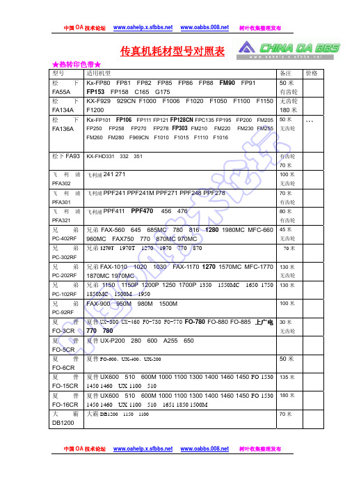
传真机耗材型号对照
国 三星 SF-5800 SF-5800P
佳能 L770
SF-5805P
SF-5905P
硒鼓
5000 页
硒鼓
硒鼓
硒鼓
2500 页
硒鼓
2500 页
硒鼓
中 佳能 FX-2 佳能 L500
佳能 FX-3 佳能 L250
L600 L380
L350
L200
L240
L280
硒鼓 硒鼓
佳能 FX-4 佳能 L900 L880
硒鼓
理光 1465 理光 FAX SL310
硒鼓
理光 EM-1 理光 FAX EL800
硒鼓
中国 OA 技术论坛 树叶收集整理发布
中国 OA 技术论坛 树叶收集整理发布
UG-3221 松下 UG-3220 松下 UG-3313 松下 KX-PEP5 三星 SF5100D3 三星 SF5800D5 佳能 FX-1
松下 UF490 590
术
松下 UF-A8710 8880 8770 1100
技 松下 KX-6500 6100 6300 A 三星 SF5100、SF5100P、Msys-5100P、SF-530 SF535e SF-531P、SF-515 O SF550 SF808
兄弟 1270T 1970T 1270 1970 770 870
技 兄弟 FAX-1010 1020 1030 FAX-1170 1270 1570MC MFC-1770
1870MC 1970MC
A 兄弟 1150 1150P 1200P 1250 1700P 1350 1550MC 1650 1750 O 1850MC 1500M 1950
国
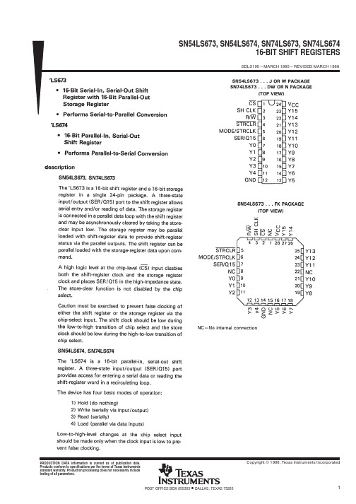
SN74LS674DWG4中文资料
Copyright © 1988, Texas Instruments Incorporated PRODUCTION DATA information is current as of publication date.Products conform to specifications per the terms of Texas Instrumentsstandard warranty. Production processing does not necessarily includetesting of all parameters.POST OFFICE BOX 655303 • DALLAS, TEXAS 752652POST OFFICE BOX 655303 • DALLAS, TEXAS 752653 POST OFFICE BOX 655303 • DALLAS, TEXAS 752654POST OFFICE BOX 655303 • DALLAS, TEXAS 752655 POST OFFICE BOX 655303 • DALLAS, TEXAS 752656POST OFFICE BOX 655303 • DALLAS, TEXAS 75265IMPORTANT NOTICETexas Instruments Incorporated and its subsidiaries(TI)reserve the right to make corrections,modifications,enhancements, improvements,and other changes to its products and services at any time and to discontinue any product or service without notice. Customers should obtain the latest relevant information before placing orders and should verify that such information is current and complete.All products are sold subject to TI’s terms and conditions of sale supplied at the time of order acknowledgment.TI warrants performance of its hardware products to the specifications applicable at the time of sale in accordance with TI’s standard warranty.Testing and other quality control techniques are used to the extent TI deems necessary to support this warranty.Except where mandated by government requirements,testing of all parameters of each product is not necessarily performed.TI assumes no liability for applications assistance or customer product design.Customers are responsible for their products and applications using TI components.To minimize the risks associated with customer products and applications,customers should provide adequate design and operating safeguards.TI does not warrant or represent that any license,either express or implied,is granted under any TI patent right,copyright,mask work right,or other TI intellectual property right relating to any combination,machine,or process in which TI products or services are rmation published by TI regarding third-party products or services does not constitute a license from TI to use such products or services or a warranty or endorsement e of such information may require a license from a third party under the patents or other intellectual property of the third party,or a license from TI under the patents or other intellectual property of TI. Reproduction of information in TI data books or data sheets is permissible only if reproduction is without alteration and is accompanied by all associated warranties,conditions,limitations,and notices.Reproduction of this information with alteration is an unfair and deceptive business practice.TI is not responsible or liable for such altered documentation.Resale of TI products or services with statements different from or beyond the parameters stated by TI for that product or service voids all express and any implied warranties for the associated TI product or service and is an unfair and deceptive business practice.TI is not responsible or liable for any such statements.TI products are not authorized for use in safety-critical applications(such as life support)where a failure of the TI product would reasonably be expected to cause severe personal injury or death,unless officers of the parties have executed an agreement specifically governing such use.Buyers represent that they have all necessary expertise in the safety and regulatory ramifications of their applications,and acknowledge and agree that they are solely responsible for all legal,regulatory and safety-related requirements concerning their products and any use of TI products in such safety-critical applications,notwithstanding any applications-related information or support that may be provided by TI.Further,Buyers must fully indemnify TI and its representatives against any damages arising out of the use of TI products in such safety-critical applications.TI products are neither designed nor intended for use in military/aerospace applications or environments unless the TI products are specifically designated by TI as military-grade or"enhanced plastic."Only products designated by TI as military-grade meet military specifications.Buyers acknowledge and agree that any such use of TI products which TI has not designated as military-grade is solely at the Buyer's risk,and that they are solely responsible for compliance with all legal and regulatory requirements in connection with such use.TI products are neither designed nor intended for use in automotive applications or environments unless the specific TI products are designated by TI as compliant with ISO/TS16949requirements.Buyers acknowledge and agree that,if they use anynon-designated products in automotive applications,TI will not be responsible for any failure to meet such requirements. Following are URLs where you can obtain information on other Texas Instruments products and application solutions:Products ApplicationsAmplifiers Audio /audioData Converters Automotive /automotiveDSP Broadband /broadbandInterface Digital Control /digitalcontrolLogic Military /militaryPower Mgmt Optical Networking /opticalnetworkMicrocontrollers Security /securityLow Power /lpw Telephony /telephonyWirelessVideo&Imaging /videoWireless /wirelessMailing Address:Texas Instruments,Post Office Box655303,Dallas,Texas75265Copyright©2007,Texas Instruments IncorporatedIMPORTANT NOTICETexas Instruments Incorporated and its subsidiaries(TI)reserve the right to make corrections,modifications,enhancements, improvements,and other changes to its products and services at any time and to discontinue any product or service without notice. Customers should obtain the latest relevant information before placing orders and should verify that such information is current and complete.All products are sold subject to TI’s terms and conditions of sale supplied at the time of order acknowledgment.TI warrants performance of its hardware products to the specifications applicable at the time of sale in accordance with TI’s standard warranty.Testing and other quality control techniques are used to the extent TI deems necessary to support this warranty.Except where mandated by government requirements,testing of all parameters of each product is not necessarily performed.TI assumes no liability for applications assistance or customer product design.Customers are responsible for their products and applications using TI components.To minimize the risks associated with customer products and applications,customers should provide adequate design and operating safeguards.TI does not warrant or represent that any license,either express or implied,is granted under any TI patent right,copyright,mask work right,or other TI intellectual property right relating to any combination,machine,or process in which TI products or services are rmation published by TI regarding third-party products or services does not constitute a license from TI to use such products or services or a warranty or endorsement e of such information may require a license from a third party under the patents or other intellectual property of the third party,or a license from TI under the patents or other intellectual property of TI. Reproduction of information in TI data books or data sheets is permissible only if reproduction is without alteration and is accompanied by all associated warranties,conditions,limitations,and notices.Reproduction of this information with alteration is an unfair and deceptive business practice.TI is not responsible or liable for such altered documentation.Resale of TI products or services with statements different from or beyond the parameters stated by TI for that product or service voids all express and any implied warranties for the associated TI product or service and is an unfair and deceptive business practice.TI is not responsible or liable for any such statements.TI products are not authorized for use in safety-critical applications(such as life support)where a failure of the TI product would reasonably be expected to cause severe personal injury or death,unless officers of the parties have executed an agreement specifically governing such use.Buyers represent that they have all necessary expertise in the safety and regulatory ramifications of their applications,and acknowledge and agree that they are solely responsible for all legal,regulatory and safety-related requirements concerning their products and any use of TI products in such safety-critical applications,notwithstanding any applications-related information or support that may be provided by TI.Further,Buyers must fully indemnify TI and its representatives against any damages arising out of the use of TI products in such safety-critical applications.TI products are neither designed nor intended for use in military/aerospace applications or environments unless the TI products are specifically designated by TI as military-grade or"enhanced plastic."Only products designated by TI as military-grade meet military specifications.Buyers acknowledge and agree that any such use of TI products which TI has not designated as military-grade is solely at the Buyer's risk,and that they are solely responsible for compliance with all legal and regulatory requirements in connection with such use.TI products are neither designed nor intended for use in automotive applications or environments unless the specific TI products are designated by TI as compliant with ISO/TS16949requirements.Buyers acknowledge and agree that,if they use anynon-designated products in automotive applications,TI will not be responsible for any failure to meet such requirements. Following are URLs where you can obtain information on other Texas Instruments products and application solutions:Products ApplicationsAmplifiers Audio /audioData Converters Automotive /automotiveDSP Broadband /broadbandInterface Digital Control /digitalcontrolLogic Military /militaryPower Mgmt Optical Networking /opticalnetworkMicrocontrollers Security /securityLow Power /lpw Telephony /telephonyWirelessVideo&Imaging /videoWireless /wirelessMailing Address:Texas Instruments,Post Office Box655303,Dallas,Texas75265Copyright©2007,Texas Instruments IncorporatedIMPORTANT NOTICETexas Instruments Incorporated and its subsidiaries(TI)reserve the right to make corrections,modifications,enhancements, improvements,and other changes to its products and services at any time and to discontinue any product or service without notice. Customers should obtain the latest relevant information before placing orders and should verify that such information is current and complete.All products are sold subject to TI’s terms and conditions of sale supplied at the time of order acknowledgment.TI warrants performance of its hardware products to the specifications applicable at the time of sale in accordance with TI’s standard warranty.Testing and other quality control techniques are used to the extent TI deems necessary to support this warranty.Except where mandated by government requirements,testing of all parameters of each product is not necessarily performed.TI assumes no liability for applications assistance or customer product design.Customers are responsible for their products and applications using TI components.To minimize the risks associated with customer products and applications,customers should provide adequate design and operating safeguards.TI does not warrant or represent that any license,either express or implied,is granted under any TI patent right,copyright,mask work right,or other TI intellectual property right relating to any combination,machine,or process in which TI products or services are rmation published by TI regarding third-party products or services does not constitute a license from TI to use such products or services or a warranty or endorsement e of such information may require a license from a third party under the patents or other intellectual property of the third party,or a license from TI under the patents or other intellectual property of TI. Reproduction of information in TI data books or data sheets is permissible only if reproduction is without alteration and is accompanied by all associated warranties,conditions,limitations,and notices.Reproduction of this information with alteration is an unfair and deceptive business practice.TI is not responsible or liable for such altered documentation.Resale of TI products or services with statements different from or beyond the parameters stated by TI for that product or service voids all express and any implied warranties for the associated TI product or service and is an unfair and deceptive business practice.TI is not responsible or liable for any such statements.TI products are not authorized for use in safety-critical applications(such as life support)where a failure of the TI product would reasonably be expected to cause severe personal injury or death,unless officers of the parties have executed an agreement specifically governing such use.Buyers represent that they have all necessary expertise in the safety and regulatory ramifications of their applications,and acknowledge and agree that they are solely responsible for all legal,regulatory and safety-related requirements concerning their products and any use of TI products in such safety-critical applications,notwithstanding any applications-related information or support that may be provided by TI.Further,Buyers must fully indemnify TI and its representatives against any damages arising out of the use of TI products in such safety-critical applications.TI products are neither designed nor intended for use in military/aerospace applications or environments unless the TI products are specifically designated by TI as military-grade or"enhanced plastic."Only products designated by TI as military-grade meet military specifications.Buyers acknowledge and agree that any such use of TI products which TI has not designated as military-grade is solely at the Buyer's risk,and that they are solely responsible for compliance with all legal and regulatory requirements in connection with such use.TI products are neither designed nor intended for use in automotive applications or environments unless the specific TI products are designated by TI as compliant with ISO/TS16949requirements.Buyers acknowledge and agree that,if they use anynon-designated products in automotive applications,TI will not be responsible for any failure to meet such requirements. Following are URLs where you can obtain information on other Texas Instruments products and application solutions:Products ApplicationsAmplifiers Audio /audioData Converters Automotive /automotiveDSP Broadband /broadbandInterface Digital Control /digitalcontrolLogic Military /militaryPower Mgmt Optical Networking /opticalnetworkMicrocontrollers Security /securityLow Power /lpw Telephony /telephonyWirelessVideo&Imaging /videoWireless /wirelessMailing Address:Texas Instruments,Post Office Box655303,Dallas,Texas75265Copyright©2007,Texas Instruments IncorporatedIMPORTANT NOTICETexas Instruments Incorporated and its subsidiaries(TI)reserve the right to make corrections,modifications,enhancements, improvements,and other changes to its products and services at any time and to discontinue any product or service without notice. Customers should obtain the latest relevant information before placing orders and should verify that such information is current and complete.All products are sold subject to TI’s terms and conditions of sale supplied at the time of order acknowledgment.TI warrants performance of its hardware products to the specifications applicable at the time of sale in accordance with TI’s standard warranty.Testing and other quality control techniques are used to the extent TI deems necessary to support this warranty.Except where mandated by government requirements,testing of all parameters of each product is not necessarily performed.TI assumes no liability for applications assistance or customer product design.Customers are responsible for their products and applications using TI components.To minimize the risks associated with customer products and applications,customers should provide adequate design and operating safeguards.TI does not warrant or represent that any license,either express or implied,is granted under any TI patent right,copyright,mask work right,or other TI intellectual property right relating to any combination,machine,or process in which TI products or services are rmation published by TI regarding third-party products or services does not constitute a license from TI to use such products or services or a warranty or endorsement e of such information may require a license from a third party under the patents or other intellectual property of the third party,or a license from TI under the patents or other intellectual property of TI. Reproduction of information in TI data books or data sheets is permissible only if reproduction is without alteration and is accompanied by all associated warranties,conditions,limitations,and notices.Reproduction of this information with alteration is an unfair and deceptive business practice.TI is not responsible or liable for such altered documentation.Resale of TI products or services with statements different from or beyond the parameters stated by TI for that product or service voids all express and any implied warranties for the associated TI product or service and is an unfair and deceptive business practice.TI is not responsible or liable for any such statements.TI products are not authorized for use in safety-critical applications(such as life support)where a failure of the TI product would reasonably be expected to cause severe personal injury or death,unless officers of the parties have executed an agreement specifically governing such use.Buyers represent that they have all necessary expertise in the safety and regulatory ramifications of their applications,and acknowledge and agree that they are solely responsible for all legal,regulatory and safety-related requirements concerning their products and any use of TI products in such safety-critical applications,notwithstanding any applications-related information or support that may be provided by TI.Further,Buyers must fully indemnify TI and its representatives against any damages arising out of the use of TI products in such safety-critical applications.TI products are neither designed nor intended for use in military/aerospace applications or environments unless the TI products are specifically designated by TI as military-grade or"enhanced plastic."Only products designated by TI as military-grade meet military specifications.Buyers acknowledge and agree that any such use of TI products which TI has not designated as military-grade is solely at the Buyer's risk,and that they are solely responsible for compliance with all legal and regulatory requirements in connection with such use.TI products are neither designed nor intended for use in automotive applications or environments unless the specific TI products are designated by TI as compliant with ISO/TS16949requirements.Buyers acknowledge and agree that,if they use anynon-designated products in automotive applications,TI will not be responsible for any failure to meet such requirements. Following are URLs where you can obtain information on other Texas Instruments products and application solutions:Products ApplicationsAmplifiers Audio /audioData Converters Automotive /automotiveDSP Broadband /broadbandInterface Digital Control /digitalcontrolLogic Military /militaryPower Mgmt Optical Networking /opticalnetworkMicrocontrollers Security /securityLow Power /lpw Telephony /telephonyWirelessVideo&Imaging /videoWireless /wirelessMailing Address:Texas Instruments,Post Office Box655303,Dallas,Texas75265Copyright©2007,Texas Instruments IncorporatedIMPORTANT NOTICETexas Instruments Incorporated and its subsidiaries(TI)reserve the right to make corrections,modifications,enhancements, improvements,and other changes to its products and services at any time and to discontinue any product or service without notice. Customers should obtain the latest relevant information before placing orders and should verify that such information is current and complete.All products are sold subject to TI’s terms and conditions of sale supplied at the time of order acknowledgment.TI warrants performance of its hardware products to the specifications applicable at the time of sale in accordance with TI’s standard warranty.Testing and other quality control techniques are used to the extent TI deems necessary to support this warranty.Except where mandated by government requirements,testing of all parameters of each product is not necessarily performed.TI assumes no liability for applications assistance or customer product design.Customers are responsible for their products and applications using TI components.To minimize the risks associated with customer products and applications,customers should provide adequate design and operating safeguards.TI does not warrant or represent that any license,either express or implied,is granted under any TI patent right,copyright,mask work right,or other TI intellectual property right relating to any combination,machine,or process in which TI products or services are rmation published by TI regarding third-party products or services does not constitute a license from TI to use such products or services or a warranty or endorsement e of such information may require a license from a third party under the patents or other intellectual property of the third party,or a license from TI under the patents or other intellectual property of TI. Reproduction of information in TI data books or data sheets is permissible only if reproduction is without alteration and is accompanied by all associated warranties,conditions,limitations,and notices.Reproduction of this information with alteration is an unfair and deceptive business practice.TI is not responsible or liable for such altered documentation.Resale of TI products or services with statements different from or beyond the parameters stated by TI for that product or service voids all express and any implied warranties for the associated TI product or service and is an unfair and deceptive business practice.TI is not responsible or liable for any such statements.TI products are not authorized for use in safety-critical applications(such as life support)where a failure of the TI product would reasonably be expected to cause severe personal injury or death,unless officers of the parties have executed an agreement specifically governing such use.Buyers represent that they have all necessary expertise in the safety and regulatory ramifications of their applications,and acknowledge and agree that they are solely responsible for all legal,regulatory and safety-related requirements concerning their products and any use of TI products in such safety-critical applications,notwithstanding any applications-related information or support that may be provided by TI.Further,Buyers must fully indemnify TI and its representatives against any damages arising out of the use of TI products in such safety-critical applications.TI products are neither designed nor intended for use in military/aerospace applications or environments unless the TI products are specifically designated by TI as military-grade or"enhanced plastic."Only products designated by TI as military-grade meet military specifications.Buyers acknowledge and agree that any such use of TI products which TI has not designated as military-grade is solely at the Buyer's risk,and that they are solely responsible for compliance with all legal and regulatory requirements in connection with such use.TI products are neither designed nor intended for use in automotive applications or environments unless the specific TI products are designated by TI as compliant with ISO/TS16949requirements.Buyers acknowledge and agree that,if they use anynon-designated products in automotive applications,TI will not be responsible for any failure to meet such requirements. Following are URLs where you can obtain information on other Texas Instruments products and application solutions:Products ApplicationsAmplifiers Audio /audioData Converters Automotive /automotiveDSP Broadband /broadbandInterface Digital Control /digitalcontrolLogic Military /militaryPower Mgmt Optical Networking /opticalnetworkMicrocontrollers Security /securityLow Power /lpw Telephony /telephonyWirelessVideo&Imaging /videoWireless /wirelessMailing Address:Texas Instruments,Post Office Box655303,Dallas,Texas75265Copyright©2007,Texas Instruments IncorporatedIMPORTANT NOTICETexas Instruments Incorporated and its subsidiaries(TI)reserve the right to make corrections,modifications,enhancements, improvements,and other changes to its products and services at any time and to discontinue any product or service without notice. Customers should obtain the latest relevant information before placing orders and should verify that such information is current and complete.All products are sold subject to TI’s terms and conditions of sale supplied at the time of order acknowledgment.TI warrants performance of its hardware products to the specifications applicable at the time of sale in accordance with TI’s standard warranty.Testing and other quality control techniques are used to the extent TI deems necessary to support this warranty.Except where mandated by government requirements,testing of all parameters of each product is not necessarily performed.TI assumes no liability for applications assistance or customer product design.Customers are responsible for their products and applications using TI components.To minimize the risks associated with customer products and applications,customers should provide adequate design and operating safeguards.TI does not warrant or represent that any license,either express or implied,is granted under any TI patent right,copyright,mask work right,or other TI intellectual property right relating to any combination,machine,or process in which TI products or services are rmation published by TI regarding third-party products or services does not constitute a license from TI to use such products or services or a warranty or endorsement e of such information may require a license from a third party under the patents or other intellectual property of the third party,or a license from TI under the patents or other intellectual property of TI. Reproduction of information in TI data books or data sheets is permissible only if reproduction is without alteration and is accompanied by all associated warranties,conditions,limitations,and notices.Reproduction of this information with alteration is an unfair and deceptive business practice.TI is not responsible or liable for such altered documentation.Resale of TI products or services with statements different from or beyond the parameters stated by TI for that product or service voids all express and any implied warranties for the associated TI product or service and is an unfair and deceptive business practice.TI is not responsible or liable for any such statements.TI products are not authorized for use in safety-critical applications(such as life support)where a failure of the TI product would reasonably be expected to cause severe personal injury or death,unless officers of the parties have executed an agreement specifically governing such use.Buyers represent that they have all necessary expertise in the safety and regulatory ramifications of their applications,and acknowledge and agree that they are solely responsible for all legal,regulatory and safety-related requirements concerning their products and any use of TI products in such safety-critical applications,notwithstanding any applications-related information or support that may be provided by TI.Further,Buyers must fully indemnify TI and its representatives against any damages arising out of the use of TI products in such safety-critical applications.TI products are neither designed nor intended for use in military/aerospace applications or environments unless the TI products are specifically designated by TI as military-grade or"enhanced plastic."Only products designated by TI as military-grade meet military specifications.Buyers acknowledge and agree that any such use of TI products which TI has not designated as military-grade is solely at the Buyer's risk,and that they are solely responsible for compliance with all legal and regulatory requirements in connection with such use.TI products are neither designed nor intended for use in automotive applications or environments unless the specific TI products are designated by TI as compliant with ISO/TS16949requirements.Buyers acknowledge and agree that,if they use anynon-designated products in automotive applications,TI will not be responsible for any failure to meet such requirements. Following are URLs where you can obtain information on other Texas Instruments products and application solutions:Products ApplicationsAmplifiers Audio /audioData Converters Automotive /automotiveDSP Broadband /broadbandInterface Digital Control /digitalcontrolLogic Military /militaryPower Mgmt Optical Networking /opticalnetworkMicrocontrollers Security /securityLow Power /lpw Telephony /telephonyWirelessVideo&Imaging /videoWireless /wirelessMailing Address:Texas Instruments,Post Office Box655303,Dallas,Texas75265Copyright©2007,Texas Instruments Incorporated。
常用测试碟型号一览表, testing disc

种类 细分 分类 品牌 型号 TCD-781 TCD-782 ABEX 信号测试碟 TCD-783 TCD-784 TCD-785 TCD-786 PHILIPS SONY SBC-444 YEDS-18 710 711 712 713 ABEX 普通CD 偏心系列 714 711R 712R 713R 714R PHILIPS 缺陷碟 划伤碟 黑点碟 ABEX ABEX ABEX PHILIPS 面振碟 ABEX PHILIPS MP3 ABEX 721R 721 726 725A 725B 444A 731RA 732RA VDD 4419 4278 3588 信号碟 ABEX R082W R091W R011W/R CD-R 偏心系列 缺陷 黑点 面振 信号 高反射 低反射 CD-RW 偏心系列 ABEX ABEX ABEX ABEX ABEX ABEX R012W/R R013W/R R021W/R R025W/R R032W/R W082W W082H W082L W011W W012W
面振量1。0
面振量1.0 普通版本 三洋版本 偏心量50 偏心量100 偏心量150
面振量0.4 面振量0.6 面振量1.0 0.8 偏心量50 偏心量100 偏心量150
面振量0.4 面振量0.6 面振量1.0 偏心量50 偏心量 偏碟型号一览表
特性简介 收录了99曲的标准光盘 标准光盘 8厘米标准光盘 标准光盘 以EIAJ CP-2403为标准的标准光盘 杜比定向逻辑测试光盘
偏心量0um误差0~15um 偏心量70um误差正负15um 偏心量140un误差正负15um 偏心量210um误差正负15um 偏心量280um误差正负15um 偏心量70um误差正负5um 偏心量140um误差正负5um 偏心量210um误差正负5um 偏心量280um误差正负5um 偏心150 偏心200 最大宽度3.0mm最小宽度0.4mm,每个阶梯增加0.2mm 最大宽度2.0mm最小宽度0.4mm,每个阶梯增加0.2mm 划伤碟 早期版本 现在版本 光盘转动时,在光盘直径93mm处的面振量是1.0mm 光盘转动时,在光盘直径116mm处的面振量是1.0mm
BB184中文资料
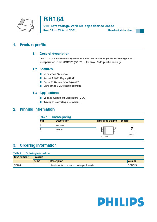
1.Product profile1.1General descriptionThe BB184 is a variable capacitance diode, fabricated in planar technology, and encapsulated in the SOD523 (SC-79) ultra small SMD plastic package.1.2Featuress Very steep CV curves C d(1V): 14 pF; C d(10V): 2 pF s C d(1V) to C d(10V) ratio: typical 7sUltra small SMD plastic package.1.3Applicationss Voltage Controlled Oscillators (VCO)s Tuning in low voltage television.2.Pinning information3.Ordering informationBB184UHF low voltage variable capacitance diodeRev. 02 — 22 April 2004Product data sheetTable 1:Discrete pinningPin Description Simplified outline Symbol1cathode 2anode12Top viewsym008Table 2:Ordering informationType numberPackage NameDescriptionVersion BB184-plastic surface mounted package; 2 leadsSOD5234.Marking5.Limiting values6.CharacteristicsTable 3:MarkingType numberMarking code BB184A2Table 4:Limiting valuesIn accordance with the Absolute Maximum Rating System (IEC 60134).Symbol ParameterConditionsMin Max Unit V R continuous reverse voltage -13V I F continuous forward current -10mA T stg storage temperature−55+150°C T joperating junction temperature−55+125°CTable 5:Electrical characteristics T j = 25°C unless otherwise specified.Symbol Parameter ConditionsMin Typ Max Unit I R reverse currentV R = 10 V; see Figure 2--10nA V R = 10 V; T j = 85°C; see Figure 2--200nA r s diode series resistance f = 470 MHz; C d =9pF -0.65-ΩC ddiode capacitancef = 1 MHz; see Figure 1 and 3V R = 1 V 12.71415.3pF V R = 4 V - 5.5-pF V R = 10 V1.8722.13pFcapacitance ratiof = 1 MHz67-capacitance matchingV R = 1 to 10 V; in a sequence of 5diodes (gliding)--2%C d 1V ()C d 10V ()------------------∆C d C d----------f = 1 MHz; T j = 25°C.Fig 1.Diode capacitance as a function of reverse voltage; typical values.Fig 2.Reverse current as a function of junctiontemperature; maximum values.Fig 3.Temperature coefficient of diode capacitanceas a function of reverse voltage; typical values.001aaa643101552025C d (pF)0V R (V)10−1102101001aaa65710210103I R (nA)1T j (°C)010080406020V R (V)10−1102101001aaa65810−310−410−2TC d (K -1)10−57.Package outlineFig 4.Package outline.REFERENCESOUTLINE VERSION EUROPEAN PROJECTIONISSUE DATE IECJEDECJEITA SOD523SC-7998-11-2502-12-13Plastic surface mounted package; 2 leadsSOD52300.5 1 mmscaleD 12H EEb pAcv M AAUNITb pc D E v mm A H E DIMENSIONS (mm are the original dimensions)Note1. The marking bar indicates the cathode.(1)0.340.260.170.110.10.850.751.251.150.650.581.651.558.Revision historyTable 6:Revision historyDocument ID Release date Data sheet status Change notice Order number SupersedesBB184_220040422Product data-9397 750 13004BB184_N_1 Modifications:•The format of this data sheet has been redesigned to comply with the new presentation andinformation standard of Philips SemiconductorsBB184_N_120040114Preliminary data-9397 750 12694-9.Data sheet status[1]Please consult the most recently issued data sheet before initiating or completing a design.[2]The product status of the device(s) described in this data sheet may have changed since this data sheet was published. The latest information is available on the Internet at URL .[3]For data sheets describing multiple type numbers, the highest-level product status determines the data sheet status.10.DefinitionsShort-form specification —The data in a short-form specification is extracted from a full data sheet with the same type number and title. For detailed information see the relevant data sheet or data handbook.Limiting values definition — Limiting values given are in accordance with the Absolute Maximum Rating System (IEC 60134). Stress above one or more of the limiting values may cause permanent damage to the device.These are stress ratings only and operation of the device at these or at any other conditions above those given in the Characteristics sections of the specification is not implied. Exposure to limiting values for extended periods may affect device reliability.Application information — Applications that are described herein for any of these products are for illustrative purposes only. Philips Semiconductors make no representation or warranty that such applications will be suitable for the specified use without further testing or modification.11.DisclaimersLife support —These products are not designed for use in life support appliances, devices, or systems where malfunction of these products can reasonably be expected to result in personal injury. Philips Semiconductors customers using or selling these products for use in such applications do so at their own risk and agree to fully indemnify Philips Semiconductors for any damages resulting from such application.Right to make changes —Philips Semiconductors reserves the right to make changes in the products - including circuits, standard cells, and/or software - described or contained herein in order to improve design and/or performance. When the product is in full production (status ‘Production’),relevant changes will be communicated via a Customer Product/Process Change Notification (CPCN). Philips Semiconductors assumes noresponsibility or liability for the use of any of these products, conveys no license or title under any patent, copyright, or mask work right to theseproducts,and makes no representations or warranties that these products are free from patent,copyright,or mask work right infringement,unless otherwise specified.12.Contact informationFor additional information, please visit: For sales office addresses, send an email to: sales.addresses@Level Data sheet status [1]Product status [2][3]DefinitionI Objective data Development This data sheet contains data from the objective specification for product development. Philips Semiconductors reserves the right to change the specification in any manner without notice.IIPreliminary dataQualificationThis data sheet contains data from the preliminary specification.Supplementary data will be published at a later date.Philips Semiconductors reserves the right to change the specification without notice,in order to improve the design and supply the best possible product.III Product data ProductionThis data sheet contains data from the product specification. Philips Semiconductors reserves the right to make changes at any time in order to improve the design,manufacturing and supply.Relevant changes will be communicated via a Customer Product/Process Change Notification (CPCN).13.Contents1Product profile. . . . . . . . . . . . . . . . . . . . . . . . . . 11.1General description. . . . . . . . . . . . . . . . . . . . . . 11.2Features . . . . . . . . . . . . . . . . . . . . . . . . . . . . . . 11.3Applications . . . . . . . . . . . . . . . . . . . . . . . . . . . 12Pinning information. . . . . . . . . . . . . . . . . . . . . . 13Ordering information. . . . . . . . . . . . . . . . . . . . . 14Marking. . . . . . . . . . . . . . . . . . . . . . . . . . . . . . . . 25Limiting values. . . . . . . . . . . . . . . . . . . . . . . . . . 26Characteristics. . . . . . . . . . . . . . . . . . . . . . . . . . 27Package outline . . . . . . . . . . . . . . . . . . . . . . . . . 48Revision history. . . . . . . . . . . . . . . . . . . . . . . . . 59Data sheet status. . . . . . . . . . . . . . . . . . . . . . . . 610Definitions . . . . . . . . . . . . . . . . . . . . . . . . . . . . . 611Disclaimers. . . . . . . . . . . . . . . . . . . . . . . . . . . . . 612Contact information . . . . . . . . . . . . . . . . . . . . . 6© Koninklijke Philips Electronics N.V.2004All rights are reserved.Reproduction in whole or in part is prohibited without the priorwritten consent of the copyright owner.The information presented in this document doesnot form part of any quotation or contract,is believed to be accurate and reliable and maybe changed without notice.No liability will be accepted by the publisher for anyconsequence of its use.Publication thereof does not convey nor imply any license underpatent- or other industrial or intellectual property rights.Date of release: 22 April 2004Document order number: 9397 750 13004。
1SMA5918BT3G中文资料

1SMA5913BT3 Series1.5 Watt PlasticSurface MountZener Voltage RegulatorsThis complete new line of 1.5 Watt Zener Diodes offers the following advantages.Features•Standard Zener Breakdown V oltage Range − 3.3 V to 68 V •ESD Rating of Class 3 (>16 kV) per Human Body Model •Flat Handling Surface for Accurate Placement •Package Design for Top Slide or Bottom Circuit Board Mounting •Low Profile Package•Ideal Replacement for MELF Packages•Pb−Free Packages are AvailableMechanical Characteristics:CASE:V oid-free, transfer-molded plasticFINISH:All external surfaces are corrosion resistant with readily solderable leadsMAXIMUM CASE TEMPERATURE FOR SOLDERING PURPOSES: 260°C for 10 secondsPOLARITY:Cathode indicated by molded polarity notch or cathode bandFLAMMABILITY RATING:UL 94 V−0 @ 0.125 inMAXIMUM RATINGSRating Symbol Value UnitDC Power Dissipation @ T L = 75°C, Measured Zero Lead Length (Note 1) Derate above 75°CThermal Resistance, Junction−to−LeadP DR q JL1.52050WmW/°C°C/WDC Power Dissipation @ T A = 25°C (Note 2) Derate above 25°CThermal Resistance, Junction−to−AmbientP DR q JA0.54.0250WmW/°C°C/WOperating and Storage Temperature Range T J, T stg−65 to+150°CStresses exceeding Maximum Ratings may damage the device. Maximum Ratings are stress ratings only. Functional operation above the Recommended Operating Conditions is not implied. Extended exposure to stresses above the Recommended Operating Conditions may affect device reliability.1. 1 in square copper pad, FR−4 board.2.FR−4 Board, using ON Semiconductor minimum recommended footprint.Device Package Shipping†ORDERING INFORMATION1SMA59xxBT3SMA5000/Tape & Reel1SMA59xxBT3G SMA(Pb−Free)5000/Tape & Reel†For information on tape and reel specifications, including part orientation and tape sizes, please refer to our T ape and Reel Packaging Specifications Brochure, BRD8011/D.See specific marking information in the device marking column of the Electrical Characteristics table on page 2 of this data sheet.DEVICE MARKING INFORMATIONELECTRICAL CHARACTERISTICS (T A = 25°C unlessotherwise noted, V F = 1.5 V Max. @ I F = 200 mA for all types)Symbol ParameterV Z Reverse Zener Voltage @ I ZT I ZT Reverse CurrentZ ZT Maximum Zener Impedance @ I ZT I ZK Reverse CurrentZ ZK Maximum Zener Impedance @ I ZK I R Reverse Leakage Current @ V R V R Reverse Voltage I F Forward Current V F Forward Voltage @ I F I ZMMaximum DC Zener CurrentELECTRICAL CHARACTERISTICS (T A = 25°C unless otherwise noted, V F = 1.5 V Max. @ I F = 200 mA for all types)Device* (Note 3)Device Marking Zener Voltage (Note 4)Zener Impedance Leakage CurrentI ZM V Z (Volts)@ I ZT Z ZT @ I ZTZ ZK @ I ZK I R @ V R Min Nom Max mA W W mA m A Volts mA(dc)1SMA5913BT3, G 813B 3.13 3.3 3.47113.610500 1.050 1.04551SMA5914BT3, G 814B 3.42 3.6 3.78104.29.0500 1.035.5 1.04171SMA5915BT3, G 815B 3.70 3.9 4.1096.17.5500 1.012.5 1.03851SMA5916BT3, G 816B 4.08 4.3 4.5287.2 6.0500 1.0 2.5 1.03491SMA5917BT3, G 817B 4.46 4.7 4.9479.8 5.0500 1.0 2.5 1.53191SMA5918BT3, G 818B 4.84 5.1 5.3673.5 4.0350 1.0 2.5 2.02941SMA5919BT3, G 819B 5.32 5.6 5.8866.9 2.0250 1.0 2.5 3.02681SMA5920BT3, G 820B 5.89 6.2 6.5160.5 2.0200 1.0 2.5 4.02421SMA5921BT3, G 821B 6.46 6.87.1455.1 2.5200 1.0 2.5 5.22211SMA5922BT3, G 822B 7.127.57.8850 3.04000.5 2.5 6.02001SMA5923BT3, G 823B 7.798.28.6145.7 3.54000.5 2.5 6.51831SMA5924BT3, G 824B 8.649.19.5641.2 4.05000.5 2.57.01651SMA5925BT3, G 825B 9.51010.537.5 4.55000.25 2.58.01501SMA5926BT3, G 826B 10.451111.5534.1 5.55500.250.58.41361SMA5927BT3, G 827B 11.41212.631.2 6.55500.250.59.11251SMA5928BT3, G 828B 12.351313.6528.87.05500.250.59.91151SMA5929BT3, G 829B 14.251515.75259.06000.250.511.41001SMA5930BT3, G 830B 15.21616.823.4106000.250.512.2941SMA5931BT3, G 831B 17.11818.920.8126500.250.513.7831SMA5932BT3, G 832B 19202118.7146500.250.515.2751SMA5933BT3, G 833B 20.92223.11717.56500.250.516.7681SMA5934BT3, G 834B 22.82425.215.6197000.250.518.2631SMA5935BT3, G 835B 25.652728.3513.9237000.250.520.6561SMA5936BT3, G 836B 28.53031.512.5267500.250.522.8501SMA5937BT3, G 837B 31.353334.6511.4338000.250.525.1451SMA5938BT3, G 838B 34.23637.810.4388500.250.527.4421SMA5939BT3, G 839B 37.053940.959.6459000.250.529.7381SMA5940BT3, G840B40.854345.158.7539500.250.532.7351SMA5941BT3, G 841B 44.654749.358.06710000.250.535.8321SMA5942BT3, G 842B 48.455153.557.37011000.250.538.8291SMA5943BT3, G 843B 53.25658.8 6.78613000.250.542.6271SMA5944BT3, G 844B 58.96265.1 6.010015000.250.547.1241SMA5945BT3, G 845B 64.66871.4 5.512017000.250.551.7223.Tolerance and Voltage Regulation Designation − The type number listed indicates a tolerance of ±5%.4.V Z limits are to be guaranteed at thermal equilibrium.*The “G” suffix indicates Pb−Free package available.Figure 1. Steady State Power DeratingFigure 2. V Z − 3.3 thru 10 VoltsT, TEMPERATURE (°C)Figure 3. V Z = 12 thru 68 VoltsP D , M A X I M U MP O W E R D I S S I P A T I O N (W A T T S )I Z , Z E N E R C U R R E N T (m A )Z Z , D Y N A M I C I M P ED A N CE (O H M S )1002468101010.1V Z , ZENER VOLTAGE (VOLTS)1001010.1010203040V Z , ZENER VOLTAGE (VOLTS)V Z , ZENER VOLTAGE (VOLTS)1001050Figure 4. Zener Voltage − 3.3 to 12 VoltsFigure 5. Zener Voltage − 12 to 68 Volts Figure 6. Effect of Zener VoltageI Z , Z E N E R C U R R E N T (m A )6070801086420−2−4V Z , ZENER VOLTAGE (VOLTS), T E M P E R A T U R E C O E F F I C I E N T (m V / C )°θV Z 10070503020101020305070100V Z , ZENER VOLTAGE (VOLTS), T E M P E R A T U R E C O E F F I C I E N T (m V / C )°θV ZPACKAGE DIMENSIONSSMACASE 403D−02ISSUE Cǒmm inchesǓSCALE 8:1*For additional information on our Pb−Free strategy and solderingdetails, please download the ON Semiconductor Soldering and Mounting Techniques Reference Manual, SOLDERRM/D.SOLDERING FOOTPRINT*DIM A MIN NOM MAX MINMILLIMETERS1.912.16 2.410.075INCHES A10.050.100.150.002b 1.27 1.45 1.630.050c 0.150.280.410.006D 2.29 2.60 2.920.090E 4.06 4.32 4.570.160L0.761.14 1.520.0300.0850.0950.0040.0060.0570.0640.0110.0160.1030.1150.1700.1800.0450.060NOM MAX 4.83 5.21 5.590.1900.2050.220H E STYLE 1:PIN 1.CATHODE (POLARITY BAND)2.ANODENOTES:1.DIMENSIONING AND TOLERANCING PER ANSI Y14.5M, 1982.2.CONTROLLING DIMENSION: INCH.3.403D−01 OBSOLETE, NEW STANDARD IS 403D−02.ON Semiconductor and are registered trademarks of Semiconductor Components Industries, LLC (SCILLC). SCILLC reserves the right to make changes without further notice to any products herein. SCILLC makes no warranty, representation or guarantee regarding the suitability of its products for any particular purpose, nor does SCILLC assume any liability arising out of the application or use of any product or circuit, and specifically disclaims any and all liability, including without limitation special, consequential or incidental damages.“Typical” parameters which may be provided in SCILLC data sheets and/or specifications can and do vary in different applications and actual performance may vary over time. All operating parameters, including “Typicals” must be validated for each customer application by customer’s technical experts. SCILLC does not convey any license under its patent rights nor the rights of others. SCILLC products are not designed, intended, or authorized for use as components in systems intended for surgical implant into the body, or other applications intended to support or sustain life, or for any other application in which the failure of the SCILLC product could create a situation where personal injury or death may occur. Should Buyer purchase or use SCILLC products for any such unintended or unauthorized application, Buyer shall indemnify and hold SCILLC and its officers, employees, subsidiaries, affiliates,and distributors harmless against all claims, costs, damages, and expenses, and reasonable attorney fees arising out of, directly or indirectly, any claim of personal injury or death associated with such unintended or unauthorized use, even if such claim alleges that SCILLC was negligent regarding the design or manufacture of the part. SCILLC is an Equal Opportunity/Affirmative Action Employer. This literature is subject to all applicable copyright laws and is not for resale in any manner.PUBLICATION ORDERING INFORMATION。
834B中文资料
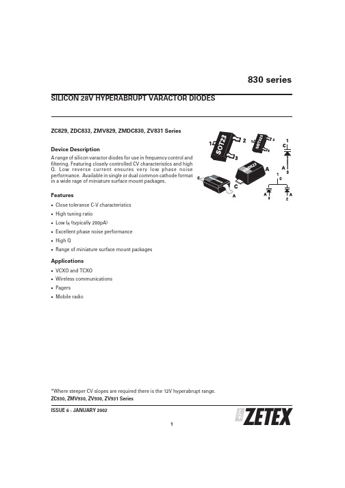
ZC829, ZDC833, ZMV829, ZMDC830, ZV831 Series Device DescriptionA range of silicon varactor diodes for use in frequency control and filtering.Featuring closely controlled CV characteristics and high Q.Low reverse current ensures very low phase noise performance.Available in single or dual common cathode format in a wide rage of miniature surface mount packages.Features·Close tolerance C-V characteristics ·High tuning ratio ·Low I R (typically 200pA)·Excellent phase noise performance ·High Q·Range of miniature surface mount packagesApplications·VCXO and TCXO·Wireless communications ·Pagers ·Mobile radio*Where steeper CV slopes are required there is the 12V hyperabrupt range.ZC930, ZMV930, ZV930, ZV931 Series 830 seriesISSUE 6 - JANUARY 20021SILICON 28V HYPERABRUPT VARACTOR DIODES830 seriesISSUE 6 - JANUARY 20022PARTCapacitance (pF)V R =2V,f=1MHzMin Q V R =3V f=50MHzCapacitance RatioC 2/C 20at f=1MHzMIN.NOM.MAX.MIN.MAX.829A 7.388.29.02250 4.3 5.8829B 7.798.28.61250 4.3 5.8830A 9.010.011.0300 4.5 6.0830B 9.510.010.5300 4.5 6.0831A 13.515.016.5300 4.5 6.0831B 14.2515.015.75300 4.5 6.0832A 19.822.024.2200 5.0 6.5832B 20.922.023.1200 5.0 6.5833A 29.733.036.3200 5.0 6.5833B 31.3533.034.65200 5.0 6.5834A 42.347.051.7200 5.0 6.5834B 44.6547.049.35200 5.0 6.5835A 61.268.074.8100 5.0 6.5835B 64.668.071.4100 5.0 6.5836A 90.0100.0110.0100 5.0 6.5836B95.0100.0105.0100 5.06.5TUNING CHARACTERISTICS at Tamb = 25°CPARAMETER SYMBOLMAX UNIT Forward currentI F 200mA Power dissipation at T amb =25ЊC SOT23P tot 330mW Power dissipation at T amb =25ЊC SOD323P tot 330mW Power dissipation at T amb =25ЊC SOD523P tot250mW Operating and storage temperature range-55to +150ЊCABSOLUTE MAXIMUM RATINGSPARAMETERCONDITIONS MIN.TYP.MAX.UNIT Reverse breakdown voltage I R =10uA 25V Reverse voltage leakageV R =20V 0.220nA Temperature coefficient of capacitanceV R =3V,f =1MHz300400ppCm/ЊCELECTRICAL CHARACTERISTICS at Tamb = 25°C830 seriesTYPICAL CHARACTERISTICSISSUE 6 - JANUARY 20023830 seriesISSUE 6 - JANUARY 20024O R D E R C O D E S A N D P A R T M A R K I N GR E E L C O D ER E E L S I Z ET A P E W I D T HQ U A N T I T Y P E R R E E LT A7i n c h (180m m )8m m3000T C13i n c h (330m m )8m m 10000T A P E A N D R E E L I N F O R M A T I O NT h e o r d e r c o d e s a r e s h o w n a s T A w h i c h i s f o r 7i n c h r e e l s .F o r 13i n c h r e e l s s u b s t i t u t e T C i n p l a c e o f T A i n t h e o r d e r c o d e .ISSUE 6 - JANUARY 20025830 seriesSOT23 PACKAGE DIMENSIONSSOD323 PACKAGE DIMENSIONSZetex plcFields New Road ChaddertonOldham, OL9 8NP United KingdomTelephone (44) 161 622 4422Fax: (44) 161 622 4420Zetex GmbHStreitfeldstraße 19D-81673 München GermanyTelefon: (49) 89 45 49 49 0Fax: (49) 89 45 49 49 49Zetex Inc700 Veterans Memorial Hwy Hauppauge, NY11788USATelephone: (631) 360 2222Fax: (631) 360 8222Zetex (Asia) Ltd3701-04Metroplaza, Tower 1Hing Fong Road Kwai Fong Hong KongTelephone: (852) 26100 611Fax: (852) 24250 494These offices are supported by agents and distributors in major countries world-wide.This publication is issued to provide outline information only which (unless agreed by the Company in writing)may not be used,applied or reproduced for any purpose or form part of any order or contract or be regarded as a representation relating to the products or services concerned.The Company reserves the right to alter without notice the specification,design,price or conditions of supply of any product or service.For the latest product information,log on to©Zetex plc 2001830 series6ISSUE 6 - JANUARY 2002DIM MILLIMETRES MIN.MAX A ᎏ0.800A10.0000.100A20.6000.800b10.1600.300c 0.0800.220D 0.7000.900E 1.500 1.700E1 1.100 1.300L 0.2000.400L10.1700.230⍜1Њ4Њ10ЊSOD523 PACKAGE DIMENSIONSSOD323 PACKAGE DIMENSIONS。
UPD780024AGB-xxx-8EU中文资料

Document No. U14042EJ4V0DS00 (4th edition) Date Published December 2002 N CP(K) Printed in Japan
The mark
shows major revised points.
ቤተ መጻሕፍቲ ባይዱ
©
©
2000
µPD780021A, 780022A, 780023A, 780024A, 780021AY, 780022AY, 780023AY, 780024AY
The µPD780021A, 780022A, 780023A, and 780024A are members of the µPD780024A Subseries of the 78K/0 Series. Only selected functions of the existing µPD78054 Subseries are provided, and the serial interface is enhanced. The µPD780021AY, 780022AY, 780023AY, and 780024AY are the µPD780024A Subseries with a multimaster supporting I2C bus interface, which makes them suitable for AV equipment. Flash memory versions, the µPD78F0034A, 78F0034B, 78F0034AY, and 78F0034BY, that can operate in the same power supply voltage range as the mask ROM versions, and various development tools, are also available. Detailed function descriptions are provided in the following user’s manuals. Be sure to read them before designing. µPD780024A, 780034A, 780024AY, 780034AY Subseries User’s Manual: U14046E 78K/0 Series Instructions User’s Manual: U12326E
- 1、下载文档前请自行甄别文档内容的完整性,平台不提供额外的编辑、内容补充、找答案等附加服务。
- 2、"仅部分预览"的文档,不可在线预览部分如存在完整性等问题,可反馈申请退款(可完整预览的文档不适用该条件!)。
- 3、如文档侵犯您的权益,请联系客服反馈,我们会尽快为您处理(人工客服工作时间:9:00-18:30)。
•LOW NOISE FIGURE:NF = 1.4 dB TYP at f = at 12 GHz•HIGH ASSOCIATED GAIN:G A = 10 dB TYP at f = 12 GHz•GATE WIDTH: W G = 280 µm •GATE LENGTH: L G = 0.3 µmDESCRIPTIONNEC's NE674 is a L to Ku Band low noise GaAs MESFET. This device features a low noise figure with high associated gain,employing a recessed 0.3 micron gate and triple epitaxial technology. The active area of the chip is covered with S i D 2and S i3N 4 for scratch protection and surface stability. This device is suitable for both amplifier and oscillator applications.This device is housed in a solder sealed hermetic, metal ceramic package for high reliability in space applications.PART NUMBER NE67400PACKAGE OUTLINENE67483B SYMBOLSPARAMETERS AND CONDITIONS UNITS MINTYP MAX NFNoise Figure at V DS = 3 V, I D = 10 mA, f = 4 GHzdB 0.6 f = 12 GHz dB 1.4 1.6G AAssociated Gain at V DS = 3 V I D = 10 mA, f = 4 GHzdB 14.0 f = 12 GHz dB8.510.0P 1dBOutput Power at 1 dB Gain Compression Point, f = 12 GHz,V DS = 3 V, I DS = 30 mAdBm 14.5I DSS Saturated Drain Current at V DS = 3 V, V GS = 0 V mA 2040120V GS(OFF)Gate to Source Cut Off Voltage at V DS = 3 V, I D = 100 µA V -0.5-1.1-3.5g m Transconductance at V DS = 3 V, I D = 10 mA mS 2050100I GSO Gate to Source Leakage Current at V GS = -5 VµA 1.010R TH (CH-C)Thermal Resistance (Channel-to-Case) NE67400°C/W 190 NE67483B°C/W450ELECTRICAL CHARACTERISTICS (T A = 25°C)California Eastern LaboratoriesN o i s e F i g u r e , N F (d B )Frequency, f (GHz)A s s o c i a t e d G a i n , G A , (dB )2.03.01.0012162024841246810142030元器件交易网FREQ.NF OPT G A ΓOPT (GHz)(dB)(dB)MAG ANG Rn/5020.5517.00.81370.5730.5815.20.75530.5140.6014.00.70690.4450.6813.20.67830.3760.7612.60.65970.3170.8512.00.641110.2580.9311.50.641230.199 1.0311.00.641360.1410 1.1510.70.641480.1011 1.2610.30.641610.0612 1.4010.00.631730.0513 1.559.60.62-1730.0514 1.709.20.60-1590.0815 1.849.00.57-1450.15162.048.60.53-1290.2317 2.188.30.46-1130.34182.358.00.38-950.44SYMBOLSPARAMETERS UNITS RATINGSV DS Drain to Source Voltage V 5.0V GD Gate to Drain Voltage V –6.0I DS Drain Current mA I DSS T CH Channel Temperature °C 175T STG Storage Temperature °C -65 to +175P TTotal Power Dissipation NE67483B mW 270NE67400mW400TYPICAL PERFORMANCE CURVES (T A = 25°C)Ambient Temperature, T A (°C)TOTAL POWER DISSIPATION vs.AMBIENT TEMPERATURENE67400, NE67483BABSOLUTE MAXIMUM RATINGS 1 (T A = 25°C)TYPICAL NOISE PARAMETERS (T A = 25°C)V DS = 3 V, I DS = 10 mA (NE67483B)DRAIN CURRENT vs.DRAIN TO SOURCE VOLTAGED r a i n C u r r e n t , I D S (m A )Note:1. Operation in excess of any one of these conditions may result in permanent damage.Drain to Source Voltage, V DS (V)T o t a l P o w e r D i s s i p a t i o n , P T (m W )SYMBOLSPARAMETERS UNITS MIN TYP MAX V DS Drain to Source VoltageV 34I D Drain Current mA 1030P INInput PowerdBm15RECOMMENDED OPERATING CONDITIONS (T A = 25°C)30020040010005010015020040302010元器件交易网TYPICAL COMMON SOURCE SCATTERING PARAMETERS (T A = 25°C)NE67400, NE67483BTYPICAL PERFORMANCE CURVES (T A = 25°C)Gate to Source Voltage, V GS (V)DRAIN CURRENT vs.GATE TO SOURCE VOLTAGED r a i n C u r r e n t , I D S (m A )NE67483BS 11V DS = 3 V, I D = 10 mA Start 500 MHz,Stop 18 GHZ,Step 500 MHz Marker 1 : 2 GHz 2 : 4 GHz 3 : 8 GHz 4 : 12 GHz 5 : 16 GHzS 2240503020100-1.0-2.0元器件交易网FREQUENCY S 11S 21S 12S 22KMAG 1 MHz MAG ANG MAG ANG MAG ANG MAG ANG (dB)NE67400, NE67483BNote:1.Gain Calculations:NE67483BV DS = 3 V, I DS = 10 mAMAG = Maximum Available GainMSG = Maximum Stable Gain5000.992 -11.4 3.091169.60.01181.80.729 -6.90.1331.2510000.961-21.7 3.045159.3 0.02274.60.721-14.00.3223.9815000.985-32.1 3.029150.2 0.03267.10.714-21.00.1227.962000 0.960-42.5 2.941141.10.04159.8 0.709-27.60.2123.472500 0.930 -53.1 2.914130.60.04953.30.696-34.10.3020.8530000.934 -61.7 2.795123.10.05646.50.687 -40.40.2720.6635000.885-70.6 2.662113.50.06239.60.672 -47.10.4417.7540000.855 -81.8 2.568104.4 0.068 34.70.657 -53.60.4816.3645000.876 -89.4 2.53795.50.07129.30.651-59.90.4216.8050000.830-97.3 2.43688.70.07623.40.637-66.30.5415.0755000.818-106.0 2.33380.90.07717.60.630-72.40.5814.3760000.817-111.4 2.25174.20.08014.00.623-78.60.5813.9765000.786 -120.2 2.13266.20.0809.30.613-84.70.7012.8070000.781-126.4 2.10059.20.081 5.90.619-90.50.7012.6375000.772 -133.0 2.02852.60.081 1.60.616-96.00.7412.148000 0.763-140.2 1.98844.90.079-2.10.614-101.60.7811.828500 0.752-145.6 1.92939.30.082-4.40.619-106.80.7811.4290000.734-152.9 1.85431.60.080-7.00.621-112.30.8710.8495000.716-158.2 1.81525.80.079-9.80.620-117.70.9510.41100000.695-164.0 1.75820.00.081-11.30.618-122.7 1.0112.83105000.685-169.5 1.71414.10.079-14.20.628 -127.7 1.0611.85110000.672-174.5 1.6667.70.079-16.60.624-133.5 1.1311.00115000.661179.4 1.657 1.20.080-18.30.624-138.4 1.1510.83120000.649 174.4 1.624-4.50.080-19.6 0.633-143.9 1.1610.63125000.633 169.1 1.597-11.40.080-21.6 0.629 -149.3 1.2410.04130000.614162.3 1.577-17.30.082-24.00.638-153.9 1.249.88135000.594156.9 1.542-24.1 0.082-24.40.646 -159.1 1.289.53140000.567 151.1 1.500-30.00.085 -27.70.651 -164.0 1.348.99145000.543143.5 1.483 -36.10.088-28.70.662-168.7 1.318.95150000.536138.2 1.462 -41.90.089-31.60.668-174.0 1.308.87155000.512131.0 1.455-47.90.094 -34.70.670-178.5 1.288.74160000.489123.7 1.451-54.10.097-37.30.679 176.3 1.248.79165000.465116.9 1.433 -60.5 0.100-40.8 0.681172.0 1.278.45170000.451108.3 1.441 -67.50.102 -44.1 0.688167.4 1.228.67175000.418100.7 1.408-74.60.106 -48.5 0.686 162.6 1.288.05180000.38791.91.404-81.60.115-52.00.690158.21.228.06MAG =|S 21||S 12|K - 1 ).2(K ±∆ = S 11 S 22 - S 21 S 12When K ≤ 1, MAG is undefined and MSG values are used.MSG =|S 21||S 12|, K = 1 + | ∆ | - |S 11| - |S 22|2222 |S 12 S 21|,元器件交易网FREQUENCY S 11S 21S 12S 22K MAG 1 MHz MAG ANG MAG ANG MAG ANG MAG ANG (dB)NE67400, NE67483BNote:1.Gain Calculations:NE67483BV DS = 3 V, I DS = 20 mAMAG = Maximum Available GainMSG = Maximum Stable Gain5000.999 -10.8 3.834169.50.01082.50.685 -6.80.0000.0010000.998-21.9 3.746160.0 0.02073.60.680-13.80.0000.0015000.996-33.4 3.694149.1 0.02966.40.667-20.90.0834.722000 0.987-43.8 3.630140.20.03759.9 0.663-27.40.1029.652500 0.968 -54.5 3.552130.30.04554.10.651-33.80.1625.4830000.948 -63.8 3.417121.70.05247.60.638 -40.20.2322.8635000.923-73.4 3.265112.50.05643.20.627 -46.70.2820.7640000.890 -84.3 3.107103.1 0.062 36.60.612 -52.90.3718.7045000.885 -93.2 3.06793.90.06530.50.605-59.30.3818.3750000.860-100.9 2.92987.30.06726.00.592-65.40.4417.0555000.840-109.0 2.80479.60.07021.30.586-71.30.4916.0960000.828-115.7 2.69472.90.07118.90.580-77.60.5115.4265000.811 -123.8 2.53864.70.07313.50.572-83.40.5914.4570000.797-130.5 2.50057.90.07310.60.578-88.90.6114.1175000.776 -137.6 2.39951.10.0738.40.575-94.20.6813.348000 0.780-144.3 2.34943.60.074 5.40.575-99.80.6713.248500 0.754-150.5 2.27138.00.075 2.80.581-104.80.7312.5690000.738-157.3 2.17529.90.0750.50.584-110.10.8011.9795000.720-162.7 2.12924.70.077-1.90.582-115.20.8311.53100000.693-169.1 2.05018.50.078-3.40.585-120.00.9210.89105000.677-174.1 1.99912.70.077-5.50.591 -125.00.9910.54110000.661-179.3 1.943 6.60.078-6.60.593-131.1 1.0213.04115000.649174.6 1.9230.10.080-8.00.593-135.6 1.0312.69120000.627 169.6 1.884-5.80.081-10.2 0.600-141.0 1.0811.95125000.608 163.6 1.850-12.60.083-12.1 0.603 -146.5 1.1211.43130000.594157.6 1.820-18.50.086-14.10.615-150.9 1.0911.48135000.563151.3 1.778-25.2 0.087-15.90.621 -156.1 1.1510.74140000.536 145.7 1.730-31.30.092 -19.10.632 -160.9 1.1510.42145000.513138.3 1.708 -37.20.095-21.20.641-165.7 1.1410.29150000.499131.9 1.678 -43.10.098-24.10.648-170.8 1.1210.24155000.467125.3 1.665-49.40.103 -27.50.657-175.2 1.1110.10160000.456117.8 1.654-55.40.105-31.50.666 179.2 1.0710.30165000.426109.8 1.636 -61.9 0.111-34.6 0.668175.0 1.0810.01170000.401101.8 1.631 -68.80.114 -39.1 0.683170.1 1.0410.34175000.37392.7 1.599-76.10.118 -43.4 0.679 165.3 1.089.58180000.34482.31.595-83.00.125-49.50.691160.41.0310.05MAG =|S 21||S 12|K - 1 ).2(K ±∆ = S 11 S 22 - S 21 S 12When K ≤ 1, MAG is undefined and MSG values are used.MSG =|S 21||S 12|, K = 1 + | ∆ | - |S 11| - |S 22|2222 |S 12 S 21|,元器件交易网FREQUENCY S 11S 21S 12S 22KMAG 1 MHz MAG ANG MAG ANG MAG ANG MAG ANG (dB)NE67400, NE67483BNote:1.Gain Calculations:NE67483BV DS = 3 V, I DS = 30 mAMAG = Maximum Available GainMSG = Maximum Stable Gain5000.999 -11.1 4.104169.40.00980.00.672 -6.70.0000.0010000.998-22.3 4.015159.5 0.01975.60.665-13.70.0439.4815000.991-34.0 3.946148.9 0.02668.00.655-20.90.0831.922000 0.977-44.6 3.862139.70.03560.4 0.650-27.20.1427.602500 0.962 -55.3 3.789129.70.04254.80.638-33.70.1825.1330000.937 -64.9 3.621121.30.04847.90.625 -39.70.2622.4635000.909-74.5 3.459111.80.05342.50.613 -46.40.3420.4140000.878 -85.4 3.291102.7 0.057 38.00.599 -52.30.4118.6845000.870 -94.5 3.23793.40.06031.20.592-58.80.4318.2150000.845-102.2 3.08786.80.06226.80.579-64.80.5016.9955000.824-110.4 2.95179.10.06624.10.574-70.70.5416.0760000.814-117.0 2.83072.40.06621.30.568-76.80.5615.4565000.793 -125.4 2.66664.40.06716.60.560-82.60.6514.4670000.780-131.7 2.62257.50.06914.30.566-88.00.6714.1175000.759 -139.0 2.51150.80.06911.40.563-93.20.7513.388000 0.759-145.8 2.45643.20.0699.20.565-98.70.7413.208500 0.738-151.7 2.37637.80.070 6.50.570-103.80.8012.6490000.718-158.5 2.27129.70.070 5.10.574-109.10.8812.0095000.702-164.1 2.22524.50.073 3.00.575-114.20.8911.64100000.676-170.0 2.13918.60.073 2.60.577-119.00.9811.02105000.663-175.2 2.08812.60.073-0.10.585 -123.7 1.0213.62110000.644179.6 2.029 6.40.076-0.60.586-129.9 1.0512.92115000.630173.5 2.0040.00.078-2.40.584-134.4 1.0712.49120000.613 168.6 1.958-5.80.080-4.6 0.595-139.9 1.0912.12125000.594 162.7 1.930-12.50.081-7.0 0.599 -145.1 1.1211.64130000.577156.7 1.890-18.30.085-7.60.608-149.7 1.0911.60135000.549150.2 1.850-25.1 0.088-9.60.616 -154.8 1.1211.14140000.523 144.3 1.800-31.00.092 -13.30.626 -159.8 1.1410.69145000.496137.0 1.772 -37.10.096-16.10.638-164.3 1.1110.61150000.486131.1 1.741 -42.90.101-19.40.645-169.7 1.0710.77155000.455123.6 1.733-49.10.106 -21.70.653-174.0 1.0510.74160000.439117.0 1.718-55.10.106-26.20.664 -179.3 1.0510.70165000.416108.5 1.693 -61.6 0.113-30.1 0.668176.2 1.0310.68170000.390100.0 1.697 -68.50.118 -34.4 0.684171.50.9700.00175000.36492.3 1.654-75.70.123 -39.2 0.679 166.8 1.0110.78180000.33780.61.652-82.80.129-45.00.692162.00.9600.00MAG =|S 21||S 12|K - 1 ).2(K ±∆ = S 11 S 22 - S 21 S 12When K ≤ 1, MAG is undefined and MSG values are used.MSG =|S 21||S 12|, K = 1 + | ∆ | - |S 11| - |S 22|2222 |S 12 S 21|,元器件交易网OUTLINE DIMENSIONS (Units in mm)PACKAGE OUTLINE 83BPART I DSS (mA)PACKAGE NUMBER OUTLINE NE6740020 to 12000 (CHIP)NE67483B20 to 12083BORDERING INFORMATIONNE67400, NE67483B0.1+0.07 -0.031.88 ±CHIP DIMENSIONS (Units in µm)NE67400EXCLUSIVE NORTH AMERICAN AGENT FOR RF, MICROWAVE & OPTOELECTRONIC SEMICONDUCTORS• Headquarters • 4590 Patrick Henry Drive • Santa Clara, CA 95054-1817 • (408) 988-3500 • Telex 34-6393 • FAX (408) 988-0279PRINTED IN USA ON RECYCLED PAPER -3/98DATA SUBJECT TO CHANGE WITHOUT NOTICELife Support ApplicationsThese NEC products are not intended for use in life support devices, appliances, or systems where the malfunction of these products can reasonably be expected to result in personal injury. The customers of CEL using or selling these products for use in such applications do so at their own risk and agree to fully indemnify CEL for all damages resulting from such improper use or sale.元器件交易网。