MDM-15PCBRP-A174中文资料
pcm1794a 手册

pcm1794a 手册摘要:1.pcm1794a 手册简介2.pcm1794a 的主要功能3.pcm1794a 的使用方法4.pcm1794a 的维护与保养5.结论正文:【1.pcm1794a 手册简介】pcm1794a 手册是一本详细介绍pcm1794a 设备使用与维护的指南。
它为使用者提供了设备的操作方法、性能特点、注意事项等方面的详尽信息,旨在帮助用户更好地了解和掌握pcm1794a 的使用技巧,充分发挥其性能优势。
【2.pcm1794a 的主要功能】pcm1794a 是一款具有高性能、高稳定性的设备,主要用于数据采集、处理和传输。
其主要功能包括:- 高速数据采集:pcm1794a 可以实时采集模拟信号,具有高精度、高采样率的特性。
- 数据处理:设备内部集成了多种数据处理功能,如滤波、积分、求和等,可满足各种数据处理需求。
- 数据传输:通过串行或并行接口,pcm1794a 可以方便地将采集到的数据传输到其他设备或计算机系统中。
【3.pcm1794a 的使用方法】使用pcm1794a 时,首先需要对其进行配置,包括设置采样率、数据宽度、触发模式等参数。
接着,通过编程或手动操作,将pcm1794a 与计算机或其他设备相连接,开始进行数据采集、处理和传输。
在操作过程中,应遵循设备手册中的安全规定,以确保设备的安全稳定运行。
【4.pcm1794a 的维护与保养】为了保证pcm1794a 的性能和寿命,用户需要定期对其进行维护和保养。
具体措施包括:- 清洁:定期用柔软的布擦拭设备表面,去除灰尘和污垢。
- 检查:定期检查设备的连接线、接口等部件,确保其完好无损。
- 校准:根据实际需要,定期对设备进行校准,确保其性能稳定。
【5.结论】总之,pcm1794a 手册为用户提供了详细的设备使用和维护信息,有助于充分发挥pcm1794a 的性能优势。
PCM1794DBG4中文资料

SAMPLING, ADVANCEDDIGITALĆTOĆANALOGD Dual-Supply Operation:ESD damage can range from subtle performance degradation to complete device failure. Precision integrated circuits may be more susceptible to damage because very small parametric changes could cause the device not to meet its published specifications.PRODUCTIONconform to specificationsProduction processingPACKAGING INFORMATIONOrderable Device Status (1)Package Type Package Drawing Pins Package Qty Eco Plan (2)Lead/Ball Finish MSL Peak Temp (3)PCM1794DB ACTIVE SSOP DB 2847Green (RoHS &no Sb/Br)CU NIPDAU Level-1-260C-UNLIM PCM1794DBG4ACTIVE SSOP DB 2847Green (RoHS &no Sb/Br)CU NIPDAU Level-1-260C-UNLIM PCM1794DBR ACTIVE SSOP DB 282000Green (RoHS &no Sb/Br)CU NIPDAU Level-1-260C-UNLIM PCM1794DBRG4ACTIVESSOPDB282000Green (RoHS &no Sb/Br)CU NIPDAULevel-1-260C-UNLIM(1)The marketing status values are defined as follows:ACTIVE:Product device recommended for new designs.LIFEBUY:TI has announced that the device will be discontinued,and a lifetime-buy period is in effect.NRND:Not recommended for new designs.Device is in production to support existing customers,but TI does not recommend using this part in a new design.PREVIEW:Device has been announced but is not in production.Samples may or may not be available.OBSOLETE:TI has discontinued the production of the device.(2)Eco Plan -The planned eco-friendly classification:Pb-Free (RoHS),Pb-Free (RoHS Exempt),or Green (RoHS &no Sb/Br)-please check /productcontent for the latest availability information and additional product content details.TBD:The Pb-Free/Green conversion plan has not been defined.Pb-Free (RoHS):TI's terms "Lead-Free"or "Pb-Free"mean semiconductor products that are compatible with the current RoHS requirements for all 6substances,including the requirement that lead not exceed 0.1%by weight in homogeneous materials.Where designed to be soldered at high temperatures,TI Pb-Free products are suitable for use in specified lead-free processes.Pb-Free (RoHS Exempt):This component has a RoHS exemption for either 1)lead-based flip-chip solder bumps used between the die and package,or 2)lead-based die adhesive used between the die and leadframe.The component is otherwise considered Pb-Free (RoHS compatible)as defined above.Green (RoHS &no Sb/Br):TI defines "Green"to mean Pb-Free (RoHS compatible),and free of Bromine (Br)and Antimony (Sb)based flame retardants (Br or Sb do not exceed 0.1%by weight in homogeneous material)(3)MSL,Peak Temp.--The Moisture Sensitivity Level rating according to the JEDEC industry standard classifications,and peak solder temperature.Important Information and Disclaimer:The information provided on this page represents TI's knowledge and belief as of the date that it is provided.TI bases its knowledge andbelief on information provided by third parties,and makes no representation or warranty as to the accuracy of such information.Efforts are underway to better integrate information from third parties.TI has taken and continues to take reasonable steps to provide representative and accurate information but may not have conducted destructive testing or chemical analysis on incoming materials and chemicals.TI and TI suppliers consider certain information to be proprietary,and thus CAS numbers and other limited information may not be available for release.In no event shall TI's liability arising out of such information exceed the total purchase price of the TI part(s)at issue in this document sold by TI to Customer on an annual basis.PACKAGE OPTION ADDENDUM30-Oct-2006TAPE AND REEL INFORMATION*All dimensions are nominalDevicePackage Type Package Drawing Pins SPQReel Diameter (mm)Reel Width W1(mm)A0(mm)B0(mm)K0(mm)P1(mm)W (mm)Pin1Quadrant PCM1794DBR SSOPDB282000330.017.48.510.8 2.412.016.0Q1*All dimensions are nominalDevice Package Type Package Drawing Pins SPQ Length(mm)Width(mm)Height(mm) PCM1794DBR SSOP DB282000336.6336.628.6IMPORTANT NOTICETexas Instruments Incorporated and its subsidiaries(TI)reserve the right to make corrections,modifications,enhancements,improvements, and other changes to its products and services at any time and to discontinue any product or service without notice.Customers should obtain the latest relevant information before placing orders and should verify that such information is current and complete.All products are sold subject to TI’s terms and conditions of sale supplied at the time of order acknowledgment.TI warrants performance of its hardware products to the specifications applicable at the time of sale in accordance with TI’s standard warranty.Testing and other quality control techniques are used to the extent TI deems necessary to support this warranty.Except where mandated by government requirements,testing of all parameters of each product is not necessarily performed.TI assumes no liability for applications assistance or customer product design.Customers are responsible for their products and applications using TI components.To minimize the risks associated with customer products and applications,customers should provide adequate design and operating safeguards.TI does not warrant or represent that any license,either express or implied,is granted under any TI patent right,copyright,mask work right, or other TI intellectual property right relating to any combination,machine,or process in which TI products or services are rmation published by TI regarding third-party products or services does not constitute a license from TI to use such products or services or a warranty or endorsement e of such information may require a license from a third party under the patents or other intellectual property of the third party,or a license from TI under the patents or other intellectual property of TI.Reproduction of TI information in TI data books or data sheets is permissible only if reproduction is without alteration and is accompanied by all associated warranties,conditions,limitations,and notices.Reproduction of this information with alteration is an unfair and deceptive business practice.TI is not responsible or liable for such altered rmation of third parties may be subject to additional restrictions.Resale of TI products or services with statements different from or beyond the parameters stated by TI for that product or service voids all express and any implied warranties for the associated TI product or service and is an unfair and deceptive business practice.TI is not responsible or liable for any such statements.TI products are not authorized for use in safety-critical applications(such as life support)where a failure of the TI product would reasonably be expected to cause severe personal injury or death,unless officers of the parties have executed an agreement specifically governing such use.Buyers represent that they have all necessary expertise in the safety and regulatory ramifications of their applications,and acknowledge and agree that they are solely responsible for all legal,regulatory and safety-related requirements concerning their products and any use of TI products in such safety-critical applications,notwithstanding any applications-related information or support that may be provided by TI.Further,Buyers must fully indemnify TI and its representatives against any damages arising out of the use of TI products in such safety-critical applications.TI products are neither designed nor intended for use in military/aerospace applications or environments unless the TI products are specifically designated by TI as military-grade or"enhanced plastic."Only products designated by TI as military-grade meet military specifications.Buyers acknowledge and agree that any such use of TI products which TI has not designated as military-grade is solely at the Buyer's risk,and that they are solely responsible for compliance with all legal and regulatory requirements in connection with such use. TI products are neither designed nor intended for use in automotive applications or environments unless the specific TI products are designated by TI as compliant with ISO/TS16949requirements.Buyers acknowledge and agree that,if they use any non-designated products in automotive applications,TI will not be responsible for any failure to meet such requirements.Following are URLs where you can obtain information on other Texas Instruments products and application solutions:Products ApplicationsAmplifiersAudioData Converters AutomotiveDSP BroadbandClocks and Timers Digital ControlInterface MedicalLogic MilitaryPower Mgmt Optical NetworkingMicrocontrollers SecurityRFID TelephonyRF/IF and ZigBee®Solutions Video&ImagingWirelessMailing Address:Texas Instruments,Post Office Box655303,Dallas,Texas75265Copyright©2008,Texas Instruments Incorporated元器件交易网。
aten CS-1742 1744 说明书
用户手册CS-1742 CS-1744CS-1742/CS-1744 User ManualFCC信息本产品是通过FCC认证的A级产品。
在居住环境使用可能会对通讯造成干扰,因此建议用户可采取适当的防护措施。
本产品已经过测试,完全符合A级电子设备要求和FCC认证的第15部分规范。
这些规范是为了在商业环境下使用该设备,而能避免有害干扰,并提供有效保护所规范的规定。
该设备会产生并辐射电磁波,如果用户未能按照该用户手册的说明以进行安装和使用,将可能对通讯造成有害干扰,如果在居住区域使用而造成此种情况,用户将自行解决并负相关责任。
RoHS该产品符合RoHS规范。
iiCS-1742/CS-1744 User Manual 用户注意事项制造商有修改与变更手册所包含的信息、文件和规格表的权利,且不需事前通知。
制造商不会保证、明示、暗示或法定声明其内容或特别否认其对于特殊用途的可销售性和适用性。
本手册所描述的任何被销售与授权的制造商软件亦同。
如果在购买后发现软件程序有瑕疵,购买者(及非制造商、其经销商或其购买商家)将需承担所有因软件瑕疵所造成的必要服务费用、维修责任及任何偶然事件或间接损害。
制造商并不担负任何未经授权调整本设备所造成的收音机及/或电视干扰的责任,用户必须自行修正干扰。
操作前如未正确选择操作电压的设定,制造商将不担负因此所导致任何损害的责任。
使用前请务必确认电压设置为正确的。
iiiCS-1742/CS-1744 User Manual安全说明概述u请阅读所有说明,并作为以后参考。
u请遵循设备上的所有警告与指示。
u勿将本设备放置于任何不平稳的平面上(如推车、架子、或桌子等),如果本设备掉落会造成严重的损坏。
u请勿在接近水的地方使用本设备。
u请勿将本设备放置于散热器或是暖气设备旁边或其上方。
u本设备外壳配有槽孔可以散热及通风,为了确保操作中防止过热,勿将开孔处堵塞或遮盖住。
u本设备不可放置于软的表面上(如床、沙发、毛毯等),将会堵塞风扇开孔,同样也不能放在密封的环境下,除非已提供了适当的通风,才可以放置。
UA741中文资料
UA741中文资料pdf 应用电路(组图) uA741M,uA741I,uA741C(单运放)是高增益运算放大器,用于军事,工业和商业应用.这类单片硅集成电路器件提供输出短路保护和闭锁自由运作。
这些类型还具有广泛的共同模式,差模信号范围和低失调电压调零能力与使用适当的电位。
uA741M,uA741I,uA741C芯片引脚和工作说明:1和5为偏置(调零端),2为正向输入端,3为反向输入端,4接地,6为输出,7接电源 8空脚温度等级Package 封装 Part Number零件型号 Temperature Range 工作温度范围 N D UA741C 0℃ - +70℃ ? ? UA741I -40℃ - +105℃ ? ? UA741M -55℃ - +125℃ ? ? 例如 : UA741CN ABSOLUTE MAXIMUM RATINGS最大额定值 Symbol符号 Parameter参数 UA741M UA741I UA741C Unit单位 VCC Supply voltage电源电压±22V Vid Differential Input Voltage差分输入电压±30V Vi Input Voltage输入电压±15V Ptot Power Dissipation功耗500mW Toper Output Short-circuit Duration输出短路持续时间 Infinite无限制Operating Free-air Temperature Range工作温度 -55 to +125 -40 to +105 0 to +70℃Tstg Storage Temperature Range储存温度范围 -65 to +150 ELECTRICAL CHARACTERISTICS VCC = ±15V, Tamb = +25°C (unless otherwise specified) 电气特性虚拟通道连接= ± 15V , Tamb = 25 ℃(除非另有说明) Symbol符号Parameter参数最小. 典型. 最大. Unitd单位 Vio Input Offset Voltage (Rs ≤ 10K?)输入失调电压 - mV Tamb = +25℃ - 1 5 Tmin ≤ Tamb ≤ Tmax - - 6 Iio Input Offset Current 输入失调电流 nA Tamb = +25℃ - 2 30 Tmin ≤ Tamb ≤ Tmax - - 70 Iib Input Bias Current 输入偏置电流 nA Tamb = +25℃ - 10 100 Tmin ≤ Tamb ≤ Tmax - - 200 Avd Large Signal Voltage Gain (Vo=±10V, RL=2K?) 大信号电压增益 V/mV Tamb = +25℃ 50 200 - Tmin ≤ Tamb ≤ Tmax 25 -SVR Supply Voltage Rejection Ratio (Rs ≤ 10K?)电源电压抑制比 dB Tamb = +25℃ 77 90 - Tmin ≤ Tamb ≤ Tmax 77 - - ICC Supply Current, no load 电源电流(空载) mA Tamb = +25℃ - 1.7 2.8 Tmin ≤ Tamb ≤ Tmax - - 3.3 Vicm Input Common Mode Voltage Range 输入共模电压范围 V Tamb = +25℃±12 - - Tmin ≤ Tamb ≤ Tmax ±12 - - CMR Common Mode Rejection Ratio (RS ≤ 10K?)共模抑制比 dB Tamb = +25℃ 70 90 - Tmin ≤ Tamb ≤ Tmax 70 - - IOS Output short Circuit Current输出短路电流 10 25 40 mA ±Vopp Output Voltage Swing输出电压摆幅 Tamb=+25℃ RL=10K? 12 14 - V RL=2K? 10 13 - Tmin≤Tamb ≤Tmax RL=10K? 12 - - RL=2K? 10 - - SR Slew Rate Vi=±10V,RL=2K?,CL=100pF,unity Gain 转换率单位增益 0.25 0.5 - V/μs tr Rise Time Vi = ±20mV, RL =2K?,CL = 100pF, u- 0.3 - μs nity Gain 上升时间单位增益Kov Overshoot Vi=20mV,RL=2K?,CL=100pF,unity Gain 超虚拟单位增益 - 5 - % Ri Input Resistance输入阻抗 0.3 2 - M? GBP Gain Bandwith Product Vi = 10mV, RL =2K?,CL= 100pF, f =100kHz 带宽增益 0.7 1 - MHz THD Total Harmonic Distortion f = 1kHz, Av = 20dB, RL=2K?,Vo=2Vpp, CL=100pF,Tamb=+25℃总谐波失真 - 0.06 - % en Equivalent Input Noise Voltage f=1kHz,Rs=100?等效输入噪声电压 - 23 - nV√Hz ¢m Phase Margin 相位裕度 - 50 - Degrees UA741/ LM741应用电路:图 6 12V的电池监视器图7 低功耗放大器图8 741驱动三极管的5瓦功率放大器图9 自动感光电路图。
HighPoint RocketRAID 1740 SATA Raid卡部件规格书说明书

HighPoint Technologies, Inc. (Confidential)HighPoint RocketRAID HighPoint RocketRAID 17401740 SA SATA TA TA Raid 卡部件规格书卡部件规格书REV REV::1.0(以下简称“本规格书”)目 录录一、本规格书适用产品及型号产品型号: HighPoint RocketRAID 1740二、 技术规格产品描述 处理器无SATA 控制器 Marvell 6042板载内存 无 扩展内存 无PCI PCI 32bit@33/66 MHz接口 3.3/5V 通道类型 SATA150通道数量 4自动修复 支持RAID 级别 0,1,5,10,JBOD条带大小设置 支持 控制器cache 控制 不支持 硬盘cache 控制不支持 SAF-TE 支持初始化模式 可选:1、不用初始化,2、正常初始化。
Online Array Expansion支持Online Array Roaming支持 Online Volume Migration 支持 热备功能 支持 电池 无 报警功能有HighPoint Technologies, Inc. (Confidential) 指示灯 有 跳线 无 板卡基材材料 0230物理尺寸 159mm ×64mm挡片 高挡板120mm*18mm/low 挡板80mm*18.4mmPCB 版本 V1.1 管理软件 有(英文界面)工作环境Windows ,Linux ,Unix ,Mac ,RedFlag板卡的其他未描述到的部分见本卡说明书操作三、软件版本四、兼容操作系统具体兼容情况请参照该部件测试报告和兼容列表操作系统Windows 2000 Server 西文版Windows 2000 Server 中文版Windows 2000 Advanced Server 西文版 Windows 2000 Advanced Server 中文版 Windows XP 西文版 Windows XP 中文版 Windows2003 西文版 Windows2003 中文版 Windows Vista Windows 2008Red Hat Enterprise Linux 3.0,3.1,4.0,4.1,4.2,4.3,4.4,5.0 SuSE Linux 8.1 ~ 10.2 Redflag 4.1 adserver FreeBSD 4.3 ~ 6.2MacOS X 10.3.x on Apple PowerMac G4/G5/PRO systems软件 版本号 BIOS V2.0DriverMS-Windows V2.0SuSE linuxV2.2 RedHat linux V2.2FreeBSDV1.02HighPoint Technologies, Inc. (Confidential)五、 IQC 检验指导部件名称SATA RAID 卡 物料编码 MADUHA04序号项 目 项 目 描 述 1 产品型号:HighPoint RocketRAID1740 SATA Raid 卡PCB 号或其他特征标识1 尺寸,认证,PCB 版本87.8mm×64.3mm,REV:V1.1,94V-0,UL2 处理器3 SAS 控制器 Marvell 64454 内存 无5 扩展内存 无6 PCI PCI-E 4X7 接口 3.3/5V8 通道类型 SAS9 通道数量 4 10 FW(Flash) 支持2附件驱动光盘,数据线4根,手册1本,短档片1个六、样品视图RR1740 RAID 卡外观图卡外观图。
SMBJ15CA中文资料

S M B J15C A中文资料(总5页) -CAL-FENGHAI.-(YICAI)-Company One1-CAL-本页仅作为文档封面,使用请直接删除SMBJ5.0(C)A - SMBJ440(C)A600W Surface Mount Transient Voltage Suppressor Features600W Peak Pulse Power Dissipation5.0V - 440V Standoff VoltagesGlass Passivated Die ConstructionUni- and Bi-Directional Versions Available Excellent Clamping CapabilityFast Response TimePlastic Material - UL FlammabilityClassification Rating 94V-0Mechanical DataCase: SMB, Transfer Molded EpoxyTerminals: Solderable per MIL-STD-202,Method 208Polarity Indicator: Cathode Band(Note: Bi-directional devices have no polarityindicator.)Marking: Date Code and Marking CodeSee Page 2Weight: 0.1 grams (approx.)MAXIMUM RATINGSRating at Ta = 25 C ambient temperature unless otherwise specified.DO-214AA (SMB)0.083(2.11) 0.155(3.94) 0.075(1.91) 0.130(3.30)0.185(4.70)0.160(4.06)0.012(0.31)0.006(0.15) 0.096(2.44)0.083(2.13)0.050(1.27) 0.008(0.203)0.030(0.76) MAX.0.220(5.59)0.200(5.08)Dimensions in inches and (millimeters)Rating Symbol Value UnitsPeak Pulse Power Dissipation on 10/1000μs (1)waveform (Notes 1, 2, Fig. 3) P PPM Minimum 600 Watts Peak Pulse Current on 10/1000μswaveform (Note 1, Fig. 5) I PPM See Table Amps Peak forward Surge Current8.3 ms single half sine-wave superimposed onrated load ( JEDEC Method )(Notes 2, 3)Maximum Instantaneous Forward Voltage at 50A V FM See Note 3, 4 VoltsOperating Junction and Storage Temperature Range T J, T STG - 65 to + 150 C Note :(1) Non-repetitive Current pulse, per Fig. 5 and derated above Ta = 25 C per Fig. 1(2) Mounted on 5.0mm2 (0.013mm thick) land areas.(3) Measured on 8.3ms. Single half sine-wave or equivalent square wave, duty cycle = 4 pulses per minutes maximum.SMBJ15CATYPE MarkingReverse Breakdown Stand-Off Voltage Voltage Min. @I T BreakdownVoltage TestMax. @ I T CurrentMaximumClampingVoltage@I PPPeak ReversePulse LeakageCurrent @V RMW(Uni) (BI) (Uni) (Bi) V (V) V(V) V(V) I T (mA) V(V) I PP(A) I R(uA) SMBJ5.0 SMBJ5.0C KD AD 5.0 6.40 7.55 10 9.6 62.5 800.0 SMBJ5.0A SMBJ5.0CA KE AE 5.0 6.40 7.25 10 9.2 65.2 800.0 SMBJ6.0 SMBJ6.0C KF AF 6.0 6.67 8.45 10 11.4 52.6 800.0 SMBJ6.0A SMBJ6.0CA KG AG 6.0 6.67 7.67 10 10.3 58.3 800.0 SMBJ6.5 SMBJ6.5C KH AH 6.5 7.22 9.14 10 12.3 48.8 500.0 SMBJ6.5A SMBJ6.5CA KK AK 6.5 7.22 8.30 10 11.2 53.6 500.0 SMBJ7.0 SMBJ7.0C KL AL 7.0 7.78 9.86 10 13.3 45.1 200.0 SMBJ7.0A SMBJ7.0CA KM AM 7.0 7.78 8.95 10 12.0 50.0 200.0 SMBJ7.5 SMBJ7.5C KN AN 7.5 8.33 10.67 1.0 14.3 42.0 100.0 SMBJ7.5A SMBJ7.5CA KP AP 7.5 8.33 9.58 1.0 12.9 46.5 100.0 SMBJ8.0 SMBJ8.0C KQ AQ 8.0 8.89 11.3 1.0 15.0 40.0 50.0 SMBJ8.0A SMBJ8.0CA KR AR 8.0 8.89 10.23 1.0 13.6 44.1 50.0 SMBJ8.5 SMBJ8.5C KS AS 8.5 9.44 11.92 1.0 15.9 37.7 20.0 SMBJ8.5A SMBJ8.5CA KT AT 8.5 9.44 10.82 1.0 14.4 41.7 20.0 SMBJ9.0 SMBJ9.0C KU AU 9.0 10.0 12.6 1.0 16.9 35.5 10.0 SMBJ9.0A SMBJ9.0CA KV AV 9.0 10.0 11.5 1.0 15.4 39.0 10.0 SMBJ10 SMBJ10C KW AW 10 11.1 14.1 1.0 18.8 31.9 5.0 SMBJ10A SMBJ10CA KX AX 10 11.1 12.8 1.0 17.0 35.3 5.0 SMBJ11 SMBJ11C KY AY 11 12.2 15.4 1.0 20.1 29.9 5.0 SMBJ11A SMBJ11CA KZ AZ 11 12.2 14.0 1.0 18.2 33.0 5.0 SMBJ12 SMBJ12C LD BD 12 13.3 16.9 1.0 22.0 27.3 5.0 SMBJ12A SMBJ12CA LE BE 12 13.3 15.3 1.0 19.9 30.2 5.0 SMBJ13 SMBJ13C LF BF 13 14.4 18.2 1.0 23.8 25.2 5.0 SMBJ13A SMBJ13CA LG BG 13 14.4 16.5 1.0 21.5 27.9 5.0 SMBJ14 SMBJ14C LH BH 14 15.6 19.8 1.0 25.8 23.3 5.0 SMBJ14A SMBJ14CA LK BK 14 15.6 17.9 1.0 23.2 25.9 5.0 SMBJ15 SMBJ15C LL BL 15 16.7 21.1 1.0 26.9 22.3 5.0 SMBJ15A SMBJ15CA LM BM 15 16.7 19.2 1.0 24.4 24.6 5.0 SMBJ16 SMBJ16C LN BN 16 17.8 22.6 1.0 28.8 20.8 5.0 SMBJ16A SMBJ16CA LP BP 16 17.8 20.5 1.0 26.0 23.1 5.0 SMBJ17 SMBJ17C LQ BQ 17 18.9 23.9 1.0 30.5 19.7 5.0 SMBJ17A SMBJ17CA LR BR 17 18.9 21.7 1.0 27.6 21.7 5.0 SMBJ18 SMBJ18C LS BS 18 20.0 25.3 1.0 32.2 18.6 5.0 SMBJ18A SMBJ18CA LT BT 18 20.0 23.3 1.0 29.2 20.5 5.0 SMBJ20 SMBJ20C LU BU 20 22.2 28.1 1.0 35.8 16.8 5.0 SMBJ20A SMBJ20CA LV BV 20 22.2 25.5 1.0 32.4 18.5 5.0 SMBJ22 SMBJ22C LW BW 22 24.4 30.9 1.0 39.4 15.2 5.0 SMBJ22A SMBJ22CA LX BX 22 24.4 28.0 1.0 35.5 16.9 5.0 SMBJ24 SMBJ24C LY BY 24 26.7 33.8 1.0 43.0 14.0 5.0 SMBJ24A SMBJ24CA LZ BZ 24 26.7 30.7 1.0 38.9 15.4 5.0 SMBJ26 SMBJ26C MD CD 26 28.9 36.6 1.0 46.6 12.9 5.0 SMBJ26A SMBJ26CA ME CE 26 28.9 33.2 1.0 42.1 14.3 5.0 SMBJ28 SMBJ28C MF CF 28 31.1 39.4 1.0 50.0 12.0 5.0 SMBJ28A SMBJ28CA MG CG 28 31.1 35.8 1.0 45.4 13.2 5.0 Note:( 1 ) V measured after I applied for 300 s., I = square wave pulse or equivalent. ( 2 )Surge Current Waveform per Figure 5 and Derate per Figure 1( 3 ) A Transient suppressor is normally selected according to the reverse " Stand-off Voltage " (V) which should beequal to or greater then the D.C. or continuous peak operating voltage level.SMBJ15CAReverse Breakdown Breakdown Maximum Peak Reverse TYPE Marking Stand-Off Voltage Voltage Test Clamping Pulse LeakageVoltage Min. @I T Max. @ I T Current Voltage @I Current @V RMW (Uni) (BI) (Uni) (Bi) V (V) V(V) V(V) I T (mA) V(V) I PP(A) I R(uA) SMBJ30 SMBJ30C MH CH 30 33.3 42.2 1.0 53.5 11.2 5.0 SMBJ30A SMBJ30CA MK CK 30 33.3 38.3 1.0 48.4 12.4 5.0 SMBJ33 SMBJ33C ML CL 33 36.7 46.5 1.0 59.0 10.2 5.0 SMBJ33A SMBJ33CA MM CM 33 36.7 42.2 1.0 53.3 11.3 5.0 SMBJ36 SMBJ36C MN CN 36 40.0 50.7 1.0 64.3 9.3 5.0 SMBJ36A SMBJ36CA MP CP 36 40.0 46.0 1.0 58.1 10.3 5.0 SMBJ40 SMBJ40C MQ CQ 40 44.4 56.3 1.0 71.4 8.4 5.0 SMBJ40A SMBJ40CA MR CR 40 44.4 51.1 1.0 64.5 9.3 5.0 SMBJ43A SMBJ43CA MT CT 43 47.8 54.9 1.0 69.4 8.6 5.0 SMBJ45 SMBJ45C MU CU 45 50.0 63.3 1.0 80.3 7.5 5.0 SMBJ45A SMBJ45CA MV CV 45 50.0 57.5 1.0 72.7 8.3 5.0 SMBJ48 SMBJ48C MW CW 48 53.3 67.5 1.0 85.5 7.0 5.0 SMBJ48A SMBJ48CA MX CX 48 53.3 61.3 1.0 77.4 7.8 5.0 SMBJ51 SMBJ51C MY CY 51 56.7 71.8 1.0 91.1 6.6 5.0 SMBJ51A SMBJ51CA MZ CZ 51 56.7 65.2 1.0 82.4 7.3 5.0 SMBJ54 SMBJ54C ND DD 54 60.0 76.0 1.0 96.3 6.2 5.0 SMBJ54A SMBJ54CA NE DE 54 60.0 69.0 1.0 87.1 6.9 5.0 SMBJ58 SMBJ58C NF DF 58 64.4 81.6 1.0 103 5.8 5.0 SMBJ58A SMBJ58CA NG DG 58 64.4 74.1 1.0 93.6 6.4 5.0 SMBJ60 SMBJ60C NH DH 60 66.7 84.5 1.0 107 5.6 5.0 SMBJ60A SMBJ60CA NK DK 60 66.7 76.7 1.0 96.8 6.2 5.0 SMBJ64 SMBJ64C NL DL 64 71.1 90.1 1.0 114 5.3 5.0 SMBJ64A SMBJ64CA NM DM 64 71.1 81.8 1.0 103 5.8 5.0 SMBJ70 SMBJ70C NN DN 70 77.8 98.6 1.0 125 4.8 5.0 SMBJ70A SMBJ70CA NP DP 70 77.8 89.5 1.0 113 5.3 5.0 SMBJ75 SMBJ75C NQ DQ 75 83.0 105.7 1.0 134 4.5 5.0 SMBJ75A SMBJ75CA NR DR 75 83.0 95.8 1.0 121 5.0 5.0 SMBJ90 SMBJ90C NW DW 90 100 126.5 1.0 160 3.8 5.0 SMBJ90A SMBJ90CA NX DX 90 100 115.5 1.0 146 4.1 5.0 SMBJ100 SMBJ100C NY DY 100 111 141.0 1.0 179 3.4 5.0 SMBJ100A SMBJ100CA NZ DZ 100 111 128.0 1.0 162 3.7 5.0 SMBJ110 SMBJ110C PD ED 110 122 154.5 1.0 196 3.1 5.0 SMBJ110A SMBJ110CA PE EE 100 122 140.5 1.0 177 3.4 5.0 SMBJ120 SMBJ120C PF EF 120 133 169.0 1.0 214 2.8 5.0 SMBJ120A SMBJ120CA PG EG 120 133 153.0 1.0 193 3.1 5.0 SMBJ130 SMBJ130C PH EH 130 144 182.5 1.0 231 2.6 5.0 SMBJ130A SMBJ130CA PK EK 130 144 165.5 1.0 209 2.9 5.0 SMBJ150 SMBJ150C PL EL 150 167 211.5 1.0 268 2.2 5.0 SMBJ150A SMBJ150CA PM EM 150 167 192.5 1.0 243 2.5 5.0 SMBJ160 SMBJ160C PN EN 160 178 226.0 1.0 287 2.1 5.0 SMBJ160A SMBJ160CA PP EP 160 178 205.0 1.0 259 2.3 5.0 Note:( 1 ) V measured after I applied for 300 s., I = square wave pulse or equivalent. ( 2 )Surge Current Waveform per Figure 5 and Derate per Figure 1( 3 ) A Transient suppressor is normally selected according to the reverse " Stand-off Voltage " (V) which should beequal to or greater then the D.C. or continuous peak operating voltage level.SMBJ15CATYPE MarkingReverse Breakdown Stand-Off Voltage Voltage Min. @I T BreakdownVoltage TestMax. @ I T CurrentMaximumClampingVoltage@I PPPeak ReversePulse LeakageCurrent @V RMW(Uni) (BI) (Uni) (Bi) V (V) V(V) V(V) I T (mA) V(V) I PP(A) I R(uA) SMBJ170 SMBJ170C PQ EQ 170 189 239.5 1.0 304 2.0 5.0 SMBJ170A SMBJ170CA PR ER 170 189 217.5 1.0 275 2.2 5.0 SMBJ180 SMBJ180C PS ES 180 200 253.8 1.0 321 1.9 5.0 SMBJ180A SMBJ180CA PT ET 180 200 230.4 1.0 290 2.1 5.0 SMBJ190 SMBJ190C PU EU 190 211 267.9 1.0 339 1.8 5.0 SMBJ190A SMBJ190CA PV EV 190 211 243.2 1.0 306 2.0 5.0 SMBJ200 SMBJ200C PW EW 200 222 282.0 1.0 356 1.7 5.0 SMBJ200A SMBJ200CA PX EX 200 222 256.0 1.0 322 1.9 5.0 SMBJ210 SMBJ210C PY EY 210 233 296.1 1.0 375 1.6 5.0 SMBJ210A SMBJ210CA PZ EZ 210 233 268.8 1.0 339 1.8 5.0 SMBJ220 SMBJ220C QD FD 220 244 310.2 1.0 392 1.5 5.0 SMBJ220A SMBJ220CA QE FE 220 244 281.6 1.0 355 1.7 5.0 SMBJ250 SMBJ250C QF FF 250 278 342.5 1.0 447 1.3 5.0 SMBJ250A SMBJ250CA QG FG 250 278 309.0 1.0 403 1.5 5.0 SMBJ300 SMBJ300C QH FH 300 333 411.0 1.0 535 1.1 5.0 SMBJ300A SMBJ300CA QK FK 300 333 371.0 1.0 484 1.2 5.0 SMBJ350 SMBJ350C QL FL 350 389 479.5 1.0 624 1.0 5.0 SMBJ350A SMBJ350CA QM FM 350 389 432.0 1.0 565 1.1 5.0 SMBJ400 SMBJ400C QN FN 400 444 548.0 1.0 687 0.9 5.0 SMBJ400A SMBJ400CA QP FP 400 444 494.0 1.0 645 0.9 5.0 SMBJ440 SMBJ440C QQ FQ 440 489 602.8 1.0 786 0.8 5.0 SMBJ440A SMBJ440CA QR FR 440 489 543.0 1.0 710 0.8 5.0SMBJ15CARatings and Characteristic Curves T A =25癈 unless otherwise notedSMBJ15CA。
UC-8410A硬件用户手册说明书

UC-8410A Hardware User’s ManualVersion 2.1, December 2020/product© 2020 Moxa Inc. All rights reserved.UC-8410A Hardware User’s ManualThe software described in this manual is furnished under a license agreement and may be used only in accordance withthe terms of that agreement.Copyright Notice© 2020 Moxa Inc. All rights reserved.TrademarksThe MOXA logo is a registered trademark of Moxa Inc.All other trademarks or registered marks in this manual belong to their respective manufacturers.DisclaimerInformation in this document is subject to change without notice and does not represent a commitment on the part of Moxa.Moxa provides this document as is, without warranty of any kind, either expressed or implied, including, but not limited to, its particular purpose. Moxa reserves the right to make improvements and/or changes to this manual, or to the products and/or the programs described in this manual, at any time.Information provided in this manual is intended to be accurate and reliable. However, Moxa assumes no responsibility for its use, or for any infringements on the rights of third parties that may result from its use.This product might include unintentional technical or typographical errors. Changes are periodically made to the information herein to correct such errors, and these changes are incorporated into new editions of the publication.Technical Support Contact Information/supportMoxa AmericasToll-free: 1-888-669-2872 Tel: +1-714-528-6777 Fax: +1-714-528-6778Moxa China (Shanghai office) Toll-free: 800-820-5036Tel: +86-21-5258-9955 Fax: +86-21-5258-5505Moxa EuropeTel: +49-89-3 70 03 99-0 Fax: +49-89-3 70 03 99-99Moxa Asia-PacificTel: +886-2-8919-1230 Fax: +886-2-8919-1231Moxa IndiaTel: +91-80-4172-9088 Fax: +91-80-4132-1045Table of Contents1.Introduction ...................................................................................................................................... 1-1Overview ........................................................................................................................................... 1-2 Package Checklist ............................................................................................................................... 1-2 Product Features ................................................................................................................................ 1-2 Product Specifications ......................................................................................................................... 1-3 2.Appearance and Dimensions ............................................................................................................. 2-1Appearance ........................................................................................................................................ 2-2 Dimensions ........................................................................................................................................ 2-3 LED Indicators .................................................................................................................................... 2-3 Diagnostic LEDs .................................................................................................................................. 2-4 Reset Button ...................................................................................................................................... 2-4 Real-time Clock .................................................................................................................................. 2-5 3.Mounting Options .............................................................................................................................. 3-1Installing the UC-8410A ...................................................................................................................... 3-2 Wall or Cabinet ........................................................................................................................... 3-2DIN Rail ..................................................................................................................................... 3-3 4.Hardware Connection Description ..................................................................................................... 4-1Wiring Requirements ........................................................................................................................... 4-2 Connecting the Power ......................................................................................................................... 4-2 Connecting to the Network ................................................................................................................... 4-3 Connecting to a Serial Device ............................................................................................................... 4-3 Connecting to the Console Port ............................................................................................................. 4-4 Installing the SD Card and mSATA Card ................................................................................................ 4-5 USB .................................................................................................................................................. 4-5 DI/DO ............................................................................................................................................... 4-6 Digital Input Wiring ..................................................................................................................... 4-6Digital Output Wiring ................................................................................................................... 4-6 Installing the Wireless Modules (Not for –NW Module) ............................................................................. 4-7 Installing the Wi-Fi Module ........................................................................................................... 4-7Installing the Cellular Module ...................................................................................................... 4-10Installing the SIM Card .............................................................................................................. 4-14 A.Regulatory Approval Statements ....................................................................................................... A-11IntroductionThank you for purchasing the Moxa UC-8410A RISC-based dual-core ready-to-run embedded computer. This manual introduces the hardware features of the UC-8410A embedded computer and providesstep-by-step instructions on installing and configuring the hardware.The following topics are covered in this chapter:❒Overview❒Package Checklist❒Product Features❒Product SpecificationsOverviewThe UC-8410A computer comes with various communication interfaces, which make it an ideal communication platform for industrial applications. The communication interfaces include eight RS-232/422/485 serial ports, three 10/100/1000 Mbps Ethernet ports, four digital input and four digital output channels, and a wirelesscommunication slot (not in –NW model). In addition, the UC-8410A is provided with an mSATA slot for storage expansion, and 2 USB ports for additional memory (such as a USB flash drive). The computer is built using a NXP Cortex-A7 dual-core 1 GHz RISC CPU. This powerful computing engine supports several usefulcommunication functions, but will not generate too much heat. The computer's built-in 8 GB eMMC and 1 GB DDR3 SDRAM give you sufficient memory to run your application software while the SD slot and mSATA socket provide you the flexibility to expand the data storage capacity.Package ChecklistBefore installing the UC-8410A, verify that the following items are in the package:•UC-8410A embedded computer•Wall-mounting kit•Power jack•3-pin terminal block for power•CBL-4PINDB9F-100: 4-pin pin header to DB9 female console port cable, 100 cm•Quick installation guide (printed)•Warranty cardNOTE: Please notify your sales representative if any of the above items are missing or damaged.Product Features•NXP LS1021A Cortex-A7 1 GHz dual-core processor•8 GB eMMC with OS pre-installed• 1 GB DDR3 SDRAM•8 x RS-232/422/485 serial ports• 3 x 10/100/1000 Mbps Ethernet ports• 1 x Mini-PCIe socket for wireless expansion (not for –NW model)•-40 to 75°C system operating temperature•Ready-to-run Debian 8Product Specifications2Appearance and DimensionsThe following topics are covered in this chapter:❒Appearance❒Dimensions❒LED Indicators❒Diagnostic LEDs❒Reset Button❒Real-time ClockAppearanceFront ViewNOTE The -NW model is not provided with the antenna connectors and SIM card socket. However, all models come with a cover.Rear ViewLeft-Side ViewDimensionsUnit: mm (inch)LED IndicatorsRefer to the following table for information about each LED:LED Name Status FunctionPower Green Power is onOff No power input or any other power error Ready Green System is readyOff OS boot up failure or other system initialization error WAN Yellow Steady On: 1000 Mbps Ethernet linkBlinking: Data transmission is in progressGreen Steady On: 100 Mbps Ethernet linkBlinking: Data transmission is in progressOff Speed at 10 Mbps or WAN is not connected LAN Yellow Steady On: 1000 Mbps Ethernet linkBlinking: Data transmission is in progressGreen Steady On: 100 Mbps Ethernet linkBlinking: Data transmission is in progressOff Speed at 10 Mbps or LAN is not connected Serial Green Blinking: Data transmission is in progressYellow Blinking: Receiving DataOff No operationStorage Yellow Blinking: Access to SD card or mSATA moduleOff The SD card or the mSATA module is not accessible.Programmable Green ProgrammableGreen ProgrammableGreen ProgrammableWireless Green The number of glowing LEDs indicate the wireless signalLED Name Status Functionstrength as follows:3 Green: Excellent2 Green: Good1 Green: PoorNote: The wireless LEDs are disabled on the –NW model.Off No wireless signal or wireless signal failureDiagnostic Green/Yellow/Red Various combinations of the on/off/blinking statuses of the Green/Yellow/Red LEDs indicate different hardware diagnostic statuses. Refer to the Diagnostic LEDs section for details.Diagnostic LEDsThe descriptions of the statuses indicated by the diagnostic LEDs are listed in the table below:Priority Green Yellow Red Status Description1 On Off Blinking Self-diagnosis in progress2 Off Off On LAN1 Ethernet controller error3 Blinking Off On LAN2 Ethernet controller error4 On Off On LAN3 Ethernet controller error5 Off On On UART interface error—indicates an error in any one of the UARTinterfaces6 Blinking Blinking Blinking LED device issue7 Off Blinking On Button device issue8 On Blinking Blinking Ready for reset to factory default9 Off On Blinking CPU usage (over 90%)10 Off On Off RAM usage (over 90%)11 Blinking On Off Disk usage (over 90%)12 Blinking On Blinking File system corrupted13 Blinking Blinking On TPM device issueReset ButtonThe Reset button returns the UC-8410A to its factory default configuration and also performs the systemdiagnostic function. Please check the table below for details:Function Button OperationSelf-diagnosis The red LED will start blinking once you press the Reset button. Keep the buttonpressed until the green LED lights up for the first time and then release thebutton to enter the diagnostic mode. Refer to the Diagnostic LEDs section fordescriptions of the diagnostic statuses.Resetting the computer to the factory default configuration The red LED will start blinking once you press the Reset button. Keep the button pressed until the green LED lights up for the second time and then release the button to enter the process of resetting the computer to the factory default.We recommend that you only use this function if the software is not working properly and you want to load the factory default settings. To reset an embedded system, always use the software reboot command />reboot to protect the integrity of data being transmitted or processed.UC-8410A Hardware UM Appearance and DimensionsReal-time ClockThe UC-8410A’s real-time clock is powered by a lithium battery. We strongly recommend that you do notreplace the lithium battery without help from a qualified Moxa support engineer. If you need to change thebattery, contact the Moxa RMA service team.3Mounting OptionsThe following topics are covered in this chapter:❒Installing the UC-8410AWall or CabinetDIN RailInstalling the UC-8410AWall or CabinetThe two metal brackets included with the UC-8410A can be used to attach it to a wall or the inside of a cabinet.Using two screws per bracket, first attach the brackets to the bottom of the UC-8410A.These four screws are included in the wall-mountingkit. Refer to the right figure for the detailedspecifications.Next, use two screws per bracket to attach the UC-8410A to a wall or cabinet.These four screws are not included in the wall-mounting kit and must be purchased separately. Refer to the detailed specifications on the right. Head Type: round or pan Head Diameter: >4.5 mm Length: >4 mmThread Size: M3 x 0.5 mmDIN RailThe UC-8410A comes with a DIN-rail mounting kit, which includes a black plate, a silver DIN-rail mounting plate, and six screws. Follow these steps for the installation.Find the two screw holes on the bottom side of the computer.Place the black plate and fasten with two screws.Use another four screws to fasten the DIN-rail mounting plate.Refer to the figure on the right for the screw specifications.To install the computer on a DIN-rail, follow these steps:Step 1—Insert the upper lip of the DIN-rail kit into themounting rail.Step 2—Press the UC-8410A computer towards themounting rail until it snaps into place.To remove the computer from the DIN-rail, follow thesesteps:Step 1—Pull down the latch on the DIN-rail kit with ascrewdriver.Steps 2 & 3—Slightly pull the computer forward and liftup to remove it from the mounting rail.The two metal brackets that come standard with the UC-8410A are used to attach the UC-8410A to a wall or the inside of a cabinet. First, use two screws per bracket to attach the brackets to the bottom of the UC-8410A (Fig.A). Next, use two screws per bracket to attach the UC-8410A to a wall or cabinet (Fig. B).Figure A: UC-8410A Embedded Computer—Wall Mounting Brackets (bottom view)Figure B: UC-8410A Embedded Computer—Wall Mounting Brackets (top view)4 Hardware Connection DescriptionThis section describes how to connect the UC-8410A to serial devices for first time testing purposes.The following topics are covered in this chapter:❒Wiring Requirements❒Connecting the Power❒Connecting to the Network❒Connecting to a Serial Device❒Connecting to the Console Port❒Installing the SD Card and mSATA Card❒USB❒DI/DODigital Input WiringDigital Output Wiring❒Installing the Wireless Modules (Not for –NW Module)Installing the Wi-Fi ModuleInstalling the Cellular ModuleInstalling the SIM CardWiring RequirementsYou should also observe the following common wiring rules:• Use separate paths to route wiring for power and devices. If power wiring and device wiring paths mustcross, make sure the wires are perpendicular at the intersection point.NOTE: Do not run signal or communication wiring and power wiring in the same wire conduit. To avoid interference, wires with different signal characteristics should be routed separately.• You can use the type of signal transmitted through a wire to determine which wires should be kept separate.The rule of thumb is that wiring that shares similar electrical characteristics can be bundled together. • Keep input wiring and output wiring separate.•We strongly recommend that you label wiring to all devices in the system for easy identification.Connecting the PowerThe UC-8410A has a 3-pin terminal block for a 12 to 48 VDC power input.The following figures show how the power input interface connects to external power source. If the power is properly supplied, the Ready LED will illuminate with a solid green color after 30 to 60 seconds have passed.Grounding the UC-8410AGrounding and wire routing help limit the effects of noise due to electromagnetic interference (EMI). Run the ground connection from the ground screw to the grounding surface prior to connecting devices.SG: The Shielded Ground (sometimes called Protected Ground ) contact is the right most contact of the 3-pin power terminal block connector when viewed from the angle shown here. Connect the SG wire to an appropriate grounded metal surface. An additional ground connector is provided just above the power block, which you can use for additional grounding protection.Connecting to the NetworkConnect one end of the Ethernet cable to one of the UC-8410A’s 10/100/1000 Mbps Ethernet ports (8-pin RJ45) and the other end of the cable to the Ethernet network. If the cable is properly connected, the UC-8410A will indicate a valid connection to the Ethernet in the following ways:The lower right corner LED indicator maintains a solid green color when the cable is properly connected to a 100 Mbps Ethernet network. The LED will flash on and off when Ethernet packets are being transmitted or received.PIN10/100 Mbps 1000 Mbps 1 ETx+ TRD(0)+ 2 ETx- TRD(0)- 3 ERx+ TRD(1)+ 4 --- TRD(2)+ 5 --- TRD(2)- 6 ERx- TRD(1)- 7 --- TRD(3)+ 8---TRD(3)-The lower left corner LED indicator maintains asolid orange color when the cable is properly connected to a 10 Mbps Ethernet network. The LED will flash on and off when Ethernet packets are being transmitted or received.Connecting to a Serial DeviceUse properly wired serial cables to connect the UC-8410A to serial devices. The UC-8410A’s serial ports (P1 to P8) use 8-pin RJ45 connectors. The ports can be configured by software for RS-232, RS-422, or 2-wire RS-485. The precise pin assignments are shown in the following table:Pin RS-232 RS-422/ RS-485-4wRS-485-2w1DSR – – 2 RTS TXD+ – 3 GND GND GND 4 TXD TXD- – 5 RXD RXD+ Data+ 6 DCD RXD- Data- 7 CTS – – 8DTR––Connecting to the Console PortThe UC-8410A’s console port is a 4-pin pin header RS-232 port. Refer to the following figure for the pin assignments of the console port cable: Serial Console Port and PinoutsSerial Console CablePinSignal 1 TxD 2 RxD 3 NC 4 GNDThe console port is located below the mSATA/SD socket. Use a screwdriver to remove the two screws holding the cover to the embedded computer’s housing.Refer to the following figure for the location of the console port:Installing the SD Card and mSATA CardThe UC-8410A comes with a SD card slot and an mSATA socket for storage expansion. To replace or install the SD card, or to install an mSATA card, follow these steps:e a screwdriver to remove the screws on the rear and side panels of the cover over the mSATA socket.2.Remove the cover to access the SD-card slot and the mSATA socket.3.Push the SD card in gently to release it and remove the SD card to insert a new one in the socket.Insert the mSATA card into the socket and fasten the screws.Please note that the mSATA card is NOT included in the product package and must be purchased separately.Standard mSATA card types have been tested with the UC-8410A computer and have been found to worknormally.USBThe UC-8410A supports 2 USB 2.0 hosts for external storage expansion. The USB hosts are located on the front panel.DI/DOThe UC-8410A has 4 channels for digital outputs and 4 channels digital inputs. The I/O pinouts are shown in the following figures:Digital Input WiringDry ContactWet ContactNOTE If you are using wet contacts, you must connect “COM” to power.Digital Output WiringInstalling the Wireless Modules (Not for –NW Module)The UC-8410A comes with one internal socket that allows you to install either a Wi-Fi module or a cellularmodule.To install a wireless module you must first remove the four screws on the top panel, two screws on the front panel, and two screws on the rear panel, and remove the top cover of the UC-8410A. See the following figures for details on the location of the screws:NOTE The top cover comes loose only after you have removed all eight screws as indicated in the diagrams.Installing the Wi-Fi ModuleThe Wi-Fi Module package includes 1 Wi-Fi module, 2 Wi-Fi antenna cables and connectors, 1 thermal pad, 2 black screws 2 locking washers, and 2 nuts.Follow these steps to install the wireless module.1.Find the location of the module socket.2.Insert the module in the socket and fasten the two black screws on the module.3.Attach one end of the Wi-Fi cable on the connector marked CH0, and then connect the other end of the cableon the W1 hole on the front panel of the computer.Remove the antenna hole protection cover before you do so.4.Pass the antenna mount’s threaded connection ring through the mounting hole, hold the locking washeragainst the rear panel and secure the antenna connector by tightening the nut onto the threaded protection ring.Use the method described in steps 3 and 4 to connect the second antenna cable. Attach one end of the Wi-Fi cable on the connector marked CH1, and then connect the other end of the cable on the W2 hole on the front panel of the computer. When finished, connect the antenna.5.Place the thermal pad on the module and check to make sure the internal antenna wire is securelyconnected to the Wi-Fi module.6.Connect the Wi-Fi antenna to the computer via the connector provided on the rear panel.7.Reattach the cover on to the computer and fasten the screws to secure it.Installing the Cellular ModuleThe package includes 1 cellular module, 2 cellular/GPS antenna cables and connectors, 2 thermal pads, 2 screws, 2 locking washers, and 2 nuts.Follow these steps to install the cellular module:1.Find the location of the module socket.2.Stick one of the thermal pad on the module socket.Remove the plastic cover on one side of the thermal pad and the blue cover on the other side before sticking the thermal pad to the socket.3.Insert the module into the socket and fasten the two screws to secure the module to socket.4.Find the three cable connectors on the end of the module. Note that G is for GPS antenna, and N, the centralone, is for cellular antenna.5.Attach one end of the cellular cable to the central connector and connect the other end of the cable to theW1 apperture on the front panel of the computer.Use the same method to connect the GPS cable and its connector to the W2 apperture on the front panel of the computer. Remove the black antenna hole protection covers before you do so.6.Pass the antenna mount’s threaded connection ring through the mounting hole while keeping the lockingwasher against the rear panel.7.Secure the antenna connector by tightening the nut onto the threaded protection ring.8.Stick the other thermal pad on to the module and check to make sure the internal antenna wires aresecurely connected to the cellular module.9.Connect the cellular antenna to the computer via the connectors on the rear panel.10.Reattach the cover on to the computer and fasten the screws to secure it in place.Installing the SIM CardFollow these steps to install the SIM card for the cellular module.1.Unfasten the screw on the SIM card holder cover located on the front panel of the computer.2.Insert the SIM card into the slot. Make sure you insert the card in the direction indicated above the card slot.3.Close the cover and fasten the screw.A Regulatory Approval StatementsThis device complies with part 15 of the FCC Rules. Operation is subject to the following two conditions: (1) This device may not cause harmful interference, and (2) this device must accept any interference received, including interference that may cause undesired operation.。
铭道通信 MDR 系列数字中继录音 说明书

MDR数字中继录音说明书MDR系列数字中继录音说明书版本:Version1.0浙江铭道通信技术有限公司Zhejiang medou Communication Technology Co.,Ltd声明文档版权版权所有@浙江铭道通信技术有限公司2016,保留一切权利。
非经本公司书面许可,任何单位或个人不得擅自摘抄、复制本文档内容的部分或全部,并不得以任何形式传播商标声明和其他铭道通信商标均为浙江铭道通信技术有限公司的商标。
本文档提及的其他所有商标或注册商标,由各自的所有人拥有。
联系我们浙江铭道通信技术有限公司为客户提供全方位的技术支持,用户可拨打技术服务热线寻求支持浙江铭道通信技术有限公司地址:浙江义乌经济开发区新科路E21号B5栋网站:/支持邮箱:*****************.cn24小时支持直线:189****0768文档提醒由于产品版本升级或其他原因,本文档内容会不定期进行更新。
除非另有约定,本文档仅作为使用指导,本文档中的所有陈述、信息或建议不构成任何明示或暗示的担保。
目录声明 (2)文档版权 (2)商标声明 (2)联系我们 (2)文档提醒 (3)目录 (4)1前言 (6)1.1文档说明 (6)1.2文档内容 (6)1.3文档变更 (6)2概述 (7)2.1公司简介 (7)2.2产品概述 (8)2.3产品特性 (8)3产品说明 (9)3.1产品外观 (9)3.1.1MDR1000系列设备正面图 (9)3.1.2MDR1000系列设备背面图 (9)3.1.3MDR2000系列设备正面图 (10)3.1.4MDR2000系列设备背面图 (10)3.2录音接口说明 (10)3.2.1RJ45录音接口 (10)3.2.2RJ45转BNC*2转换线 (11)3.2.3RJ45转BNC*4转换线 (12)3.3硬件参数 (12)3.3.1MDR1000系列配置参数 (12)3.3.2MDR2000系列配置参数 (13)3.4规格说明 (13)4应用场景 (14)4.1应用场景 (14)5技术指标 (15)5.1技术指标 (15)1前言1.1文档说明文档目的:通过介绍产品,使阅读者对产品有详细的认知。
- 1、下载文档前请自行甄别文档内容的完整性,平台不提供额外的编辑、内容补充、找答案等附加服务。
- 2、"仅部分预览"的文档,不可在线预览部分如存在完整性等问题,可反馈申请退款(可完整预览的文档不适用该条件!)。
- 3、如文档侵犯您的权益,请联系客服反馈,我们会尽快为您处理(人工客服工作时间:9:00-18:30)。
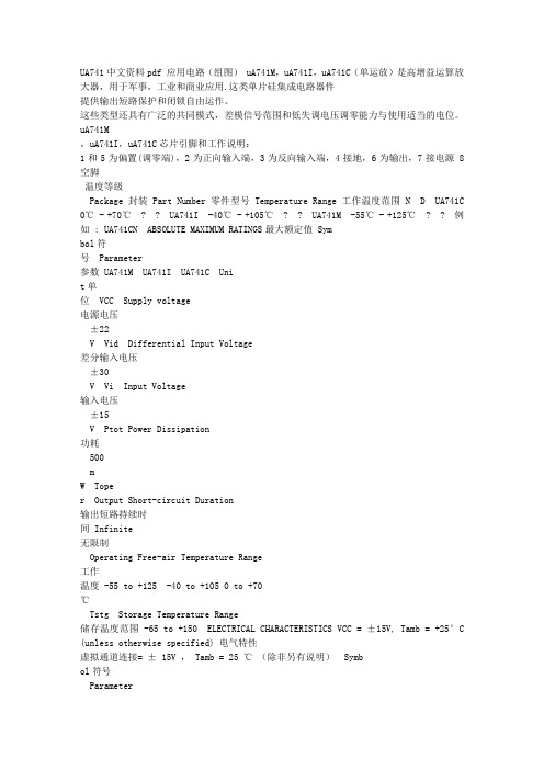
Micro-D PCB - .050" Contact SpacingMDM-PCBHow to Order - MDM-PCB Series
18www.ittcannon.comDimensions shown in inch (mm)Specifications and dimensions subject to change
MDM-PCB connectors are designed for usewith flex circuitry, flat cable and printed circuitboards or multi-layer boards. They use thestandard MDM metal shell and provide highdensity and high reliability in board-to-board,board-to-cable and cable-to-cable applications.
MDM-PCB connectors are available in 8 shellsizes with 9 to 100 contacts. Terminationsmay be straight (BS) or at 90˚ right angle (BR,CBR) board thickness. Jackpost mounting foruse with locking hardware is also available.
SERIES INSULATOR MATERIAL CONTACTARRANGEMENT CONTACTTYPE TERMINATION TYPE MOUNTING HARDWARE (Shell Flange) MOUNTING HARDWARE FOR PCB TERMINATION TAIL LENGTH MODIFICATION CODE SHELL FINISH MODIFICATION CODES SERIES
MOUNTING HARDWARE FOR PCBTERMINATION TAIL LENGTH MODIFICATION CODE
SHELL FINISH MODIFICATION CODESINSULATOR MATERIALCONTACTARRANGEMENTCONTACTTYPE
TERMINATION TYPEMOUNTING HARDWARE (Shell Flange)MDM - Micro "D" Metal Shell
T-Threaded Insert #2-56 Thd for Shell Sizes 9 thru 51 #4-40 Thd for Shell Size 100No letter - none
None - .109 (2.77) ±.015 (0.38) StandardL61 - .125 (3.18)L56 - .150 (3.81)L57 - .190 (4.83)L39 - .250 (6.35)L58 - .375 (9.52)
None - Yellow Chromate/Cadmium over NickelA174 - Electroless NickelA172 - Gold over NickelA141 - Irridite/AlodineA30 - Black Anodize
(For special modification codes, consult customer service.)NOTE: Back molding material –
Epoxy Hysol #MG40FS
MDM * - - 25PPBSTL39 A174 Liquid Crystal Polymer (LCP)9, 15, 21, 25, 31, 37, 51, and 100
P-Pin (Plug)S-Socket (Receptacle)
BS - Straight PCB TerminationBR - Right Angle PCB TerminationCBR - Right Angle Narrow Profile PCB Terminations
P-JackpostsM7 - Jackposts M83513/5-07 (Sizes 9-51)M17 - JackpostsM83513/5-17 (Size 100)No letter - none
RoHS COMPLIANCER元器件交易网www.cecb2b.comMicro-D PCB - .050" Contact SpacingMDM-PCBBS (Board Straight) Series
19www.ittcannon.com*.096 ± .005(2.44 ± 0.13) DIA.Size 9-51)
.120 ± .005(3.05 ± 0.13)Size 100
CAV.#1LAST
CAV.
G
JACKPOST(9-51)#2-56 UNC-2B TYP.
JACKPOST(100)#4-40 UNC-2B TYP.
.186 (4.72) MAX. PLUG.198 (5.03) MAX. RECEPTACLE
.109 ± 0.15(2.77 ± 0.38)
DE
HJK
LASTCAV.CAV. #1.050(1.27)678912345910 11 12 13 14 151234567812 13 14 15 16 17 18 19 20 21123456789101114 15 16 17 18 19 20 21 22 23 24 251234567891011 12 1317 18 19 20 21 22 23 24 25 26 27 28 29 30 311234567891011 12 13 14 15 1620 21 22 23 24 25 26 27 28 29 30 31 32 33 34 35 36 371234567891011 12 13 14 15 16 17 18 1936 37 38 39 40 41 42 43 44 45 46 47 48 49 50 5119351234567891011 12 13 14 15 16 17 181234567891011 12 13 14 15 16 17 18 19 20 21 22 23 24 25 267677 78 79 80 81 82 83 84 85 86 87 88 89 90 91 92 93 94 95 96 97 98 99 100 52 53 54 55 56 57 58 59 60 61 62 63 64 65 66 67 68 69 70 71 72 73 74 75 27 28 29 30 31 32 33 34 35 36 37 38 39 40 41 42 43 44 45 46 47 48 49 50 51.050(1.27).050(1.27).100(2.54)TYP..150(3.81).150(3.81).150(3.81).150(3.81).150(3.81).050(1.27)
.050
(1.27)
.050
(1.27)
.150(3.81).375
(9.53).225
(5.72)TYP.
.225(5.72)
PCB Termination Arrangements* (Viewed from PCB solderside)
9Contacts31 Contacts15 Contacts37 Contacts100 Contacts51 Contacts21 Contacts25 ContactsIdentification number shown for plug connector, use reverse orderfor socket connector.NOTE: Standard lead termination is #24 AWG, solid copper, solder or tin dippedAll Termination Configurations .100 (2.54) x .100 (2.54) Grid Pattern, Offset .050 (1.27)NOTE: Dimensions shown are forreference only-consult factory for final design dimensions.
.100 (2.54)REF.
FABC
B±.007 (.18)*Forjackpost, add letter "P" or "M7" for sizes 9-51, "M17" for size 100.PartNumberBy Shell SizeAMax.C±.005 (.13)DMax.EMax.FMax.GMax.HMax.JMax.K
Max.MDM-9PBS*MDM-9SBS*MDM-15PBS*MDM-15SBS*MDM-21PBS*MDM-21SBS*MDM-25PBSMDM-25SBS*MDM-31PBS*MDM-31SBS*MDM-37PBS*MDM-37SBS*MDM-51PBS*MDM-51SBS*MDM-100PBS*MDM-100SBS*1.390 (35.31)1.390 (35.31)1.390 (35.31)1.390 (35.31)1.690 (43.93)1.690 (43.93)1.740 (44.20)1.740 (44.20)2.040 (51.82)2.040 (51.82)2.340 (59.44)2.340 (59.44)2.270 (67.66)2.270 (67.66)3.070 (77.98)3.070 (77.98)1.150 (29.21)1.150 (29.21)1.150 (29.21)1.150 (29.21)1.450 (36.83)1.450 (36.83)1.500 (38.10)1.500 (38.10)1.800 (45.72)1.800 (45.72)2.100 (53.34)2.100 (53.34)2.000 (50.80)2.000 (50.80)2.800 (71.12)2.800 (71.12).565 (14.35).565 (14.35).715 (18.16).715 (18.16).865 (21.97).865 (21.97).965 (24.51).965 (24.51)1.115 (28.32)1.115 (28.32)1.265 (32.13)1.265 (32.13)1.215 (30.86)1.215 (30.86)1.800 (45.72)1.800 (45.72).785 (19.94).785 (19.94).935 (23.75).935 (23.75)1.085 (27.56)1.085 (27.56)1.185 (30.10)1.185 (30.10)1.335 (33.91)1.335 (33.91)1.485 (37.72)1.485 (37.72)1.435 (36.45)1.435 (36.45)2.175 (55.24)2.175 (55.24).334 (8.48).402 (10.21).484 (12.29).552 (13.97).634 (16.10).702 (17.83).734 (18.64).802 (20.37).884 (22.45).952 (24.18)1.034 (26.26)1.102 (27.99).984 (24.99)1.052 (26.72)1.384 (35.15)1.508 (38.30).185 (4.70).253 (6.43).185 (4.70).253 (6.43).185 (4.70).253 (6.43).185 (4.70).253 (6.43).185 (4.70).253 (6.43).185 (4.70).253 (6.43).228 (5.79).296 (7.52).271 (6.88).394 (10.01).308 (7.82).308 (7.82).308 (7.82).308 (7.82).308 (7.82).308 (7.82).308 (7.82).308 (7.82).308 (7.82).308 (7.82).308 (7.82).308 (7.82).351 (8.92).351 (8.92).460 (11.68).460 (11.68)