DL-5525-1625-SS中文资料
配线产品介绍 (中文)

配线产品系列中心机房子系统1.GPXKA-Z 型光纤总配架医用在新建机房独立光纤跳接场,现有机房独立光纤跳接场。
产品采用传统MDF 式的线缆管理方式、即直列模块部分为外线侧,提供室外光缆固定、汇流、熔接、与终端功能,横列模块部分为内线侧,提供室内光缆的终端、调度与管理功能。
采用前后双面操作,敞开式结构,上下均可进缆线。
尺寸外线侧内线侧总容量直列单元72芯托盘数量最大芯数横列单元96芯最大芯数2000*720*600954648657612242000*720*6001060720767213922000*720*6001272864876816322.GPXKA-T型光纤熔配为中心局机房,接入局点机房等需要在一个架体内进行分光、熔纤、配纤等工作的场景;采用正面操作,全/半封闭结构,上下均可进缆。
3.ZHGK型综合柜19和21英寸标准安装机柜,提供机房中的各种通信设备提供可靠地安装和保护的设备。
4.接续单元箱应用环境:19英寸安装,适用于综合柜和GPXKA-Ta型光纤熔配架。
5.电源分配单元适用于综合柜,提供引入电源的连接、分配和保护6.音频部件应用环境:适用于综合柜,提供引入电源的连接、分配和保护。
名称型号尺寸容量备注音频部件JPXK-A100H90*W260*D482内线128外线100选配告警单元,保安单元等音频部件JPXK-A100H90*W400*D482内线192外线200音频部件JPXK-A100H90*533*D482内线256外线300音频部件JPXK-A100H90*W711*D482内线384外线400音频部件JPXK-A100H90*W1020*D482内线512外线6007.数字单元体应用环境:西门子或NEC 制式,19英寸安装,适用于综合柜,提供同轴电缆的成端和调度。
馈线光缆子系统1.传统型光缆交接箱光缆交接箱(传统型)应用环境:为光传输网络、光接入网需要实现光缆、光纤的连接与调度的场景,实现短接主干光缆与配线光缆、并可放置光分路器的功能,箱体材质为不锈钢或SMC型。
2012勤上光电LED灯具选型样本
办公照明
P42-50
灯盘
P43-46
CR 线形灯组
P47-49
导光板灯盘 300×1200
CR1A 简明灯组
导光板灯盘 600×600
直下式灯盘 300×1200
直下式灯盘 600×600
CR1C 灯盘
CR9C 上下照灯组
LW 线形洗墙灯
P50
LW1B 洗墙灯
家居照明
P51-56
WM 室内壁灯
P52-P55
光源类
60 115 单位:mm
订购代码
标称功率
光通量
色温
显色指数
灯罩材质
灯头
SA19030830D08
3W
160lm
暖白
80
PC
E27
SA19030840D08
3W
175lm
正白
80
PC
E27
SA19030850D08
3W
190lm
冷白
75
PC
E27
SA19050830D08
5W
270lm
暖白
80
PC
散热能力卓越。 ● 采用最新的 LED 技术,保证持续的光输出和稳定的
颜色表现。
CRYSTAL 明晶系列 MR 灯
11
50
47
单位:mm 5.3
订购代码 SM16030330S01 SM16030330S02 SM16030340S01 SM16030340S02 SM16030350S01 SM16030350S02
显色指数 80 80 75 80 70 70 80 80 75 80 70 70
光源类
灯罩材质 乳白玻璃 乳白玻璃 乳白玻璃 乳白玻璃 乳白玻璃 乳白玻璃 乳白玻璃 乳白玻璃 乳白玻璃 乳白玻璃 乳白玻璃 乳白玻璃
索宝金属缠绕垫上型号说明
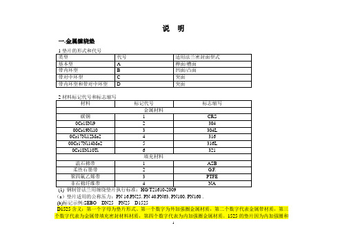
说明一.金属缠绕垫(a)垫片适用的公称压力:PN 16.PN25. PN 40.PN63. PN100. PN160 .(b)标记示例:SEBO DN25 PN25 D1525D1525含义:第一个字母为垫片形式、第一个数字为外加强圈金属材质,第二个数字代表金属带材质,第三个数字代表为金属带填充密封材料材质,第四个数字代表为内加强圈金属材质。
1525的垫片因为内加强圈和金属带使用了316L不锈钢,所以可以用在全站任意高腐蚀部位。
(2) 钢制管法兰用缠绕垫片执行标准:HG/T21631-2009(a)垫片适用的公称压力:Class150(PN 20.). Class300(PN 50.). Class600(PN 110.). Class900(PN 150.). Class1500(PN 260.). Class2500(PN 420.).(b)标记示例. 公称尺寸为DN100.公称压力为Class900的钢制管法兰用带内环和对中环的缠绕垫片(D型),对中环材料为碳钢,金属带材料为0Cr18Ni9,填充材料为柔性石墨带,内环材料为0Cr18Ni9,其标记为:缠绕垫SEBO MT600D 100- 900 1222二.八角垫2、执行标准(1) 钢制管法兰用金属环形垫执行标准:HG/T20612-2009(a)金属环形垫适用的法兰公称压力为:PN63、PN100、PN160(b)标记示例公称尺寸为DN100.公称压力为PN63的钢制管法兰用金属环形垫(八角形)材料为0Cr18Ni9其标记为:八角垫SEBO M6213 100-63 304(2)法兰用金属环形垫执行标准:HG/T20633-2009(a)金属环形垫适用的法兰公称压力为:Class150(PN 20.). Class300(PN 50.). Class600(PN 110.). Class900(PN 150.). Class1500(PN 260.). Class2500(PN 420.)(b)标记示例公称尺寸为DN100.公称压力为Class900的钢制管法兰用金属环形垫(八角形)材料为0Cr18Ni9其标记为:八角垫SEBO M6213 100-900 304三. 非石棉垫(1)钢制管法兰用非金属平垫:执行标准HG/T20606-2009公称尺寸为DN100.公称压力为PN63的突面法兰,选用非石棉垫片的标记为:非石棉垫SEBO G4500 100-63 RF(2)制管法兰用非金属平垫:执行标准HG/T20627-2009公称尺寸为DN100.公称压力为Class300的突面法兰,选用非石棉垫片的标记为:非石棉垫SEBO G4500 100-300 RF。
SONY APS-285型电源二合一板维修图解
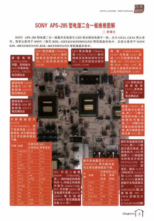
APPL-IATSICE : TREPA ITRIJSIGSONY APS -285型电源二合一板维修图解□景曙光SONY APS -285型电源二合一板集开关电源与L E D 背光驱动电路于一体,分为GE 2A 、GE 3A 两大系列,前者主要用于SONY (索尼)KDL -32EX 421/423/520/521/523等型液晶彩电中,后者主要用于SONY KDL -40EX 520/521/S 23、KDL -46EX 520/521/523 等型液晶彩电中。
PFC C6602、C6606并联,其两端为LEI)灯条供电-O UTU -OUT 3电压测试点LED 背光插座CN 6602,其-OUT 1、-〇UT 3 端对地电压在待机时均为 ()V ,二次开机后均为 113.8VL E D 背光插座C N 6601, 其 +O U T 1、+O U T 3 端对地电压在待机时均匀为 0V ,二次开机后分别为114.9Vdl5.4V电容 C 6604、C 6405、 C 6407与电感L 6401组 成+12V FI 型滤波电路, 输出 AU -12V 、REG 12V 和 B D R -ASU -12V ,实 测这几组电压在待机与 二次开机后均为12.46V滤流电容C 66W 两端为LEI )灯 条供电+OUT 3 电压测试点滤流电容C6611 两端为L E D 灯 i 条供电+O U T 1 电压测试点半桥驱动芯片IC 6702(CXD 9969AP ),用 于逆变形成LED 灯 条供电,其引脚功能 与正常在路电阻如 下表:|引脚|功能I C T—R T G N D P R O T SS ____VC1O C P V C 2P G N D V G L N C V B VS V G H在路电阻〇<0>红笔接地I 黑笔接地21.85.86010.23314.812.812.807414.23010.11467.50.0080.008007.8()1.17.8000C 0C 7.21000 6.8100015.2副开关电源芯片IC 6301 (MIP 2H 2),其引脚功能 与正常在路电阻如下表:1D 6508(F5K60M),其+、-端对地反向电阻脚功能红笔接地黑笔接地均为对地正向电阻1V D D 1807.52FB80010.8B P F C 开关管Q 65U 2及■3O L P 3010.8主电源开关管Q 6503、*14V C C 00 6.8Q 65I I 4等大功率|5D R A I N 1(K )07.6M C )S 「H T 管实测数据|6N C 30X见表2(4丨页)7.8S O U R C E13V 待机电压滤流电容 C 6211,其两端 为 S T B Y 33V 电压测试点插座CN 6201,通_过排线与主板相 连,其①…⑧脚为 控制信号输入或 检测信号输出 端,⑨w ⑯脚为电 压输出端或接地 端,各引脚具体功 能见表1(41页)副开关电源变压器T63U1,其①—③绕 组为高压绕组,直 流电阻为12U ;热 地侧⑤-⑥绕组输 出的电压分别经 D 6309X 6308 和D 6310、C 6307 滤波后,输出1625 V (待机时为16.MV) 和14.49V {待机时 为15.19V ),前者供给副开关电源源芯 片 丨C6301(M11J 2H 2)@®,S 者供给PFC: + P W M 控制芯片 IC6501(CXA 3S 01M K r a ®lPFC+PWM控制芯片I C6501 (CXA3801M),其⑲脚 ivCC)为15V供电端,其引脚功能与正常在 路电阻如下表:上屏电压控制管、C)(.4〇2(KJJ(l3iy),单P沟i i场效应 管,导通后输出T-CON-VCC- 12V电压,其引脚 功能与正常在路 电阻如右表:51脚功能接地mm接地1PFC-O U T111.2 2.6 2M O D E122012.1 3A C-D E T IN33 3.1 4A C-V R M S28011.2 5P F C-Z C D307.8 6PFC-SS0.20.2 7PF C-V A O827.8 PFC-VSEN SE288.2 9PFC-O V1)288.2 10P F C-T O N M A X557.8 11R M-O FFA H J808.2 12R M-FM1N1228.2 13R M-S S728.1 14K M-CS20.30.3 15R M-C S1U.30.3 16R M-R T1408.2 17VREF807.8 18G N D0019VCC56 6.8 20B-O K20013.2 21R M-O U T N11211.2 22A C-D E T O U T6012.8 23R M-O U T P11211.2 24M O D E220011.8I----1引脚丨功能I茬詒电Ii接地ffi(kQ) I黑笔接地卜3s极,+I2V输入 5.2 1.14C;极,接三极管IQ M013.20.95-8|丨)极,上屏电压输丨出".20.2•、松w,•^':Z71-3n•:i[5丨:丨.Atl,••1lUi»-/1!4i:“V“““,W•,’主开关电源变压器T6502,其次级⑧-⑭绕组与⑩-⑫绕组并绕,形成+ 12电压‘n丨背光供电变压器T6701,其次.级I K2绕组与®K5绕组串联,*形成+O U T1、+OUT3电压,4⑫-d i绕组形=成-OUTI、疆-O U T.、电压•.i m1•,%»*9J,I',淳须说明的是,采用该型二合一板的 液晶电视,在初次上电或在开机状 态下按机身电源键关机后,面板指 示灯不亮,此时仅副开关电源工 作,通过插座CN62I I I⑩脚输出 3.3V电压;上电后按一下机身电源 键或遥控待机时,CN6201①、③脚 电平跳变,P F C:电路与主开关电源 启动工作,PFC电压升至390V,并 从CN62U1⑫、利、⑯、⑯、⑳、⑩脚 输出+ 12V电压,此时面板红灯亮;二次开机后,CNf>2U丨⑤、®脚电平 跳变,背光电路启动,并从 C:N62(I1⑭、㉖、如脚输出12V上屏 电压,此时面板绿灯亮iu,.全桥D65U Z对输入市电进行整流,所到脉动直流电压经电阻R6503 ^R6506(330k f l x4)和 R65C I8(27k〖2)分压、二极管1)65()4{稳压值 12V)稳.压后送给丨C6501{CXA38U1M}③W,进行市电检测。
2012培训教材-轻中卡操纵部分解析

3
2012年培训教材
2012年培训教材
轻卡变速器操纵部分大致相同(见图1),不同的地 方在于使用不同变速器时所用的软轴固定支架、软轴及挡 位标牌不同,见表1。
4
2012年培训教材
2012年培训教材
图1
5
2012年培训教材
变速器型号 HW20505TCL HW24505TCL 布置型式 变速器左操纵 变速器左操纵 变速器左操纵 HW25505TCL 变速器右操纵 软轴 选LG9704240010(2400) 手柄 LG9704240026 LG9704240003 LG9704240003 LG9704240002 软轴支架 LG9704240032 LG9704240032 LG9704240011 LG9704240019
2012年培训教材
2012年培训教材
轻型卡车变速器操纵部分结构简介
技术中心 2012年2月
2012年培训教材
2012年培训教材
2012年培训教材
2012年培训教材
目前我公司轻卡系列车型变速器操纵采用双软轴操纵, 该结构布置方便,结构简单,便于模块化装配。 通过优化设计,合理布置软轴走向,支架结构简单,重 量轻。 挡位清晰,换选挡力度适中。
2012年培训教材
26
2012年培训教材
2012年培训教材
图7
27
2012年培训教材
(6)软轴及气管走向与固定
2012年培训教材
轻卡系列车型使用的软轴最小转弯半径为200mm,因此
在固定软轴时要避免软轴直径小于200mm。软轴使用扎带固 定,避免和其他运动部件磨碰、干涉,尽可能远离排气管。 装HW50508C变速器时气管顺着软轴进入驾驶室,和软轴捆绑 在一起。
钢丝绳芯输送带的分类及技术指标
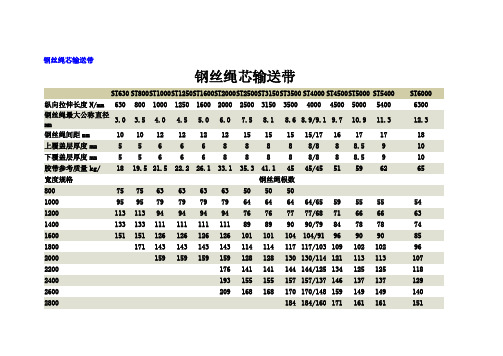
特点:拉伸强度大,抗冲击性好,寿命长,使用伸长率小,成槽性好,耐曲挠性好,适用于长距离,大运量、高速度物料输送。
用途:可广泛用于煤碳、矿山、港口、冶金、电力、化工等领域物料输送。
品种:按覆盖胶性能可分为:普通型、阻燃型、耐寒型、耐磨型、耐热型、耐酸碱型等品种。
按内部结构可分为:普通结构型、横向增强型、预埋线圈防撕裂型。
胶带质量根据覆盖胶厚度、密度变化说明:输送带单卷长度100-1500m, 受厚度、宽度、运输、安装等条件限制,每卷长度由供需双方确定。
电厂分散控制系统故障分析与处理作者:单位:摘要:归纳、分析了电厂DCS系统出现的故障原因,对故障处理的过程及注意事项进行了说明。
为提高分散控制系统可靠性,从管理角度提出了一些预防措施建议,供参考。
关键词:DCS故障统计分析预防措施随着机组增多、容量增加和老机组自动化化改造的完成,分散控制系统以其系统和网络结构的先进性、控制软件功能的灵活性、人机接口系统的直观性、工程设计和维护的方便性以及通讯系统的开放性等特点,在电力生产过程中得到了广泛应用,其功能在DAS、MCS、BMS、SCS、DEH系统成功应用的基础上,正逐步向MEH、BPC、ETS和ECS方向扩展。
但与此同时,分散控制系统对机组安全经济运行的影响也在逐渐增加;因此如何提高分散控制系统的可靠性和故障后迅速判断原因的能力,对机组的安全经济运行至关重要。
本文通过对浙江电网机组分散控制系统运行中发生的几个比较典型故障案例的分析处理,归纳出提高分散系统的可靠性的几点建议,供同行参考。
1考核故障统计浙江省电力行业所属机组,目前在线运行的分散控制系统,有TELEPERM-ME、MOD300,INFI-90,NETWORK-6000,MACSⅠ和MACS-Ⅱ,XDPS-400,A/I。
DEH有TOSAMAP-GS/C800,DEH-IIIA等系统。
笔者根据各电厂安全简报记载,将近几年因分散控制系统异常而引起的机组故障次数及定性统计于表1表1热工考核故障定性统计2热工考核故障原因分析与处理根据表1统计,结合笔者参加现场事故原因分析查找过程了解到的情况,下面将分散控制系统异常(浙江省电力行业范围内)而引起上述机组设备二类及以上故障中的典型案例分类浅析如下:2.1测量模件故障典型案例分析测量模件“异常”引起的机组跳炉、跳机故障占故障比例较高,但相对来讲故障原因的分析查找和处理比较容易,根据故障现象、故障首出信号和SOE记录,通过分析判断和试验,通常能较快的查出“异常”模件。
16215资料

PACIFIC DISPLAY DEVICESLCD Component Data SheetModel Number: 1621516 Character by 2 LineAlphanumeric LCD AssemblyWith COG ControllerNo internal backlight assemblyCONTENTSINFORMATION1. GENERALOverview 2 Product1.11.2 Part Numbering System 2Ratings 3 MaximumAbsolute1.31.4 Circuit Block Diagram 3Characteristics 3 Mechanical1.51.6 Input Signal Function 41.7 LCM Contrast Control and Bias 4Dimensions 5 LCD1.82. ELECTRICAL / OPTICAL CHARACTERISTICS2.1 DC Electrical Characteristics 62.2 AC Electrical Characteristics 6Characteristics 8 2.3Optical3. OPERATING PRINCIPALS AND METHODS3.1 LCD Controller Display and Control Functions 94. RELIABILITY 105. PRECAUTIONS FOR USING LCD MODULES 11139 Avenida Victoria – Suite 100 – San Clemente, CA – 92672Tel: 949-361-8957 – Fax: 949-361-9158 – Web: SPECIFICATIONS FOR LIQUID CRYSTAL DISPLAY MODULE MODEL NO: 16215 1. GENERAL INFORMATION1.1 Product Overview•16 Character x 2 line Alphanumeric Dot Matrix LCD Module•5V Operation•LCD Controller: Chip on Glass (COG) NT7603 or equivalent alpha-numeric controller• 4 Bit and 8 Bit parallel data interface options•Multiplexing driving: 1/16 duty, 1/4 bias•Operating Mode: TN (Twisted Nematic) or Super Twisted Nematic (STN) technology•LCD Module Service Life: 100,000 hours minimum1.2 Part Numbering System16215-SL-R-ST-12¾•¾••••¾•••¾••¾•(-6) 6 o’clock•(-12) 12 0’clockSPECIFICATIONS FOR LIQUID CRYSTAL DISPLAY MODULE MODEL NO: 162151.3 Absolute Maximum RatingsSupply voltage for logic V DD Supply voltage for LCD V DD – V0 -- V DD +0.3V Input voltage VI -0.3 V DD +0.3 V Standard Operating temperature TOP (-ST) 0 50 ºC Standard Storage temperature TST (-ST) -10 60 ºC Extended Operating temperature TOP (-ET) -20 70 ºC Extended Storage temperature TST (-ET) -30 80 ºC Soldering Temp Tsolder 260 ºC1.4 Circuit Block Diagram ~1.5 Mechanical CharacteristicsItem Contents UnitModule size (W ×H ×T)65 x 27.70 x 2.85 Max mm Viewing area (W ×H) 61.0 × 15.7mm Character matrix (W ×H) 5 × 8dots Character size (W ×H) 2.95 × 5.15mm Dot size (W ×H) 0.55 × 0.60mm Dot pitch (W ×H) 0.60 × 0.65mmSPECIFICATIONS FOR LIQUID CRYSTAL DISPLAY MODULE MODEL NO: 16215 1.6 Input Signal FunctionPin NO. Symbol Level Description1 VSS 0V Ground2 VO --- Bias voltage for LCD (Contrast)3 VDD 5.0V Supply voltage for logic4 RS H/L H : Data signal, L : Instruction signal5 R/W H/L H : Read mode, L : Write modeH,H6 E→ L Chip enable signal7 DB0 H/L Data bit 08 DB1 H/L Data bit 19 DB2 H/L Data bit 210 DB3 H/L Data bit 311 DB4 H/L Data bit 412 DB5 H/L Data bit 513 DB6 H/L Data bit 614 DB7 H/L Data bit 71.7 LCM Contrast Control and BiasSPECIFICATIONS FOR LIQUID CRYSTAL DISPLAY MODULE MODEL NO: 16215 1.8 LCM Dimensions (with Cable)SPECIFICATIONS FOR LIQUID CRYSTAL DISPLAY MODULE MODEL NO: 16215 1.8 LCM Dimensions (without Cable – Reference Only)SPECIFICATIONS FOR LIQUID CRYSTAL DISPLAY MODULE MODEL NO: 162152. ELECTRICAL / OPTICAL CHARACTERISTICS2.1 DC Electrical Characteristics (V DD = +5V ±10% , V SS = 0V, Ta = 25°C )Parameter Symbol Condition Min Typ Max UnitSupply voltage for logicV DD --- 4.5 5.0 5.5 V Supply current for logic I DD --- --- 1.0 1.5 mA 0°C --- --- --- V 25°C 0 --- V DD V Operating voltage for LCD V DD -V O 50°C --- --- --- V Input voltage ' H ' level V IH --- VDD - 2.2 --- VDD V Input voltage ' L ' levelV IL--- 0 --- 0.8 V2.2 AC Electrical Characteristics• Write ModeCharacteristic Symbol Min. Typ. Max. Unit Test pinE cycle time t C 500 --- --- ns E E rise time t r --- --- 25 ns E E fall timet f --- --- 25 ns E E pulse width (High, Low)t W 300 --- --- ns E R/W and RS set-up time (8 Bit) t SU160 --- --- ns R/W, RS R/W and RS set-up time (4 Bit) t SU1100 --- --- ns R/W, RS R/W and RS hold time t h110 --- --- ns R/W, RS Data set-up time t SU2100 --- --- ns DB 0 ~ DB 7Data hold timet h210 --- --- ns DB 0 ~ DB 7SPECIFICATIONS FOR LIQUID CRYSTAL DISPLAY MODULE MODEL NO: 16215 •Read ModepinMin. Typ. Max. Unit Test Characteristic SymbolE cycle time t C500 --- --- ns EE rise time t r--- --- 25 ns EE fall time t f--- --- 25 ns EE pulse width t W300 --- --- ns ER/W and RS set-up time (8 Bit) t SU60 --- --- ns R/W,RSRS R/W and RS set-up time (4 Bit) t SU100 --- --- ns R/W,RS R/W and RS hold time t h10 --- --- ns R/W,Data output delay time t D--- --- 190 ns DB0 ~ DB7Data hold time t DH20 --- --- ns DB0 ~ DB7SPECIFICATIONS FOR LIQUID CRYSTAL DISPLAY MODULE MODEL NO: 162152.3 Optical Characteristics (V OP = 4.7V, Ta = 25°C )Item Symbol Condition Min Typ Max Unit Remarks NoteResponse time Tr --- --- 180 --- ms --- 1Tf --- --- 98 --- ms --- 1 Contrast ratio Cr --- --- 7.5 --- --- --- 239 --- --- deg ∅ = 90° 3 35 --- --- deg ∅ = 270°3 37 --- --- deg ∅ = 0° 3 Viewing angle range θCr ≥ 2 36 --- --- deg ∅ = 180° 3SPECIFICATIONS FOR LIQUID CRYSTAL DISPLAY MODULE MODEL NO: 16215 3. OPERATING PRINCIPALS AND METHODES3.1 LCD Controller Display and Control FunctionsPlease refer to NOVATEK NT7603 DATASHEET.Pacific Display website: /ics_app%20notes/novatek/NT7603.pdfSPECIFICATIONS FOR LIQUID CRYSTAL DISPLAY MODULE MODEL NO: 16215 4. RELIABILITYLCD Panel Service LifeDefinition of panel service life•100,000 hours minimum at 25° C ±10%•Contrast becomes 30% of initial value•Current consumption becomes three times higher than initial value•Remarkable alignment deterioration occurs in LCD cell layer•Unusual operation occurs in display functionsSPECIFICATIONS FOR LIQUID CRYSTAL DISPLAY MODULE MODEL NO: 16215 5. PRECAUTIONS FOR USING LCD MODULESInstalling LCD ModulesThe hole in the printed circuit board is used to fix LCM as shown in the picture below. Attend to the following items when installing the LCM.1)Cover the surface with a transparent protective plate to protect the polarizer and LC cell.2)When assembling the LCM into other equipment, the spacer to the bit between the LCM and the fitting plateshould have enough height to avoid causing stress to the module surface, refer to the individual specifications formeasurements. The measurement tolerance should be ±0.1mm.Precaution for Handing LCD ModulesSince LCM has been assembled and adjusted with a high degree of precision, avoid applying excessive shocks to the module or making any alterations or modifications to it.1)Cover the surface with a transparent protective plate to protect the polarizer and LC cell.2)Do not alter, modify or change the shape of the tab on the metal frame.3)Do not make extra holes on the printed circuit board, modify its shape or change the positions of components tobe attached.4)Do not damage or modify the pattern writing on the printed circuit board.5)Absolutely do not modify the zebra rubber strip (conductive rubber) or heat seal connector.6)Except for soldering the interface, do not make any alterations or modifications with a soldering iron.7)Do not drop, bend or twist LCM.Electro-Static Discharge ControlSince this module uses a CMOS LSI, the same careful attention should be paid to electrostatic discharge as for an ordinary CMOS IC.1)Make certain that you are grounded when handing LCM.2)Before remove LCM from its packing case or incorporating it into a set, be sure the module and your body havethe same electric potential.3)When soldering the terminal of LCM, make certain the AC power source for the soldering iron does not leak.4)When using an electric screwdriver to attach LCM, the screwdriver should be of ground potentiality to minimizeas much as possible any transmission of electromagnetic waves produced sparks coming from the commutator ofthe motor.5)As far as possible make the electric potential of your work clothes and that of the work bench the groundpotential.6)To reduce the generation of static electricity be careful that the air in the work is not too dried. A relativehumidity of 50%-60% is recommended.Precaution for soldering to the LCM1)Observe the following when soldering lead wire, connector cable and etc. to the LCM.a)Soldering iron temperature : 280°C ± 10°C.b)Soldering time : 3-4 sec.2)Solder : eutectic solder.SPECIFICATIONS FOR LIQUID CRYSTAL DISPLAY MODULE MODEL NO: 162153)If soldering flux is used, be sure to remove any remaining flux after finishing to soldering operation. (This doesnot apply in the case of a non-halogen type of flux.) It is recommended that you protect the LCD surface with acover during soldering to prevent any damage due to flux spatters.4)When soldering the electroluminescent panel and PC board, the panel and board should not be detached morethan three times. This maximum number is determined by the temperature and time conditions mentioned above,though there may be some variance depending on the temperature of the soldering iron.5)When remove the electroluminescent panel from the PC board, be sure the solder has completely melted, thesoldered pad on the PC board could be damaged.Precautions for Operation1)Viewing angle varies with the change of liquid crystal driving voltage (VO). Adjust VO to show the best contrast.2)Driving the LCD in the voltage above the limit shortens its life.3)Response time is greatly delayed at temperature below the operating temperature range. However, this does notmean the LCD will be out of the order. It will recover when it returns to the specified temperature range.4)If the display area is pushed hard during operation, the display will become abnormal. However, it will return tonormal if it is turned off and then back on.5)Condensation on terminals can cause an electrochemical reaction disrupting the terminal circuit. Therefore, itmust be used under the relative condition of 40°C , 50% RH.6)When turning the power on, input each signal after the positive/negative voltage becomes stable.Safety•If the LCD panel breaks, be careful not to get the liquid crystal in your mouth. If the liquid crystal touches your skin or clothes, wash it off immediately using soap and plenty of water.Handling•The display panel is made of glass. Do not subject it to a mechanical shock by dropping it or impact.•If the display panel is damaged and the liquid crystal substance leaks out, be sure not to get any in your mouth. If the substance contacts your skin or clothes, wash it off using soap and water.•Do not apply excessive force to the display surface or the adjoining areas since this may cause the color tone to vary.•The polarizer covering the display surface of the LCD module is soft and easily scratched. Handle this polarizer carefully.•If the display surface becomes contaminated, breathe on the surface and gently wipe it with a soft dry cloth. If it is heavily contaminated, moisten cloth with one of the following solvents :o Isopropyl alcoholo Ethyl alcohol•Solvents other than those above-mentioned may damage the polarizer. Especially, do not use the following.o Watero Ketoneo Aromatic solvents•Exercise care to minimize corrosion of the electrode. Corrosion of the electrodes is accelerated by water droplets, moisture condensation or a current flow in a high-humidity environment.•Install the LCD Module by using the mounting holes. When mounting the LCD module make sure it is free of twisting, warping and distortion. In particular, do not forcibly pull or bend the I/O cable or the backlight cable.•Do not attempt to disassemble or process the LCD module.•NC terminal should be open. Do not connect anything.•If the logic circuit power is off, do not apply the input signals.SPECIFICATIONS FOR LIQUID CRYSTAL DISPLAY MODULE MODEL NO: 16215 •To prevent destruction of the elements by static electricity, be careful to maintain an optimum work environment.o Be sure to ground the body when handling the LCD modules.o Tools required for assembling, such as soldering irons, must be properly grounded.o To reduce the amount of static electricity generated, do not conduct assembling and other work under dry conditions.o The LCD module is coated with a film to protect the display surface. Exercise care when peeling off this protective film since static electricity may be generated.Storage•When storing the LCD modules, avoid exposure to direct sunlight or to the light of fluorescent lamps•Store the module in a dark place where the temperature is 25 o C ±10 o C and the humidity below 65% RH.•Do not store the module near organic solvents or corrosive gases.•Do not crush, shake, or jolt the module (including accessories).Cleaning•Do not wipe the polarizing plate with a dry cloth, as it may scratch the surface.•Wipe the module gently with soft cloth soaked with a petroleum benzene.•Do not use ketonic solvents (ketone and acetone) or aromatic solvents (toluene and xylene), as they may damage the polarizing plate.Others:•Liquid crystals solidify under low temperature (below the storage temperature range) leading to defective orientation or the generation of air bubbles (black or white). Air bubbles may also be generated if the module is subject to a low temperature.•If the LCD modules have been operating for a long time showing the same display patterns, the display patterns may remain on the screen as ghost images and a slight contrast irregularity may also appear. A normal operating status can be regained by suspending use for some time. It should be noted that this phenomenon does not adversely affect performance reliability.•To minimize the performance degradation of the LCD modules resulting from destruction caused by static electricity etc., exercise care to avoid holding the following sections when handling the modules.-Exposed area of the printed circuit board.-Terminal electrode sections.。
德力西电气产品选型手册2011版

A 一级配电A1 框架断路器01-5051-5556-6768-71A2 高压隔离开关A3高压熔断器A4三相干式变压器快速选型CDW6 框架断路器CDW1 框架断路器DW15 框架断路器DW17 框架断路器DW16 框架断路器3-78-2223-3637-4142-4748-5053-5354-5455-5558-5960-6061-6263-6465-6667-6770-7071-71快速选型GW9-12 单极隔离开关GN19-10 高压隔离开关快速选型XRNP1 高压限流熔断器RN 高压限流熔断器XRNT1 高压限流熔断器XRNM1 高压限流熔断器RW 高压跌落式熔断器快速选型SBK 三相干式变压器A1 框架断路器A 一级配电产品描述主要适用于配电网络中,用来分配电能,以及保护线路和设备免受过载、短路、接地等故障的危害,可避免不必要的停电,提高供电系统的可靠性、连续性和安全性符合标准国际标准 IEC 60947-1、IEC 60947-2、IEC 60947-4国家标准 GB/T 14048.1、GB 14048.2、GB 14048.4CDW6CDW1DW15DW17DW162A 1 框架断路器CDW6 框架断路器CDW6单选附件指南如果您需要更多扩展功能,可单独选购附件 (请参看附件编码订货)附件编码用于附加远程操作功能的附件CDW6DCP 直流电源模块 输入DC220/110V 输出DC28V 2000-6300AF CDW6R继电器模块 AC250V/DC38V 2000-6300AF该产品技术参数详见此样本第8-22页3A 1 框架断路器缆绳联锁CDW6FL2固定式缆绳联锁 (二台)CDW6FL3固定式缆绳联锁 (三台)CDW6DL2抽屉式缆绳联锁 (二台)CDW6DL3抽屉式缆绳联锁 (三台)杠杆联锁CDW6DG2杠杆联锁 (二台)CDW6DG3杠杆联锁 (三台)CDW1 框架断路器本体部分默认标准配置附件: 分励,欠压,合闸,电操,4开4闭辅助触头,门框(2500A 以上规格),相间隔板,辅助接线端子47回路,M 型脱扣器该产品技术参数详见此样本第23-36页4A 1 框架断路器CDW1附件配置附件名称表DW15 框架断路器本体部分默认标准配置附件: 线圈(分励、欠压、合闸),控制箱(630A ),电操,通用继电器(1600A 以上),一组3开3闭辅助触点,2500和5000壳架默认为6开6闭该产品技术参数详见此样本第37-41页5A 1 框架断路器附件配置附件配置6A 1 框架断路器DW16 框架断路器本体部分默认标准配置附件: 分励,欠压,电操,一组3开3闭辅助触点,杠杆操作手柄(630-2000A)该产品技术参数详见此样本第48-50页7A 1 框架断路器框架断路器CDW6壳架等级2000A 、3200A 、6300A 额定电流 In (A)630~6300额定电压 Ue (V)400极数 3极,4极安装方式固定式,抽屉式智能控制器L 型基本功能:保护功能 (L, S, I & G)M 型基本保护功能, 基本测量功能, 辅助功能H 型基本与高级保护功能, 多种测量功能, 辅助功能 &通讯功能远程操作分励脱扣器, 欠压脱扣器, 合闸电磁铁, 电动机操作机构 &辅助触头外接互感器N 相外接互感器, 接地互感器, 漏电互感器锁分闸锁, 门联锁连接绳索联锁, 杠杆联锁, 相间隔板控制单元附件交流电源模块, 直流电源模块, 继电器模块操作门框 , 透明防护罩附件技术参数8A 1 框架断路器额定运行短路分断能力Ics 5080100额定短时耐受电流Icw(1s)506585使用寿命机械寿命 有维护1000080005000机械寿命无维护250025002500电气寿命 有维护10001000800电气寿命 无维护500500500L型智能控制器A 1 框架断路器自诊断功能故障历史记录测试功能A 1 框架断路器动作电流Isd 0.4~15In+OFF 整定步长10kA 以下:≤2A, 10kA 以上≤10A 2Ig 0.2 1.0In+OFF动作时间tG0.1s, 0.2s, 0.3s, 0.4s, OFFH型智能控制器A 1 框架断路器动作电流I R OFF+0.4 1.0In 保护曲线SI: 标准反时限类型选择VI: 快速反时限EI(G): 特快反时限(配电)EI(M): 特快反时限(电动机)动作电流Ig OFF+0,2~1.0xIn 反时限剪切系数Cr 1.5~6, +OFF 延时时间tg0.1~1s分励线圈远程操作功能介绍在断路器储能后,能够在规定的电源电压下,通过远程遥控操作,使断路器断开A 1 框架断路器欠压线圈及欠压延时线圈合闸线圈电动机操作机构功能介绍在断路器储能并通电后,当断路器电压下降到70%-35%的额定电压时,能够动作,使断路器断开。
- 1、下载文档前请自行甄别文档内容的完整性,平台不提供额外的编辑、内容补充、找答案等附加服务。
- 2、"仅部分预览"的文档,不可在线预览部分如存在完整性等问题,可反馈申请退款(可完整预览的文档不适用该条件!)。
- 3、如文档侵犯您的权益,请联系客服反馈,我们会尽快为您处理(人工客服工作时间:9:00-18:30)。
1625 nm DFB LASER DIODE MODULES DL-5500S-1625 Series 2.5 Gbps UNCOOLED MQW DFB LD WITH RECEPTACLE
*******************************************************************************************************************************************************
FEATURES
² 1625 nm Uncooled Laser Diode with MQW Structure
² High Reliability, Long Operation Life
² Single Frequency Operation with High SMSR
² 0 to 70o C operation without active cooling
² Build-in InGaAs monitor
² Speed upto 2.5 Gbps
APPLICATION
Trunk Line, FitL
DESCRIPTION
DL-5500S-1625 series are designed for coupling a single mode optical fiber with 1625 nm MQW DFB uncooled laser diode. DL-5500S-1625 series are the best kits as light sources for telecom and datacom applications. ELECTRICAL AND OPTICAL CHARACTERISTICS (T C=25 °C)
Symbol Parameter Test Conditions Min. Typ. Max. Unit
I th Threshold Current CW 10 15 mA
V OP Operating V oltage CW, I F=Ith+25mA 1.2 1.5 V
P f Optical Output Power
Part No:DL-552XS-1625
DL-553XS-1625 CW, I F=Ith+25mA
1.0
2.0
-
-
-
-
-
mW
λc Center Wavelength CW, I th+25mA 1620 1625 1630 nm SMSR Side Mode Suppression Ratio CW, I th+25mA 30 35 dB
t r, t f Rise And Fall Times I F=I th, I th+25mA,20~80% 0.226 ns
ΔP f/ P f Tracking Error APC, 0~+70 ºC - - ±1.5 dB
I m PD Monitor Current CW, I th+25mA,V RD=1V 100 μA
I D PD Dark Current V RD=5V 0.1 μA
C t P
D Capacitance V RD=5V, f=1MHz 10 15 pF
ABSOLUTE MAXIMUM RATINGS (T C=25 ºC)
Symbol Parameter Ratings Unit
P o Optical Output Power (552XS/553XS) 1.5 / 3 mW
V RL LD Reverse V oltage 2 V
V RD PD Reverse V oltage 10 V
I FD PD Forward Current 1.0 mA
T opr Operating Temperature 0 to 70 ºC
T stg Storage Temperature -40~+85 ºC
*******************************************************************************************************************************************************
MECHANICAL DIMENSION (mm) and PIN ASSIGNMENT
Note: Specifications subject to change without notice.
ORDER INFORMATION
Part No.: D L − 5 5 □□
*******************************************************************************************************************************************************。