PCG1C471MCL1GS中文资料
宏碁 Aspire 4741G系列配置参数

1Aspire 4741G 系列配置参数酷睿i5系列5000元以内的:宏碁 Aspire 4741G-432G32Mn ¥4550∙ 笔记本屏幕:14英寸 ∙ CPU :Intel 酷睿i5 430M ∙ 主频:2.26GHz ∙ 内存:2GB ∙ 硬盘:320GB∙ 显卡:NVIDIA GeForce GT 3...宏碁 Aspire 4745G-432G32Mn-1 ¥4999∙ 笔记本屏幕:14英寸 ∙ CPU :Intel 酷睿i5 430M ∙ 主频:2.26GHz ∙ 内存:2GB ∙ 硬盘:320GB∙ 显卡:ATI Mobility Radeon...宏碁 Aspire 4741G-5462G32Mnck ¥4650∙ 笔记本屏幕:14英寸 ∙ CPU :Intel 酷睿i5 460M ∙ 主频:2.53GHz ∙ 内存:2GB ∙ 硬盘:320GB∙ 显卡:NVIDIA GeForce GT 4...宏碁 Aspire 4741G-5462G32MNKK ¥4700∙ 笔记本屏幕:14英寸 ∙ CPU :Intel 酷睿i5 460M ∙ 主频:2.53GHz ∙ 内存:2GB ∙ 硬盘:320GB∙ 显卡:NVIDIA GeForce GT 4...宏碁 Aspire 4741G-432G32Mn-2 ¥4600∙ 笔记本屏幕:14英寸 ∙ CPU :Intel 酷睿i5 430M ∙ 主频:2.26GHz ∙ 内存:2GB ∙ 硬盘:320GB∙ 显卡:NVIDIA GeForce GT 3...宏碁 Aspire 4741G-5462G32Mnrr ¥4799∙ 笔记本屏幕:14英寸 ∙ CPU :Intel 酷睿i5 460M ∙ 主频:2.53GHz ∙ 内存:2GB ∙ 硬盘:320GB∙ 显卡:NVIDIA GeForce GT 4...宏碁 Aspire 4741G-432G32Mnkk ¥4700∙ 笔记本屏幕:14英寸 ∙ CPU :Intel 酷睿i5 430M ∙ 主频:2.26GHz ∙ 内存:2GB ∙ 硬盘:320GB∙ 显卡:NVIDIA GeForce GT 4...宏碁 Aspire 4741G-452G32Mn 新品∙ 笔记本屏幕:14英寸 ∙ CPU :Intel 酷睿i5 450M ∙ 主频:2.4GHz ∙ 内存:2GB ∙ 硬盘:320GB∙ 显卡:NVIDIA GeForce GT 3...宏碁 Aspire 4740G-432G32Mn-2 ¥4800∙ 笔记本屏幕:14英寸 ∙ CPU :Intel 酷睿i5 430M ∙ 主频:2.26GHz ∙ 内存:2GB ∙ 硬盘:320GB∙ 显卡:NVIDIA GeForce 310M宏碁 Aspire 4740G-432G32Mn-1 ¥4990∙ 笔记本屏幕:14英寸 ∙ CPU :Intel 酷睿i5 430M ∙ 主频:2.26GHz ∙ 内存:2GB ∙ 硬盘:320GB∙显卡:NVIDIA GeForce 310M详细配置单:宏碁Aspire 4741G-332G32Mn-1 ¥3799 主要性能 产品定位 家用 处理器 Intel 酷睿i3 330M 处理器主频 2.13GHz 二级缓存 512KB 三级缓存 3MB 总线频率 DMI处理器描述 双核心四线程 主板芯片组 Intel HM55 内存容量 2GB内存类型 DDR3 1066 内存描述 2个内存插槽 最大内存容量 8GB 硬盘容量 320GB硬盘描述 SATA 接口, 5400转 光驱类型 DVD 刻录机光驱描述 内置托盘式, 支持双层刻录 显示屏 屏幕尺寸 14英寸 显示屏类型 普通宽屏 标准分辨率 1366×768 屏幕比例 16:9 背光技术 LED 背光视频 显卡类型 独立显卡显卡型号 NVIDIA GeForce 310M 显存容量 512MB 显存位宽 64位 流处理器个数 16 DirectX 10音频 扬声器 内置扬声器 麦克风 内置麦克风网络传输 无线上网 802.11b/g/n(300Mbps) 有线上网 千兆以太网卡主要接口 数据接口 3个USB2.0 视频接口 HDMI, VGA音频接口 音频输出, 麦克风输入 网络接口 RJ45网线接口 读卡器 5合1读卡器其它功能 指取设备 触摸板(带滚轮、多点触摸) 摄像头 内置130万摄像头宏碁Aspire 4741G-332G32Mn-2 ¥3999 主要性能 产品定位 家用 处理器 Intel 酷睿i3 330M 处理器主频 2.13GHz 二级缓存 512KB 三级缓存 3MB 总线频率 DMI处理器描述 双核心四线程 主板芯片组 Intel HM55 内存容量 2GB内存类型 DDR3 1066 内存描述 2个内存插槽 最大内存容量 8GB 硬盘容量 320GB硬盘描述 SATA 接口, 5400转 光驱类型 DVD 刻录机光驱描述 内置托盘式, 支持双层刻录 显示屏 屏幕尺寸 14英寸 显示屏类型 普通宽屏 标准分辨率 1366×768 屏幕比例 16:9 背光技术 LED 背光视频 显卡类型 独立显卡显卡型号 NVIDIA GeForce 310M 显存容量 1GB 显存位宽 64位流处理器个数 16 DirectX 10音频 扬声器 内置扬声器 麦克风 内置麦克风网络传输 无线上网 802.11b/g/n(300Mbps) 有线上网 千兆以太网卡主要接口 数据接口 3个USB2.0 视频接口 HDMI, VGA音频接口 音频输出, 麦克风输入 网络接口 RJ45网线接口 读卡器 5合1读卡器其它功能 指取设备 触摸板(带滚轮、多点触摸) 摄像头 内置130万摄像头宏碁Aspire 4741G-332G32Mn W7 ¥4250 主要性能 产品定位 家用 处理器 Intel 酷睿i3 330M 处理器主频 2.13GHz 二级缓存 512KB 三级缓存 3MB 总线频率 DMI处理器描述 双核心四线程 主板芯片组 Intel HM55 内存容量 2GB内存类型 DDR3 1066 内存描述 2个内存插槽 最大内存容量 8GB 硬盘容量 320GB硬盘描述 SATA 接口, 5400转 光驱类型 DVD 刻录机光驱描述 内置托盘式, 支持双层刻录 显示屏 屏幕尺寸 14英寸 显示屏类型 普通宽屏 标准分辨率 1366×768 屏幕比例 16:9 背光技术 LED 背光视频 显卡类型 独立显卡显卡型号 NVIDIA GeForce GT 330M 显存容量 1GB 显存位宽 128位 流处理器个数 48 DirectX 10.1音频 扬声器 内置扬声器 麦克风 内置麦克风网络传输 无线上网 802.11b/g/n(300Mbps) 有线上网 千兆以太网卡主要接口 数据接口 3个USB2.0 视频接口 HDMI, VGA音频接口 音频输出, 麦克风输入 网络接口 RJ45网线接口 读卡器 5合1读卡器其它功能 指取设备 触摸板(带滚轮、多点触摸) 摄像头 内置130万摄像头宏碁Aspire 4741G-332G32Mn ¥3999 主要性能 产品定位 家用 处理器 Intel 酷睿i3 330M 处理器主频 2.13GHz 二级缓存 512KB 三级缓存 3MB 总线频率 DMI处理器描述 双核心四线程 主板芯片组 Intel HM55 内存容量 2GB内存类型 DDR3 1066 内存描述 2个内存插槽 最大内存容量 8GB 硬盘容量 320GB硬盘描述 SATA 接口, 5400转 光驱类型 DVD 刻录机光驱描述 内置托盘式, 支持双层刻录 显示屏 屏幕尺寸 14英寸 显示屏类型 普通宽屏 标准分辨率 1366×768屏幕比例 16:9背光技术 LED背光视频显卡类型独立显卡显卡型号 NVIDIA GeForce GT 330M显存容量 1GB显存位宽 128位流处理器个数 48DirectX 10.1音频扬声器内置扬声器麦克风内置麦克风网络传输无线上网 802.11b/g/n(300Mbps)有线上网千兆以太网卡主要接口数据接口 3个USB2.0视频接口 HDMI, VGA音频接口音频输出, 麦克风输入网络接口 RJ45网线接口读卡器 5合1读卡器其它功能指取设备触摸板(带滚轮、多点触摸) 摄像头内置130万摄像头宏碁Aspire 4741G-332G50Mn ¥4000 [已停产]主要性能产品定位家用处理器 Intel 酷睿i3 330M处理器主频 2.13GHz二级缓存 512KB三级缓存 3MB总线频率 DMI处理器描述双核心四线程主板芯片组 Intel HM55内存容量 2GB内存类型 DDR3 1066内存描述 2个内存插槽最大内存容量 8GB硬盘容量 500GB硬盘描述 SATA接口, 5400转光驱类型 DVD刻录机光驱描述内置托盘式, 支持双层刻录显示屏屏幕尺寸 14英寸显示屏类型普通宽屏标准分辨率 1366×768屏幕比例 16:9背光技术 LED背光视频显卡类型独立显卡显卡型号 NVIDIA GeForce GT 330M显存容量 1GB显存位宽 128位流处理器个数 48DirectX 10.1音频扬声器立体声扬声器麦克风内置麦克风网络传输无线上网 802.11b/g/n(300Mbps)有线上网千兆以太网卡主要接口数据接口 3个USB2.0视频接口 HDMI, VGA音频接口音频输出, 麦克风输入网络接口 RJ45网线接口读卡器 5合1读卡器其它功能指取设备触摸板(带滚轮、多点触摸) 摄像头内置130万摄像头安全功能安全锁孔电能规格电池规格 6芯锂电池(4400mAh)续航时间约4小时, 具体时间视使用环境而定外观特征机身材质复合材料机身颜色蓝色顶盖, 黑色键盘长度 342毫米宽度 245毫米厚度 31.9毫米重量 2.2千克随机配件操作系统 Linux随机配件锂电池, 电源适配器, 说明书附带软件 Acer eRecovery Management等宏碁4741G-332G50Mn-2 ¥3999基本参数上市时间 2010年 4月处理器 Intel Core i3-330M(2.13GHz) 核心架构 Arrandale 32nm双核处理器类型酷睿i3处理器主频 2130MHzCPU内部缓存 L3 3M主板芯片组 Intel HM55系统总线 2.5 GT/S移动平台 Calpella平台产品定位家用,3D,轻便操作系统 DOS系统存储设备内存容量 2GB内存类型 DDR3硬盘类型 SATA硬盘硬盘参数 5400转硬盘容量 500GB光驱类型 DVD刻录机光驱描述支持SuperMulti双层刻录显示屏屏幕尺寸 14英寸显示屏描述宽屏,LED背光,16:9比例分辨率 1366×768音频视频显卡类型独立显卡芯片 nVidia Geforce 310M显存容量 512M显存位宽 64bit显存类型 DDR3流处理器数量 16显卡性能支持DirectX 10.1音频系统内置音效芯片扬声器内置扬声器通讯无线通讯 802.11b/g/n无线网卡网卡内置10-100-1000M网卡输入输出输入设备触摸板 USB 3个,USB2.0读卡器内置,五合一读卡器其它接口 VGA接口,RJ45,声音输入,声音输出孔,直流电源插孔,安全锁孔特色设备内置摄像头 130万像素摄像头结构特征重量约2.2Kg规格 342×245×25.5-31.9mm电能规格电池类型 6芯锂电池其它可选配件锂电池,电源适配器,软件光盘,说明书宏碁Aspire 4741G-352G32MN W7 ¥4450主要性能产品定位家用处理器 Intel 酷睿i3 350M处理器主频 2.26GHz二级缓存 512KB三级缓存 3MB总线频率 DMI处理器描述双核心四线程主板芯片组 Intel HM55内存容量 2GB内存类型 DDR3 1066内存描述 2个内存插槽最大内存容量 8GB硬盘容量 320GB硬盘描述 SATA接口, 5400转光驱类型 DVD刻录机光驱描述内置托盘式, 支持双层刻录显示屏屏幕尺寸 14英寸显示屏类型普通宽屏标准分辨率 1366×768屏幕比例 16:9背光技术 LED背光视频显卡类型独立显卡显卡型号 NVIDIA GeForce GT 320M显存容量 1GB显存位宽 128位流处理器个数 24DirectX 10.1音频扬声器内置扬声器麦克风内置麦克风网络传输无线上网 802.11b/g/n(300Mbps)有线上网千兆以太网卡主要接口数据接口 3个USB2.0视频接口 HDMI, VGA音频接口音频输出, 麦克风输入网络接口 RJ45网线接口读卡器 5合1读卡器其它功能指取设备触摸板(带滚轮、多点触摸)摄像头内置130万摄像头宏碁Aspire 4741G-352G32MN(GT330M独显)¥4500主要性能产品定位家用处理器 Intel 酷睿i3 350M处理器主频 2.26GHz二级缓存 512KB三级缓存 3MB总线频率 DMI处理器描述双核心四线程主板芯片组 Intel HM55内存容量 2GB内存类型 DDR3 1066内存描述 2个内存插槽最大内存容量 8GB硬盘容量 320GB硬盘描述 SATA接口, 5400转光驱类型 DVD刻录机光驱描述内置托盘式, 支持双层刻录显示屏屏幕尺寸 14英寸显示屏类型普通宽屏标准分辨率 1366×768屏幕比例 16:9背光技术 LED背光视频显卡类型独立显卡显卡型号 NVIDIA GeForce GT 330M显存容量 1GB显存位宽 128位流处理器个数 48DirectX 10.1音频扬声器内置扬声器麦克风内置麦克风网络传输无线上网 802.11b/g/n(300Mbps)有线上网千兆以太网卡主要接口数据接口 3个USB2.0视频接口 HDMI, VGA音频接口音频输出, 麦克风输入网络接口 RJ45网线接口读卡器 5合1读卡器其它功能指取设备触摸板(带滚轮、多点触摸)摄像头内置130万摄像头宏碁Aspire 4741G-352G32MNKK/CK ¥4399主要性能产品定位家用处理器 Intel 酷睿i3 350M处理器主频 2.26GHz二级缓存 512KB三级缓存 3MB总线频率 DMI处理器描述双核心四线程主板芯片组 Intel HM55内存容量 2GB内存类型 DDR3 1066内存描述 2个内存插槽最大内存容量 8GB硬盘容量 320GB硬盘描述 SATA接口, 5400转光驱类型 DVD刻录机光驱描述内置托盘式, 支持双层刻录显示屏屏幕尺寸 14英寸显示屏类型普通宽屏标准分辨率 1366×768屏幕比例 16:9背光技术 LED背光视频显卡类型独立显卡显卡型号 NVIDIA GeForce GT 320M显存容量 1GB显存位宽 128位流处理器个数 24DirectX 10.1音频扬声器内置扬声器麦克风内置麦克风网络传输无线上网 802.11b/g/n(300Mbps)2有线上网千兆以太网卡主要接口数据接口 3个USB2.0视频接口 HDMI, VGA音频接口音频输出, 麦克风输入网络接口 RJ45网线接口读卡器 5合1读卡器其它功能指取设备触摸板(带滚轮、多点触摸) 摄像头内置130万摄像头宏碁Aspire 4741G-352G50MN ¥5700主要性能产品定位家用处理器 Intel 酷睿i3 350M处理器主频 2.26GHz二级缓存 512KB三级缓存 3MB总线频率 DMI处理器描述双核心四线程主板芯片组 Intel HM55内存容量 2GB内存类型 DDR3 1066内存描述 2个内存插槽最大内存容量 8GB硬盘容量 500GB硬盘描述 SATA接口, 5400转光驱类型 DVD刻录机光驱描述内置托盘式, 支持双层刻录显示屏屏幕尺寸 14英寸显示屏类型普通宽屏标准分辨率 1366×768屏幕比例 16:9背光技术 LED背光视频显卡类型独立显卡显卡型号 NVIDIA GeForce 310M显存容量 512MB显存位宽 64位流处理器个数 16DirectX 10.1音频扬声器内置扬声器麦克风内置麦克风网络传输无线上网 802.11b/g/n(300Mbps)有线上网千兆以太网卡主要接口数据接口 3个USB2.0视频接口 HDMI, VGA音频接口音频输出, 麦克风输入网络接口 RJ45网线接口读卡器 5合1读卡器其它功能指取设备触摸板(带滚轮、多点触摸) 摄像头内置130万摄像头宏碁Aspire 4741G-372G32MNCK ¥4450主要性能产品定位家用处理器 Intel 酷睿i3 370M处理器主频 2.4GHz二级缓存 512KB三级缓存 3MB总线频率 DMI处理器描述双核心四线程主板芯片组 Intel HM55内存容量 2GB内存类型 DDR3 1066内存描述 2个内存插槽最大内存容量 8GB硬盘容量 320GB硬盘描述 SATA接口, 5400转光驱类型 DVD刻录机光驱描述内置托盘式, 支持双层刻录显示屏屏幕尺寸 14英寸显示屏类型普通宽屏标准分辨率 1366×768屏幕比例 16:9背光技术 LED背光视频显卡类型独立/集成显卡型号 NVIDIA GeForce GT 320M集成Intel HD Graphics显存容量 1GB显存位宽 128位流处理器个数 24 DirectX 10.1音频扬声器内置扬声器麦克风内置麦克风网络传输无线上网 802.11b/g/n(300Mbps)有线上网千兆以太网卡主要接口数据接口 3个USB2.0视频接口 HDMI, VGA音频接口音频输出, 麦克风输入网络接口 RJ45网线接口读卡器 5合1读卡器其它功能指取设备触摸板(带滚轮、多点触摸)摄像头内置130万摄像头宏碁Aspire 4741G-372G32MNKK-1 ¥4300主要性能产品定位家用处理器 Intel 酷睿i3 370M处理器主频 2.4GHz二级缓存 512KB三级缓存 3MB总线频率 DMI处理器描述双核心四线程主板芯片组 Intel HM55内存容量 2GB内存类型 DDR3 1066内存描述 2个内存插槽最大内存容量 8GB硬盘容量 320GB硬盘描述 SATA接口, 5400转光驱类型 DVD刻录机光驱描述内置托盘式, 支持双层刻录显示屏屏幕尺寸 14英寸显示屏类型普通宽屏标准分辨率 1366×768屏幕比例 16:9背光技术 LED背光视频显卡类型独立/集成显卡型号 NVIDIA GeForce GT 320M集成Intel HD Graphics显存容量 1GB显存位宽 128位流处理器个数 24DirectX 10.1音频扬声器内置扬声器麦克风内置麦克风网络传输无线上网 802.11b/g/n(300Mbps)有线上网千兆以太网卡主要接口数据接口 3个USB2.0视频接口 HDMI, VGA音频接口音频输出, 麦克风输入网络接口 RJ45网线接口读卡器 5合1读卡器其它功能指取设备触摸板(带滚轮、多点触摸)摄像头内置130万摄像头宏碁Aspire 4741G-372G32MNKK(GT415)¥4299主要性能产品定位家用处理器 Intel 酷睿i3 370M处理器主频 2.4GHz二级缓存 512KB三级缓存 3MB总线频率 DMI处理器描述双核心四线程主板芯片组 Intel HM55内存容量 2GB内存类型 DDR3 1066内存描述 2个内存插槽最大内存容量 8GB硬盘容量 320GB硬盘描述 SATA接口, 5400转光驱类型 DVD刻录机光驱描述内置托盘式, 支持双层刻录显示屏屏幕尺寸 14英寸显示屏类型普通宽屏标准分辨率 1366×768屏幕比例 16:9背光技术 LED背光视频显卡类型独立/集成显卡型号 NVIDIA GeForce GT 415M集成Intel HD Graphics显存容量 1GB显存位宽 128位流处理器个数 48DirectX 11音频扬声器内置扬声器麦克风内置麦克风网络传输无线上网 802.11b/g/n(300Mbps)有线上网千兆以太网卡主要接口数据接口 3个USB2.0视频接口 HDMI, VGA音频接口音频输出, 麦克风输入网络接口 RJ45网线接口读卡器 5合1读卡器其它功能指取设备触摸板(带滚轮、多点触摸)摄像头内置130万摄像头宏碁Aspire 4741G-372G32MNKK ¥4399主要性能产品定位家用处理器 Intel 酷睿i3 370M处理器主频 2.4GHz二级缓存 512KB三级缓存 3MB总线频率 DMI处理器描述双核心四线程主板芯片组 Intel HM55内存容量 2GB内存类型 DDR3 1066内存描述 2个内存插槽最大内存容量 8GB硬盘容量 320GB硬盘描述 SATA接口, 5400转光驱类型 DVD刻录机光驱描述内置托盘式, 支持双层刻录显示屏屏幕尺寸 14英寸显示屏类型普通宽屏标准分辨率 1366×768屏幕比例 16:9背光技术 LED背光视频显卡类型独立/集成显卡型号 NVIDIA GeForce GT 420M集成Intel HD Graphics显存容量 1GB音频扬声器内置扬声器麦克风内置麦克风网络传输无线上网 802.11b/g/n(300Mbps)有线上网千兆以太网卡主要接口数据接口 3个USB2.0视频接口 HDMI, VGA音频接口音频输出, 麦克风输入网络接口 RJ45网线接口读卡器 5合1读卡器其它功能指取设备触摸板(带滚轮、多点触摸)摄像头内置130万摄像头宏碁4741G-372G32Mnkk(GT415M) ¥4999基本参数上市时间 2010年 9月处理器 Intel Core i3-370M(2.4GHz)核心架构 Arrandale 32nm双核处理器类型酷睿i3处理器主频 2400MHzCPU内部缓存 L3 3M主板芯片组 Intel HM55系统总线 2.5 GT/S移动平台 Calpella平台产品定位家用,轻便,中低端操作系统 DOS系统存储设备内存容量 2GB内存类型 DDR3最大支持内存最大支持8GB硬盘类型 SATA硬盘硬盘参数 5400转硬盘容量 320GB光驱类型 DVD刻录机显示屏屏幕尺寸 14英寸3显示屏描述宽屏,LED背光,16:9比例分辨率 1366×768音频视频显卡类型独立显卡芯片 NVIDIA GeForce GT 415M显存容量 1024M显存位宽 128bit显存类型 DDR3流处理器数量 48显卡性能支持DirectX 11音频系统内置音效芯片扬声器内置扬声器通讯网卡内置10-100-1000M网卡输入输出输入设备触摸板USB 3个,USB2.0读卡器五合一读卡器其它接口 VGA接口,HDMI接口,RJ45,声音输入,声音输出孔,直流电源插孔,安全锁孔特色设备内置摄像头内置摄像头指纹识别器无指纹识别器结构特征重量约2.2Kg规格 342×245×25.5-31.9mm电能规格电池类型 6芯锂电池其它可选配件锂电池,电源适配器,软件光盘,说明书宏碁Aspire 4741G-382G50MNKK 新品主要性能产品定位家用处理器 Intel 酷睿i3 380M处理器主频 2.53GHz二级缓存 512KB三级缓存 3MB总线频率 DMI处理器描述双核心四线程主板芯片组 Intel HM55内存容量 2GB内存类型 DDR3 1066内存描述 2个内存插槽最大内存容量 8GB硬盘容量 500GB硬盘描述 SATA接口, 5400转光驱类型 DVD刻录机光驱描述内置托盘式, 支持双层刻录显示屏屏幕尺寸 14英寸显示屏类型普通宽屏标准分辨率 1366×768屏幕比例 16:9背光技术 LED背光视频显卡类型独立显卡显卡型号 NVIDIA GeForce GT 420M显存容量 1GB显存位宽 128位流处理器个数 96DirectX 11音频扬声器内置扬声器麦克风内置麦克风网络传输无线上网 802.11b/g/n(300Mbps)有线上网千兆以太网卡主要接口数据接口 3个USB2.0视频接口 HDMI, VGA音频接口音频输出, 麦克风输入网络接口 RJ45网线接口读卡器 5合1读卡器其它功能指取设备触摸板(带滚轮、多点触摸) 摄像头内置130万摄像头安全功能安全锁孔电能规格电池规格 6芯锂电池(4400mAh)续航时间约4小时, 具体时间视使用环境而定外观特征机身材质复合材料机身颜色黑色长度 342毫米宽度 245毫米厚度 31.9毫米重量 2.2千克随机配件操作系统 Windows 7 家庭普通版随机配件锂电池, 电源适配器, 说明书附带软件随机软件宏碁Aspire 4741G-431G32MNKK 新品主要性能产品定位家用处理器 Intel 酷睿i5 430M处理器主频 2.26GHz二级缓存 512KB三级缓存 3MB总线频率 DMI处理器描述双核心四线程, 可睿频加速至2.53GHz主板芯片组 Intel HM55内存容量 1GB内存类型 DDR3 1066内存描述 2个内存插槽最大内存容量 8GB硬盘容量 320GB硬盘描述 SATA接口, 5400转光驱类型 DVD刻录机光驱描述内置托盘式, 支持双层刻录显示屏屏幕尺寸 14英寸显示屏类型普通宽屏标准分辨率 1366×768屏幕比例 16:9背光技术 LED背光视频显卡类型独立显卡显卡型号 NVIDIA GeForce GT 420M显存容量 1GB显存位宽 128位流处理器个数 96DirectX 11音频扬声器内置扬声器麦克风内置麦克风网络传输无线上网 802.11b/g/n(300Mbps)有线上网千兆以太网卡主要接口数据接口 3个USB2.0视频接口 HDMI, VGA音频接口音频输出, 麦克风输入网络接口 RJ45网线接口读卡器 5合1读卡器其它功能指取设备触摸板(带滚轮、多点触摸)摄像头内置130万摄像头安全功能安全锁孔电能规格电池规格 6芯锂电池(4400mAh)续航时间约4小时, 具体时间视使用环境而定外观特征机身材质复合材料机身颜色黑色长度 342毫米宽度 245毫米厚度 31.9毫米重量 2.2千克随机配件操作系统 Linux随机配件锂电池, 电源适配器, 说明书附带软件 Acer eRecovery Management等宏碁Aspire 4741G-432G25Mnkk ¥4680主要性能产品定位家用处理器 Intel 酷睿i5 430M处理器主频 2.26GHz二级缓存 512KB三级缓存 3MB总线频率 DMI处理器描述双核心四线程, 可睿频加速至2.53GHz主板芯片组 Intel HM55内存容量 2GB内存类型 DDR3 1066内存描述 2个内存插槽最大内存容量 8GB硬盘容量 250GB硬盘描述 SATA接口, 5400转光驱类型 DVD刻录机光驱描述内置托盘式, 支持双层刻录显示屏屏幕尺寸 14英寸显示屏类型普通宽屏标准分辨率 1366×768屏幕比例 16:9背光技术 LED背光视频显卡类型独立/集成显卡型号 NVIDIA GeForce GT 415M集成Intel HD Graphics显存容量 1GB显存位宽 128位流处理器个数 48DirectX 11音频扬声器内置扬声器麦克风内置麦克风网络传输无线上网 802.11b/g/n(300Mbps)有线上网千兆以太网卡蓝牙支持主要接口数据接口 3个USB2.0视频接口 HDMI, VGA音频接口音频输出, 麦克风输入网络接口 RJ45网线接口读卡器 5合1读卡器其它功能指取设备触摸板(带滚轮、多点触摸)摄像头内置130万摄像头宏碁Aspire 4741G-432G32Mn-2 ¥4600主要性能产品定位家用处理器 Intel 酷睿i5 430M处理器主频 2.26GHz二级缓存 512KB三级缓存 3MB总线频率 DMI处理器描述双核心四线程, 可睿频加速至2.53GHz主板芯片组 Intel HM55内存容量 2GB内存类型 DDR3 1066内存描述 2个内存插槽最大内存容量 8GB硬盘容量 320GB硬盘描述 SATA接口, 5400转光驱类型 DVD刻录机光驱描述内置托盘式, 支持双层刻录显示屏屏幕尺寸 14英寸显示屏类型普通宽屏标准分辨率 1366×768屏幕比例 16:9背光技术 LED背光视频显卡类型独立显卡显卡型号 NVIDIA GeForce GT 330M显存容量 1GB显存位宽 128位流处理器个数 48DirectX 10.1音频扬声器内置扬声器麦克风内置麦克风网络传输无线上网 802.11b/g/n(300Mbps)有线上网千兆以太网卡主要接口数据接口 3个USB2.0视频接口 HDMI, VGA音频接口音频输出, 麦克风输入网络接口 RJ45网线接口读卡器 5合1读卡器其它功能指取设备触摸板(带滚轮、多点触摸)摄像头内置130万摄像头宏碁Aspire 4741G-432G32Mn ¥4550主要性能产品定位家用处理器 Intel 酷睿i5 430M处理器主频 2.26GHz二级缓存 512KB三级缓存 3MB总线频率 DMI处理器描述双核心四线程, 可睿频加速至2.53GHz主板芯片组 Intel HM55内存容量 2GB内存类型 DDR3 1066内存描述 2个内存插槽最大内存容量 8GB硬盘容量 320GB硬盘描述 SATA接口, 5400转光驱类型 DVD刻录机4光驱描述内置托盘式, 支持双层刻录显示屏屏幕尺寸 14英寸显示屏类型普通宽屏标准分辨率 1366×768屏幕比例 16:9背光技术 LED背光视频显卡类型独立显卡显卡型号 NVIDIA GeForce GT 330M显存容量 1GB显存位宽 128位流处理器个数 48DirectX 10.1音频扬声器内置扬声器麦克风内置麦克风网络传输无线上网 802.11b/g/n(300Mbps)有线上网千兆以太网卡主要接口数据接口 3个USB2.0视频接口 HDMI, VGA音频接口音频输出, 麦克风输入网络接口 RJ45网线接口读卡器 5合1读卡器其它功能指取设备触摸板(带滚轮、多点触摸) 摄像头内置130万摄像头宏碁Aspire 4741G-432G32Mnkk ¥4700主要性能产品定位家用处理器 Intel 酷睿i5 430M处理器主频 2.26GHz二级缓存 512KB三级缓存 3MB总线频率 DMI处理器描述双核心四线程, 可睿频加速至2.53GHz主板芯片组 Intel HM55内存容量 2GB内存类型 DDR3 1066内存描述 2个内存插槽最大内存容量 8GB硬盘容量 320GB硬盘描述 SATA接口, 5400转光驱类型 DVD刻录机光驱描述内置托盘式, 支持双层刻录显示屏屏幕尺寸 14英寸显示屏类型普通宽屏标准分辨率 1366×768屏幕比例 16:9背光技术 LED背光视频显卡类型独立显卡显卡型号 NVIDIA GeForce GT 420M显存容量 1GB显存位宽 128位流处理器个数 96DirectX 11音频扬声器内置扬声器麦克风内置麦克风网络传输无线上网 802.11b/g/n(300Mbps)有线上网千兆以太网卡主要接口数据接口 3个USB2.0视频接口 HDMI, VGA音频接口音频输出, 麦克风输入网络接口 RJ45网线接口读卡器 5合1读卡器其它功能指取设备触摸板(带滚轮、多点触摸) 摄像头内置130万摄像头宏碁Aspire 4741G-432G50Mn ¥4900主要性能产品定位家用处理器 Intel 酷睿i5 430M处理器主频 2.26GHz二级缓存 512KB三级缓存 3MB总线频率 DMI处理器描述双核心四线程, 可睿频加速至2.53GHz主板芯片组 Intel HM55内存容量 2GB内存类型 DDR3 1066 内存描述 2个内存插槽最大内存容量 8GB硬盘容量 500GB硬盘描述 SATA接口, 5400转光驱类型 DVD刻录机光驱描述内置托盘式, 支持双层刻录显示屏屏幕尺寸 14英寸显示屏类型普通宽屏标准分辨率 1366×768屏幕比例 16:9背光技术 LED背光视频显卡类型独立显卡显卡型号 NVIDIA GeForce GT 330M显存容量 1GB显存位宽 128位流处理器个数 48DirectX 10.1音频扬声器内置扬声器麦克风内置麦克风网络传输无线上网 802.11b/g/n(300Mbps)有线上网千兆以太网卡主要接口数据接口 3个USB2.0视频接口 HDMI, VGA音频接口音频输出, 麦克风输入网络接口 RJ45网线接口读卡器 5合1读卡器其它功能指取设备触摸板(带滚轮、多点触摸)摄像头内置130万摄像头宏碁Aspire 4741G-433G32Mn ¥4900主要性能产品定位家用处理器 Intel 酷睿i5 430M处理器主频 2.26GHz二级缓存 512KB三级缓存 3MB总线频率 DMI处理器描述双核心四线程, 可睿频加速至2.53GHz主板芯片组 Intel HM55内存容量 3GB内存类型 DDR3 1066内存描述 2个内存插槽最大内存容量 8GB硬盘容量 320GB硬盘描述 SATA接口, 5400转光驱类型 DVD刻录机光驱描述内置托盘式, 支持双层刻录显示屏屏幕尺寸 14英寸显示屏类型普通宽屏标准分辨率 1366×768屏幕比例 16:9背光技术 LED背光视频显卡类型独立显卡显卡型号 NVIDIA GeForce GT 330M显存容量 1GB显存位宽 128位流处理器个数 48DirectX 10.1音频扬声器内置扬声器麦克风内置麦克风网络传输无线上网 802.11b/g/n(300Mbps)有线上网千兆以太网卡蓝牙支持主要接口数据接口 3个USB2.0视频接口 HDMI, VGA音频接口音频输出, 麦克风输入网络接口 RJ45网线接口读卡器 5合1读卡器其它功能指取设备触摸板(带滚轮、多点触摸)摄像头内置130万摄像头宏碁Aspire 4741G-433G50MN ¥4880主要性能产品定位家用处理器 Intel 酷睿i5 430M处理器主频 2.26GHz二级缓存 512KB三级缓存 3MB总线频率 DMI处理器描述双核心四线程, 可睿频加速至2.53GHz主板芯片组 Intel HM55内存容量 3GB内存类型 DDR3 1066内存描述 2个内存插槽最大内存容量 8GB硬盘容量 500GB硬盘描述 SATA接口, 5400转光驱类型 DVD刻录机光驱描述内置托盘式, 支持双层刻录显示屏屏幕尺寸 14英寸显示屏类型普通宽屏标准分辨率 1366×768屏幕比例 16:9背光技术 LED背光视频显卡类型独立/集成显卡型号 NVIDIA GeForce GT 420M集成Intel HD Graphics显存容量 1GB显存位宽 128位流处理器个数 48DirectX 11音频扬声器内置扬声器麦克风内置麦克风网络传输无线上网 802.11b/g/n(300Mbps)有线上网千兆以太网卡主要接口数据接口 3个USB2.0视频接口 HDMI, VGA音频接口音频输出, 麦克风输入网络接口 RJ45网线接口读卡器 5合1读卡器其它功能指取设备触摸板(带滚轮、多点触摸)摄像头内置130万摄像头宏碁Aspire 4741G-452G32Mn 新品主要性能产品定位家用处理器 Intel 酷睿i5 450M处理器主频 2.4GHz二级缓存 512KB三级缓存 3MB总线频率 DMI处理器描述双核心四线程, 可睿频加速至2.66GHz主板芯片组 Intel HM55内存容量 2GB内存类型 DDR3 1066内存描述 2个内存插槽最大内存容量 8GB硬盘容量 320GB硬盘描述 SATA接口, 5400转光驱类型 DVD刻录机光驱描述内置托盘式, 支持双层刻录显示屏屏幕尺寸 14英寸显示屏类型普通宽屏标准分辨率 1366×768屏幕比例 16:9背光技术 LED背光视频显卡类型独立显卡显卡型号 NVIDIA GeForce GT 330M显存容量 1GB显存位宽 128位流处理器个数 48DirectX 10.1音频扬声器内置扬声器麦克风内置麦克风网络传输无线上网 802.11b/g/n(300Mbps)有线上网千兆以太网卡主要接口数据接口 3个USB2.0视频接口 HDMI, VGA音频接口音频输出, 麦克风输入网络接口 RJ45网线接口读卡器 5合1读卡器其它功能指取设备触摸板(带滚轮、多点触摸)摄像头内置130万摄像头5。
GMCC往复式压缩机产品手册说明书

RECIP COMPRESSOR 2020 Array往复式压缩机产品手册12144749我们的企业CompanyGREEN MILE 绿色里程1995年09月 公司成立Sep 1995, Company establishment 1996年10月X1C、X2C系列压缩机开始投产Oct 1996,X1C,X2C seriesrotary comp.2004年03月顺德容桂基地正式投产Mar 2004, Ronggui plant wentinto production2007年11月高效G1系列产品量产成功Nov 2007,High-efficiencyG1 series comp.2008年11月安徽合肥制冷基地投产2008年12月R410A冷媒双缸直流变频产品实现量产Dec 2008, R410A DCinverter twin cylinder comp.2000年10月交流变频机种研发成功实现量产Oct 2000, AC invertercomp.2003年09月R410A直流变频压缩机研发成功实现量产Sep 2003, R410A DCinverter comp.Nov 2008, Hefei plantwent into production2009年12月R134a热泵热水器专用压缩机投放市场Dec 2009, Special comp. forHP water heater in R134a2011年10月安徽芜湖空压基地投产Oct 2011, Wuhu plantwas put into production2011年11月2010年01月卧式系列冷冻压缩机研发成功,投入市场Jan 2010, Horizontalrefrigerating comp.2010年05月CO 热泵热水器专用压缩机研发成功May 2010, Comp. for HPwater heater in CO2010年06月第一亿台旋转式压缩机下线June 2010, The 100 millionthA/C compressor roll-out2010年10月双缸变容压缩机研发成功投入市场Oct 2010, Twin cylindervariable capacity comp.2012年07月2013年09月喷气增焓旋转式变频压缩机研发成功Sep 2013, Gas-injectioninverter comp.2013年09月第2亿台空调压缩机下线Sep 2013, The 200 millionthA/C compressor offline2014年全球市场占有率达30%In 2014, Market shareup to 30%2015年荣获2015年度广东省政府质量奖In 2015, Won theGuangdong QualityAward2016年11月独立压缩机研发成功并正式发布Nov 2016,I-CCC comp.2016年荣获2016年度安徽省质量奖In 2016, Won the AnhuiQuality Award2017年05月欧洲研发中心成立May 2017,EuropeanR&D centerestablishment签约为联合国蒙特利尔R290压缩机示范线Nov 2011, The UN MontrealR290 compressordemonstration line第3000万台变频压缩机下线July 2012,The 30 millionthDC inverter compressorroll-out2018年4月喷气变频热泵采暖专用压缩机正式发布Apr 2018,Heat pump heatingcomp. with EVI.2018年10月“V致能”小型变频空调压缩机研发成功并发布Oct 2018Miniaturized DCinverter comp.日本研发中心成立Japan R&D centerestablishment2019年第五亿台空调压缩机下线The 500 millionthA/C compressorroll-out0405在绿色节能大潮流下,冰箱压缩机行业呈现出高效化、小型化和节能化等技术发展趋势。
Micron 产品数据手册说明书
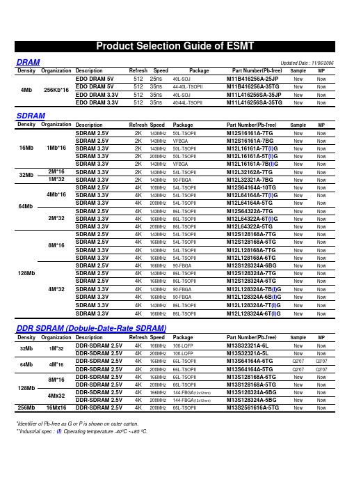
DRAMUpdated Date : 11/06/2006DensityOrganization DescriptionRefreshSpeedPackagePart Number(Pb-free)Sample MP EDO DRAM 5V 51225ns 40L-SOJ M11B416256A-25JP Now Now EDO DRAM 5V 51235ns 44-40L-TSOPII M11B416256A-35TG Now Now EDO DRAM 3.3V 51235ns 40L-SOJ M11L416256SA-35JP Now Now EDO DRAM 3.3V 51235ns 40/44L-TSOPIIM11L416256SA-35TGNowNowSDRAMDensityOrganization DescriptionRefresh SpeedPackagePart Number(Pb-free)Sample MP SDRAM 2.5V 2K 143MHz 50L-TSOPII M12S16161A-7TG Now Now SDRAM 2.5V 2K 143MHz VFBGA M12S16161A-7BG Now Now SDRAM 3.3V 2K 143MHz 50L-TSOPII M12L16161A-7T (I)G Now Now SDRAM 3.3V 2K 200MHz 50L-TSOPII M12L16161A-5T (I)G Now Now SDRAM 3.3V 2K 143MHz VFBGA M12L16161A-7B (I)G Now Now 2M*16SDRAM 3.3V 2K 143MHz 54L-TSOPII M12L32162A-7TG Now Now 1M*32SDRAM 3.3V 2K 143MHz 90-FBGA M12L32321A-7BG Now Now SDRAM 2.5V 4K 100MHz 54L-TSOPII M12S64164A-10TG Now Now SDRAM 3.3V 4K 143MHz 54L-TSOPII M12L64164A-7T (I)G Now Now SDRAM 3.3V 4K 200MHz 54L-TSOPII M12L64164A-5TG Now Now SDRAM 2.5V 4K 143MHz 86L-TSOPII M12S64322A-7TG Now Now SDRAM 3.3V 4K 166MHz 86L-TSOPII M12L64322A-6T (I)G Now Now SDRAM 3.3V 4K 200MHz 86L-TSOPII M12L64322A-5TG Now Now SDRAM 2.5V 4K 143MHz 54L-TSOPII M12S128168A-7TG Now Now SDRAM 2.5V 4K 166MHz 54L-TSOPII M12S128168A-6TG Now Now SDRAM 3.3V 4K 143MHz 54L-TSOPII M12L128168A-7TG Now Now SDRAM 3.3V 4K 166MHz 54L-TSOPII M12L128168A-6TG Now Now SDRAM 2.5V 4K 166MHz 90-FBGA M12S128324A-6BG Now Now SDRAM 2.5V 4K 143MHz 86L-TSOPII M12S128324A-7TG Now Now SDRAM 2.5V 4K 166MHz 86L-TSOPII M12S128324A-6TG Now Now SDRAM 3.3V 4K 143MHz 90-FBGA M12L128324A-7B (I)G Now Now SDRAM 3.3V 4K 166MHz 90-FBGA M12L128324A-6B (I)G Now Now SDRAM 3.3V 4K 143MHz 86L-TSOPII M12L128324A-7T (I)G Now Now SDRAM 3.3V4K166MHz86L-TSOPIIM12L128324A-6T (I)GNowNowDDR SDRAM (Dobule-Date-Rate SDRAM)Density Organization DescriptionRefresh SpeedPackagePart Number(Pb-free)Sample MP DDR-SDRAM 2.5V 4K 166MHz 100-LQFP M13S32321A-6L Now Now DDR-SDRAM 2.5V 4K 200MHz 100-LQFP M13S32321A-5L Now Now DDR-SDRAM 2.5V 4K 166MHz 66L-TSOPII M13S64164A-6TG Q2'07Q3'07DDR-SDRAM 2.5V 4K 200MHz 66L-TSOPII M13S64164A-5TG Q2'07Q3'07DDR-SDRAM 2.5V 4K 166MHz 66L-TSOPII M13S128168A-6TG Now Now DDR-SDRAM 2.5V 4K 200MHz 66L-TSOPII M13S128168A-5TG Now Now DDR-SDRAM 2.5V 4K 166MHz 144-FBGA (12x12mm)M13S128324A-6BG Now Now DDR-SDRAM 2.5V 4K 200MHz 144-FBGA (12x12mm)M13S128324A-5BG Now Now 256Mb16Mx16DDR-SDRAM 2.5V 4K200MHz66L-TSOPIIM13S2561616A-5TGNowNow*Identifier of Pb-free as G or P is shown on outer carton.**Industrial spec : (I) Operating temperature -40ºC ~+85 ºC.2M*3264Mb4Mb*1632Mb4Mb 256Kb*161Mb*1616Mb 128Mb8M*164Mx324M*32128Mb8M*1632Mb 64Mb1M*324M*16Mobile SDRAMDensityOrganizationDescriptionRefresh Speed Package & MCPPart Number(Pb-free)Sample MP Mobile SDRAM 2.5V4K 100MHz 50L-TSOPII M52S16161A-10T (I)G Now Now Mobile SDRAM 2.5V 4K 125MHz 50L-TSOPII M52S16161A-8T (I)G Now Now Mobile SDRAM 1.8V4K 100MHz50L-TSOPIIM52D16161A-10T (I)G Now Now Mobile SDRAM 2.5V 4K 100MHz 54L-TSOPII M52S32162A-10T (I)G Now Now Mobile SDRAM 2.5V 4K 100MHz 54-FBGA M52S32162A-10B (I)G Now Now Mobile SDRAM 2.5V 4K 133MHz 54L-TSOPII M52S32162A-7.5T (I)G Now Now Mobile SDRAM 2.5V 4K 133MHz 54-FBGA M52S32162A-7.5B (I)G Now Now Mobile SDRAM 1.8V 4K 100MHz 54L-TSOPII M52D32162A-10T (I)G Now Now Mobile SDRAM 1.8V 4K 100MHz 54-FBGA M52D32162A-10B (I)G Now Now Mobile SDRAM 1.8V 4K 100MHz 54L-TSOPII M52D32162A-7.5T (I)G Now Now Mobile SDRAM 1.8V 4K 133MHz 54-FBGA M52D32162A-7.5B (I)G Now Now Mobile SDRAM 2.5V 4K 100MHz 90-FBGA M52S32321A-10B (I)G Now Now Mobile SDRAM 2.5V 4K 133MHz 90-FBGA M52S32321A-7.5B (I)G Now Now Mobile SDRAM 1.8V 4K 100MHz 90-FBGA M52D32321A-10B (I)G Now Now Mobile SDRAM 1.8V 4K 133MHz 90-FBGA M52D32321A-7.5B (I)G Now Now Mobile SDRAM 2.5V 4K 100MHz 54L-TSOPII M52S64164A-10T (I)G Q2 '07Q3 '07Mobile SDRAM 2.5V 4K 100MHz 54-FBGA M52S64164A-10B (I)G Q2 '07Q3 '07Mobile SDRAM 2.5V 4K 133MHz 54L-TSOPII M52S64164A-7.5T (I)G Q2 '07Q3 '07Mobile SDRAM 2.5V 4K 133MHz 54-FBGA M52S64164A-7.5B (I)G Q2 '07Q3 '07Mobile SDRAM 1.8V 4K 100MHz 54L-TSOPII M52D64164A-10T (I)G Q2 '07Q3 '07Mobile SDRAM 1.8V 4K 100MHz 54-FBGA M52D64164A-10B (I)G Q2 '07Q3 '07Mobile SDRAM 1.8V 4K 100MHz 54L-TSOPII M52D64164A-7.5T (I)G Q2 '07Q3 '07Mobile SDRAM 1.8V 4K 133MHz 54-FBGA M52D64164A-7.5B (I)G Q2 '07Q3 '07Mobile SDRAM 2.5V 4K 100MHz 86L-TSOPII M52S64322A-10T (I)G Q2 '07Q3 '07Mobile SDRAM 2.5V 4K 100MHz 90-FBGA M52S64322A-10B (I)G Q2 '07Q3 '07Mobile SDRAM 2.5V 4K 133MHz 86L-TSOPII M52S64322A-7.5T (I)G Q2 '07Q3 '07Mobile SDRAM 2.5V 4K 133MHz 90-FBGA M52S64322A-7.5B (I)G Q2 '07Q3 '07Mobile SDRAM 1.8V 4K 100MHz 86L-TSOPII M52D64322A-10T (I)G Q2 '07Q3 '07Mobile SDRAM 1.8V 4K 100MHz 90-FBGA M52D64322A-10B (I)G Q2 '07Q3 '07Mobile SDRAM 1.8V 4K 100MHz 86L-TSOPII M52D64322A-7.5T (I)G Q2 '07Q3 '07Mobile SDRAM 1.8V4K133MHz 90-FBGAM52D64322A-7.5B (I)GQ2 '07Q3 '07*Identifier of Pb-free as G or P is shown on outer carton.**Industrial spec : (I) Operating temperature -40ºC ~+85 ºC.64Mb4Mx162Mx32(1)All Mobile functions are included : PASR,TCSR,DS,Deep power down mode.(2)Max. Icc6 : Self-refresh current with full bank in 70 ºC .1Mx16Max. Icc6= 75uA (1.8V)16Mb32Mb2Mx161Mx32。
MAX4711CSE资料

General DescriptionThe MAX4711/MAX4712/MAX4713 are fault-protected,Rail-to-Rail ®, low-voltage analog switches featuring low on-resistance and guaranteed on-resistance flatness over the specified signal range. Due to the fault protection fea-ture the analog switch input (NO_ or NC_) and output (COM_) pins are not symmetrical. The fault protection fea-ture allows for the analog input to go beyond the plus or minus supplies without the device drawing excessive amounts of current from the analog inputs. When the ana-log inputs are driven beyond the supply rails when the switch is on, it will sense a fault and turn itself off and the analog switch output will be clamped to the same polarity supply as the input signal and will not go beyond the sup-ply rails. This feature protects any electronic circuitry con-nected to the output from excessive voltages present on the analog inputs.The MAX4711/MAX4712/MAX4713 are quad, single-pole/single-throw (SPST) analog switches. The MAX4711has four normally closed switches (NC), the MAX4712 has four normally open switches (NO), and the MAX4713 has two NO and two NC switches. Switching times are less than 125ns for t ON , and less than 80ns for t OFF . These switches operate from a single +2.7V to +11V supply or from dual ±2.7V to ±5.5V supplies. All digital inputs have +0.8V to +2.4V logic thresholds, ensuring both TTL and CMOS logic compatibility when using ±4.5V to ±5.5V or single +4.5V to +11V supplies.________________________ApplicationsCommunication Systems Battery-Operated Systems Signal Routing Test Equipment Data-AcquisitionIndustrial and Process Control Systems AvionicsRedundant/Backup SystemsFeatures♦Fault-Protected Analog Inputs ♦±12V Fault Protection with Power Off ♦±7V Fault Protection with ±5V Supplies ♦+12V and -7V Fault Protection with +5V Supply ♦+12V and -9V Fault Protection with +3V Supply ♦Fault-Protected Digital Inputs May Exceed V+Supply Rail ♦All Switches Off with Power Off ♦Rail-to-Rail Signal Handling♦Output Clamped to Appropriate Supply Voltages During Fault Condition ♦25Ω(max) R ON at +25°C♦1Ω(max) On-Resistance Match Between Channels ♦Single- and Dual-Supply Operation ♦Pin-Compatible with Industry-Standard MAX391/MAX392/MAX393♦TTL- and CMOS-Compatible Logic Inputs19-1907; Rev 1; 11/03MAX4711/MAX4712/MAX4713Fault-Protected, Low-Voltage, Quad SPST Analog Switches________________________________________________________________Maxim Integrated Products 1Pin Configurations/FunctionalDiagrams/Truth TablesFor price, delivery, and to place orders,please contact Maxim Distribution at 1-888-629-4642,or visit Maxim’s website at .Ordering InformationOrdering Information continued at end of data sheet.Pin Configurations/Functional Diagrams/Truth Tables continued at end of data sheet.Rail-to-Rail is a registered trademark of Nippon Motorola, Ltd.M A X 4711/M A X 4712/M A X 4713Fault-Protected, Low-Voltage, Quad SPST Analog SwitchesABSOLUTE MAXIMUM RATINGSELECTRICAL CHARACTERISTICS—Dual SuppliesStresses beyond those listed under “Absolute Maximum Ratings” may cause permanent damage to the device. These are stress ratings only, and functional operation of the device at these or any other conditions beyond those indicated in the operational sections of the specifications is not implied. Exposure to absolute maximum rating conditions for extended periods may affect device reliability.V+...........................................................................-0.3V to +13V V-............................................................................-13V to +0.3V V+ to V-...................................................................-0.3V to +13V IN_...........................................................(V- + 12V) to (V- - 0.3V)COM_ (Note 1)......................................(V- - 0.3V) to (V+ + 0.3V)NO_, NC_ (Note 2)..................................(V+ - 12V) to (V- + 12V)Continuous Current into Any Terminal..............................±40mA Peak Current, into Any Terminal(pulsed at 1ms,10% duty cycle).................................±70mAContinuous Power Dissipation (T A = +70°C)16-Pin TSSOP (derate 5.70mW/°C above +70°C)...........457mW 16-Pin Narrow SO (derate 8.70mW/°C above +70°C).....696mW 16-Pin Plastic Dip (derate 10.53mW/°C above +70°C)...842mW Operating Temperature RangesMAX471_C_ E.....................................................0°C to +70°C MAX471_E_ E..................................................-40°C to +85°C Junction Temperature......................................................+150°C Storage Temperature Range.............................-65°C to +150°C Lead Temperature (soldering, 10s).................................+300°CNote 1:COM_ pin is not fault-protected. Signals on COM_ exceeding V+ or V- are clamped by internal diodes. Limit forward diodecurrent to maximum current rating.Note 2:NO_ and NC_ pins are fault-protected. Signals on NO_ or NC_ exceeding -12V to +12V may damage device. These limitsapply with V+ = V- = 0.MAX4711/MAX4712/MAX4713Fault-Protected, Low-Voltage, Quad SPST Analog Switches_______________________________________________________________________________________3ELECTRICAL CHARACTERISTICS—Dual Supplies (continued)M A X 4711/M A X 4712/M A X 4713Fault-Protected, Low-Voltage, Quad SPST Analog Switches 4_______________________________________________________________________________________ELECTRICAL CHARACTERISTICS—Dual Supplies (continued)(V+ = +4.5V to +5.5V, V- = -4.5V to -5.5V, V IH = +2.4V, V IL = +0.8V, GND = 0, T A = T MIN to T MAX , unless otherwise noted. Typical values are at T A = +25°C.) (Note 3)ELECTRICAL CHARACTERISTICS—+5V Single SupplyMAX4711/MAX4712/MAX4713Fault-Protected, Low-Voltage, Quad SPST Analog Switches_______________________________________________________________________________________5ELECTRICAL CHARACTERISTICS—+5V Single Supply (continued)M A X 4711/M A X 4712/M A X 4713Fault-Protected, Low-Voltage, Quad SPST Analog Switches 6_______________________________________________________________________________________ELECTRICAL CHARACTERISTICS—+3V Single Supply(V+ = +2.7V to +3.6V, V- = 0, V IH = +2.0V, V IL = +0.6V, GND = 0, T A = T MIN to T MAX , unless otherwise noted. Typical values are at T A = +25°C.) (Note 3)MAX4711/MAX4712/MAX4713Fault-Protected, Low-Voltage, Quad SPST Analog Switches_______________________________________________________________________________________7ELECTRICAL CHARACTERISTICS—+3V Single Supply (continued)(V+ = +2.7V to +3.6V, V- = 0, V IH = +2.0V, V IL = +0.6V, GND = 0, T A = T MIN to T MAX , unless otherwise noted. Typical values are at T A = +25°C.) (Note 3)Note 4:∆R ON = ∆R ON (MAX) - ∆R ON (MIN)Note 5:Leakage parameters are 100% tested at maximum-rated temperature and with dual supplies. Leakage parameters areguaranteed by correlation at +25°C.Note 6:Off-isolation = 20 log 10[V COM_/(V NO_or V NC_)], V COM_= output, V NO_or V NC_= input to off switch. Note 7:Between any two switches.M A X 4711/M A X 4712/M A X 4713Fault-Protected, Low-Voltage, Quad SPST Analog Switches 8_______________________________________________________________________________________Typical Operating Characteristics(V+ = +5V, V- = -5V, T A = +25°C, unless otherwise noted.)015105202530-5-1-2-4-312345ON-RESISTANCEvs. V COM (DUAL SUPPLIES)V COM (V)O N -R E S I S T A N C E (Ω)0510152025-5-1-3-2-412345ON-RESISTANCE vs. V COM AND TEMPERATURE (DUAL SUPPLIES)V COM (V)O N -R E S I S T A N C E (Ω)3020104050600 2.01.50.5 1.0 2.53.0 3.54.0 4.55.0ON-RESISTANCEvs. V COM (SINGLE SUPPLY)V COM (V)O N -R E S I S T A N C E (Ω)010520153025352.01.03.04.00.5 2.51.5 3.5 4.55.0ON-RESISTANCE vs. V COMAND TEMPERATURE (SINGLE SUPPLY)V COM (V)O N -R E S I S T A N C E (Ω)151052520454035305000.5 1.0 1.5 2.0 2.5 3.0ON-RESISTANCE vs. V COM AND TEMPERATURE (SINGLE SUPPLY)V COM (V)O N -R E S I S T A N C E (Ω)0.00010.010.00110.1100101000ON/OFF-LEAKAGE CURRENTvs. TEMPERATURETEMPERATURE (°C)L E A K A G E C U R R E N T (n A )-40-102060-30-200103040507080-1010030204050-6-20-4246CHARGE INJECTION vs. V COMV COM (V)C H A R G E (p C )0402080601001201401602.03.03.52.54.04.55.05.56.0TURN-ON/TURN-OFF TIMEvs. SUPPLY VOLTAGE (DUAL SUPPLIES)SUPPLY VOLTAGE (V)T I M E (n s )1005015030035025020040024567389101112TURN-ON/TURN-OFF TIMEvs. SUPPLY VOLTAGE (SINGLE SUPPLY)SUPPLY VOLTAGE (V)T I M E (n s )MAX4711/MAX4712/MAX4713Fault-Protected, Low-Voltage, Quad SPST Analog Switches_______________________________________________________________________________________90302010405060708090100-4010-15356085TURN-ON/TURN-OFF TIMEvs. TEMPERATURE (DUAL SUPPLIES)TEMPERATURE (°C)T I M E (n s )10050200150300250350-4010-15356085TURN-ON/TURN-OFF TIMEvs. TEMPERATURE (SINGLE SUPPLY)TEMPERATURE (°C)T I M E (n s )-40-20-300-1030201040-40-2020406080SUPPLY CURRENT vs. TEMPERATUREV IN = 0 OR 5VTEMPERATURE (°C)S U P P L Y C U R R E N T (µA )020406080100120140160012345SUPPLY CURRENT vs. INPUT VOLTAGEINPUT VOLTAGE (V)S U P P L Y C U R R EN T (A )0.90.71.51.31.11.92.11.72.32.4 5.4 6.43.44.47.48.49.410.4LOGIC LEVEL THRESHOLD vs. SUPPLY VOLTAGESUPPLY VOLTAGE (V)L O G I C V O L T A G E (V )-120-40-50-20-300-1010FREQUENCY RESPONSEFREQUENCY (MHz)R E S P O N S E (d B )0.0111010010000.1-110-100-90-80-70-601µs/divFAULT TURN-ON DELAY ANDRECOVERY TIME2V/div 02µs/divFAULT TURN-ON DELAY ANDRECOVERY TIME2V/div2V/divMAX4711/12/13 toc17NC_INPUTCOM_OUTPUT (300Ω LOAD)Typical Operating Characteristics (continued)(V+ = +5V, V- = -5V, T A = +25°C, unless otherwise noted.)M A X 4711/M A X 4712/M A X 4713Detailed DescriptionThe MAX4711/MAX4712/MAX4713 differ considerably from traditional fault-protection switches, with several advantages. First, they are constructed with two paral-lel FET’s allowing very low on-resistance. Second, they allow signals on the NC_ or NO_ pins that are within or slightly beyond the supply rails to be passed through the switch to the COM terminal, allowing rail-to-rail sig-nal operation. Third, when a signal on NC_ or NO_exceeds the supply rails by about 150mV (a fault con-dition) the voltage on COM_ is limited to the same polarity supply voltage. Operation is identical for both fault polarities.During a fault condition, the NO_ or NC_ input becomes high impedance regardless of the switch state or load resistance. If the switch is on, the COM_output current is supplied from V+ or V- by the clamp FET’s that are connected from COM to each supply.These FET’s can typically source or sink up to 15mA.When power is removed, the fault protection is still in effect. In this case, the NO_ or NC_ terminals are a vir-tual open circuit. The fault can be up to ±12V.The COM_ pins are not fault-protected, they act as nor-mal CMOS switch terminals. If a voltage source is con-nected to any COM_ pin, it should be limited to the supply voltages. Exceeding the supply voltage willcause high currents to flow through the ESD-protected diodes, possibly damaging the device (see Absolute Maximum Ratings ).Pin CompatibilityThese switches have identical pinouts to common non-fault-protected CMOS switches. Care should be exer-cised while considering them for direct replacements in existing printed circuit boards since only the NO_ and NC_ pins of each switch are fault-protected.Internal ConstructionInternal construction is shown in Figure 1, with the ana-log signal paths shown in bold. A single NO switch is shown; the NC configuration is identical except the logic-level translator is inverting. The analog switch is formed by the parallel combination of N-channel FET (N1) and P-channel FET (P1), which are driven on and off simultaneously according to the input fault condition and the logic-level state.Normal OperationTwo comparators continuously compare the voltage on the NO_ (or NC_) pin with V+ and V-. When the signal on NO_ or NC_ is between V+ and V- the switch acts normally, with FETs N1 and P1 turning on and off in response to IN_ signals. The parallel combination of N1 and P1 forms a low-value resistor between NO_ (orFault-Protected, Low-Voltage,10______________________________________________________________________________________NC_) and COM_ so that signals pass equally well in either direction.Positive Fault ConditionWhen the signal on NO_ (or NC_) exceeds V+ by about 150mV, the high-fault comparator output is high, turn-ing off FETs N1 and P1. This makes the NO_ (or NC_)input high impedance regardless of the switch state. If the switch state is “off”, all FETs are turned off and both NO_ (or NC_) and COM_ are high impedance. If the switch state is “on”, clamp FET P2 is turned on, sourc-ing current from V+ to COM_.Negative Fault ConditionWhen the signal on NO_ (or NC_) exceeds V- by about 150mV, the low-fault comparator output is high, turning off FETs N1 and P1. This makes the NO_ (or NC_) input high impedance regardless of the switch state. If the switch state is “off”, all FETs are turned off and both NO_ (or NC_) and COM_ are high impedance. If the switch state is “on”, clamp FET N2 is turned on, sinking current from COM_ to V-.Transient Fault Response and RecoveryWhen a fast rise-time or fall-time transient on NC_ or NO_ exceeds V+ or V-, the output (COM_) follows the input to the supply rail with only a few nanoseconds delay. This delay is due to the switch on-resistance and circuit capacitance to ground. When the input transient returns to within the supply rails, however, there is a 700ns output recovery delay time. These values depend on the COM_ output resistance and capaci-tance, and are not production tested or guaranteed.The delays are not dependent on the fault amplitude.Higher COM_ output resistance and capacitance increase recovery times.COM_ and IN_ PinsFETs N2 and P2 can source about ±15mA from V+ or V- to COM_ in the fault condition. Ensure that if the COM_ pin is connected to a low-resistance load, the absolute maximum current rating of 40mA is never exceeded both in normal and fault conditions.MAX4711/MAX4712/MAX4713Fault-Protected, Low-Voltage, Quad SPST Analog Switches______________________________________________________________________________________11Figure 1. Block DiagramM A X 4711/M A X 4712/M A X 4713The COM_ pins do not have fault protection. Reverse ESD-protection diodes are internally connected between COM_, and V+ and V-. If a signal on COM_exceeds V+ or V- by more than a diode drop, one of these diodes will conduct. The IN_ pin can exceed the positive supply voltage, but they can go below the neg-ative supply by only a diode drop. The maximum volt-age on these pins is 12V if operating from a single supply, regardless of the supply voltage (including 0volts), and if operating from dual supplies, the maxi-mum voltage is (V- + 12V).Fault-Protection Voltage and Power OffThe maximum fault voltage on the NC_ or NO_ pins is ±12V with power off.IN_ Logic-Level ThresholdsThe logic-level thresholds are CMOS and TTL compati-ble when using ±4.5V to ±5.5V or single +4.5V to +11V supplies. When using a +2.7V supply, the logic thresh-olds are V IH = 2.0V and V IL = 0.6V.Dual SuppliesThe MAX4711/MAX4712/MAX4713 operate with bipolar supplies between ±2.7V and ±5.5V. The V+ and V-supplies need not be symmetrical, but their difference should not exceed 11V.Single SupplyThe MAX4711/MAX4712/MAX4713 operate from a sin-gle supply between +2.7V and +11V when V- is con-nected to GND.Chip InformationTRANSISTOR COUNT: 463Fault-Protected, Low-Voltage, Quad SPST Analog SwitchesPin Configurations/Functional Diagrams/Truth Tables (continued)Ordering Information (continued)MAX4711/MAX4712/MAX4713Fault-Protected, Low-Voltage, Quad SPST Analog Switches______________________________________________________________________________________13Test Circuits/Timing DiagramsFigure 2. Switch Turn-On/Turn-Off TimesFigure 4. Charge InjectionFigure 3. MAX4713 Break-Before-Make IntervalM A X 4711/M A X 4712/M A X 4713Fault-Protected, Low-Voltage, Quad SPST Analog Switches 14______________________________________________________________________________________Figure 6. Frequency Response, Off-Isolation, and CrosstalkTest Circuits/Timing Diagrams (continued)Figure 5. COM_, NO_, NC_ CapacitanceMAX4711/MAX4712/MAX4713Fault-Protected, Low-Voltage, Quad SPST Analog Switches______________________________________________________________________________________15T S S O P 4.40m m .E PSPackage Information(The package drawing(s) in this data sheet may not reflect the most current specifications. For the latest package outline information go to /packages .)M A X 4711/M A X 4712/M A X 4713Fault-Protected, Low-Voltage, Quad SPST Analog Switches 16______________________________________________________________________________________Package Information (continued)(The package drawing(s) in this data sheet may not reflect the most current specifications. For the latest package outline information go to /packages .)MAX4711/MAX4712/MAX4713Fault-Protected, Low-Voltage, Quad SPST Analog SwitchesMaxim cannot assume responsibility for use of any circuitry other than circuitry entirely embodied in a Maxim product. No circuit patent licenses are implied. Maxim reserves the right to change the circuitry and specifications without notice at any time.Maxim Integrated Products, 120 San Gabriel Drive, Sunnyvale, CA 94086 408-737-7600 ____________________17©2003 Maxim Integrated ProductsPrinted USAis a registered trademark of Maxim Integrated Products.P D I P N .E PSPackage Information (continued)(The package drawing(s) in this data sheet may not reflect the most current specifications. For the latest package outline information go to /packages .)。
PC900 410温度控制器中文说明书

ALTECRPC900系列智能程序控制器使用说明书MICROPROCESSOR-BASEDPROGRAMMABLE CONTROLLERPC900INSTRUCTIONMANUAL1.概述......................................................................................................012.功能特点................................................................................................013.型号定义................................................................................................4.仪器安装..............................................................................035.电气连接................................................................................................056.面板介绍................................................................................................107.面板显示及操作....................................................................................8.9.故障显示..................................................................................................................................................................18....................................................................................20串行数字通讯...........................................................................24.............................................................................................26.............................................................................................29 (29)02………………11…………………………………………………………13PID参数整定………………………………………………………………………………17………………17…………软件组态(功能参数的设置)10.11.线性过程输入12.曲线程序控制器13.14.特殊功能技术参数输入信号测量范围目 录1、概述PC900系列智能调节器具有10条*16段温度曲线,特别适合于需多条控温曲线的实验电炉或环境实验设备等场合使用,具有两路输入信号,第2路输入信号可作为模拟遥控设定或电流反馈等特殊用途使用。
CL21B471KBANNNC中文资料

物料编号CL21B471KBANNNC参数_易容网
MLCC即是多层陶瓷电容片式,是电子信息产品不可或缺的基本组件之一。
我国MLCC的生产起步在80年代初,行业早期主要是在外资企业的带动下发展起来的,近年来国内企业在技术上实现突破,行业国产化成效显著,并推动了MLCC产量迅速增长。
目前,MLCC的应用领域已从手机、电脑、电视机等消费电子领域,逐步拓展到新能源发电、新能源汽车、节能灯具、轨道交通、直流输变电、三网融合、高清电视、机顶盒、手机电视等多个行业。
对于这个悄悄活跃在人们生活中的元件你又知道多少呢.
本次易容网为大家推荐比较常用的MLCC三星 | Samsung品牌的料号CL21B471KBANNNC相关参数
易容网是深圳市易容信息技术有限公司独自研发的全球最大的MLCC搜索采购服务网站,2014年创立于深圳市南山区,全国首家电子元器件行业电容元件的搜索引擎及o2o商务服务平台。
易容网()现已建成全球最大的MLCC电容搜索引擎数据库,包含全球25家电容生产厂商超过28万组MLCC产品数据,用户可根据行业应用、物料编号、规格参数等信息快速的找到所有相关的MLCC电容数据。
易容网在搜索服务的前提下还提供村田、TDK、国巨、太阳诱电、风华高科等常见品牌产品的o2o商务服务,让企业客户实现询价、报价、在线订单、出库、实时物流、签收、账期服务等在线一站式商务服务体验。
美国巴克莱尼公司产品目录说明书

121Parker Hannifin CorporationIndustrial Profile Systems Business UnitWadsworth, Ohio USA10-1515.........1.5" x 1.5" Standard ..............................................1810-1515PKG..1.5" x 1.5" Standard 4 x 8' Pcs.............................1810-1530.........1.5" x 3" Standard .................................................2110-1530PKG..1.5" x 3" Standard 4 x 8' Pcs ................................2110-1543.........1.5" Quarter Round ...............................................2010-1545.........1.5" x 1.5" x 45......................................................2010-1560.........1.5" x 6" Standard .................................................2410-1575.........1.5" x .75"..............................................................2010-1591.........1.5" x 1.5" Mono Slot ............................................1910-1592.........1.5" x 1.5" Bi-Slot Corner......................................1910-1593.........1.5" x 1.5" Tri-Slot .................................................1910-1594.........1.5" x 1.5" Bi-Slot Mid Frame ...............................1910-3030.........3" x 3" Standard ....................................................2310-3030PKG..3" x 3" Standard 2 x 8' Pcs ...................................2310-3092.........1.5" x 3" Tri-Slot Corner ........................................2210-3093.........1.5" x 3" Quad Slot................................................2210-3094.........1.5" x 3" Bi-Slot Mid Frame ..................................2211-1515.........1.5" x 1.5" Heavy...................................................1811-1515PKG..1.5" x 1.5" Heavy 4 x 8' Pcs .................................1811-1530.........1.5" x 3" Heavy......................................................2111-1530PKG..1.5" x 3" Heavy 4 x 8' Pcs ....................................2111-3030.........3" x 3" Heavy .........................................................2312-001............Upper Door Track 40 - Plastic ..............................8312-002............Lower Door Track 40 - Plastic ..............................8312-006............Sliding Door Guide 1", Upper ...............................8312-007............Sliding Door Guide 1", Lower ...............................8312-010............Mesh Clamp Profile, Clr - Max 13.1ft ...................8212-011............Stiffener/ Handle Profile, Clr - Max 9.8ft ..............8212-012............Sliding Door Guide 40 - Upper, Clr - Max 9.8ft....8312-013............Sliding Door Guide 40 - Lower, Clr - Max 9.8ft....8312-018............Panel Extrusion 40, Clr - Max 19.7ft ....................8212-022............Rolling Door Guide Profile, Clr - Max 13.1 ft.......8612-032............32 x 18 Bi-Slot .......................................................2512-090............Cover/Gasket Strip 1", Clear ................................2912-090B .........Cover/Gasket Strip 1", Black ................................2912-090Y .........Cover/Gasket Strip 1", Yellow ..............................2912-095............Aluminium Cover Strip 1"......................................2912-095B .........Aluminium Cover Strip 1", Black ..........................2912-101............Cover/ Gasket Strip 40, Clr - 6.6ft........................2912-1010.........1" x 1" Standard ....................................................1612-1010PKG..1" x 1" Standard 6 x 8' Pcs ...................................1612-101B .........Cover/ Gasket Strip 40, Blk - 6.6ft .......................2912-101Y .........Cover/ Gasket Strip 40, Yellow - 6.6ft..................2912-102............Al Cover Strip 40, Clr - 6.6ft..................................2912-1020.........1" x 2" Standard ....................................................1612-1020PKG..1" x 2" Standard 4 x 8' Pcs ...................................1612-102B .........Al Cover Strip 40, Blk - 6.6 ft. Length ..................2912-1030.........1" x 3" Standard ....................................................1712-105............Clamp Bar Profile ..................................................2712-106............Panel Gasket .........................................................2812-107............Mesh Gasket .........................................................2812-108............Panel Gasket 10 Clear - Max 410 ft.....................2512-109............19" Rack Angle......................................................2612-110............Rack Angle, Blank .................................................2612-111B .........PVC Cover Strip 40, Blk - 6.6ft.............................2912-111BL .......PVC Cover Strip 40, Blue - 6.6ft ..........................2912-112............Safety Cover Strip 40/28, Yellow - Max 9.8ft.......2812-114............Anti-Skid Cover 40, Blk - Max 65.6ft....................2812-2020.........2" x 2" Standard ....................................................1712-400............UHMW Slide Bar 40 max 120"...........................11112-402............Slide Strip 1" max 120".......................................11112-410............Slide Strip 1.5" max 120"....................................11112-420............UHMW Slide Bar 40 x 10 max 120"...................11112-421............UHMW Guide Profile .............................................8613-012............Steel Tube, Plastic Coated for handles(max. 120 in.).....................................................5413-410............Slide Profile 40....................................................11013-430............Slide Profile 40 Side Flange . (110)13-440............Slide Profile 28....................................................11013-450............Slide Profile 28 Side Flange ...............................11013-800............Slide Profile 56....................................................11013-810............Slide Profile 80....................................................11018-1010.........1" x 1" End Cap .....................................................3118-1020.........1" x 2" End Cap .....................................................3118-1030.........1" x 3" End Cap .....................................................3118-1515.........1.5" x 1.5" End Cap...............................................3118-1530.........1.5" x 3" End Cap..................................................3118-1543.........1.5" Quarter Round End Cap................................3118-1545.........1.5" x 1.5" x 45? End Cap.....................................3118-1575.........1.5" x .75" End Cap...............................................3118-2020.........2" x 2" End Cap .....................................................3118-3030.........3" x 3" End Cap .....................................................3118-710............Access Hole Plug ..................................................3118-713............Access Hole Plug - Steel ......................................3118-807............32x18 End Cap......................................................2519-004............Drill & Counterbore for BHCS or SHCS .............11419-006............Drill & Countersink for FHCS ..............................11419-007............Saw Cut for Linear Shaft.....................................11419-009............Tap 5/16-18........................................................11419-026............Panel Packing for Secure Transport ..................11419-029............Panel - Chamfer Corner ......................................11419-030............Panel - Notch Corner ..........................................11419-104............Special Miter Cut .................................................11419-200............Special Invoice Required ....................................11419-201............Assembly Required .............................................11419-202............Assembly Form Follows......................................11419-203............Packaging in Kit Form.........................................11419-204............Kit Form Follows..................................................11419-205............Special Assembly Documents Enclosed............11419-206............Engineering..........................................................11419-207............On-Site Installation..............................................11419-208............Special Packing Slip Required ...........................11419-210............Special Machining ...............................................11419-211............Miter Connection Service....................................11419-300............Inspection/Acceptance/Approval ........................11419-501............Saw Cut up to 3"x1.5".........................................11419-502............Saw Cut up to 3"x3"............................................11419-503............Saw Cut 6"x1.5"...................................................11419-511............Drill .277" Access Hole - Except 6" side ............11419-512............Drill & Tap (10/32",1/4",5/16", 3/8")....................11419-514............Drill & Tap (1/2" or 5/8" up to 1.5" Deep)...........11419-515............Step Drill for Universal Fastener 1.5" or 1"........11419-516............Drill/ Tap 5/16x1.5" for 5/16"Foot .......................11419-517............Drill/ Tap 3/8"x 2" for 3/8" Foot...........................11419-520............Step Bore for Pneum. Univ. Fastener(3/4" x 1/4")......................................................11419-525............Drill .277" Access Hole thru 6" side ...................11419-527............Panel - Thru Hole up to 3/8"l Profile Square 3"x1.5"l Profile Square 3"x3"l Profile Square 6"x1.5"..................................11419-603............Drill/ Tap/ Mill for Roller PA ................................11419-605............45° Miter Cut, up to 3x3" profile .........................11419-606............45° Miter Cut, 6"x1.5" profile ..............................11420-059............T-Slot Profile 1.5"..................................................3620-062............Heavy T-Slot Bar - 1.5".........................................3620-082............Economy T-Slot Nut, 1.5" - 5/16-18.....................3520-082SS.......Economy T-Slot Nut, 1.5" - 5/16-18,Stainless Steel ...................................................3520-083............Economy T-Slot Nut, 1.5" - 1/4-20.......................3520-088............Economy T-Slot Nut, #10-32...............................3520-093SS.......Economy T-Slot Nut 28, 1/4-20 Stainless Steel .......20-1010.........Cast Gusset 1"......................................................4520-1010C.......Cap for Cast Gusset 1".........................................4520-102z4........Gusset Profile ........................................................2720-182............Economy Offset T-Slot Nut, 1.5" - 5/16-18. (35)122Parker Hannifin CorporationIndustrial Profile Systems Business Unit Wadsworth, Ohio USA20-193............Economy Offset T-Slot Nut 1.5" - 1/4-20.............3520-200............Retainer for Wire mesh 1"Single ..........................8120-201............Retainer for Wire mesh 1" Double........................8120-202............Retainer for Wire mesh 1.5" Single ......................8120-203............Retainer for Wire mesh 1.5" Double.....................8120-300............Joining Plate, 1.5" x 3"..........................................4820-301............Joining Plate, 1.5" x 6"..........................................4820-302............Joining Plate, 3" x 3".............................................4820-303............Joining Plate, 3" x 6".............................................4820-304............Joining Plate, Corner 4.5" x 4.5"..........................4920-305............Joining Plate, T , 4.5" x 4.5".................................4920-306............Joining Plate, Corner 6" x 6"................................4920-307............Joining Plate, T , 6" x 6".......................................4920-310............Joining Plate, 1" x 2".............................................5020-311............Joining Plate, 1" x 4".............................................5020-312............Joining Plate, 2" x 2".............................................5020-313............Joining Plate, 2" x 4".............................................5020-314............Joining Plate, Corner 3" x 3".................................5120-315............Joining Plate, T , 3" x 3".......................................5120-330............Connection Element, 90 1.5" x 1.5" x 1.5"...........4220-335............Connection Element, 90 1" x 1" x 1"....................4320-336............Connection Element, 90 1" x 1" x 2"....................4320-337............Connection Element, 90 1.5" x 1.5" x 3"..............4220-338............Connection Element, 90 1.5" x 3" x 3".................4220-4040.........1 x 1 Single Gusset (die cast)..............................4520-440............Gusset Bracket, 3" x 3" x 1.5"..............................4420-441............Gusset Bracket, 3" x 3" x 3".................................4420-442............Gusset Bracket, 3" x 3" x 1".................................4420-500............Corner Element 1, 1.5"..........................................4620-501............Corner Element 1, 3".............................................4620-502............Corner Element 2, 1.5"..........................................4620-503............Corner Element 2, 3".............................................4620-504............Corner Element 3, 1.5"..........................................4620-505............Corner Element 3, 3".............................................4620-506............Machined Gusset 1" x 1"......................................4720-507............Machined Gusset 1" x 2"......................................4720-508............Machined Gusset 1.5" x 1.5"................................4720-509............Machined Gusset 1.5" x 3"...................................4720-8040.........2 x 2 Single Gusset (die cast)..............................4521-020............Rubber Insert 80....................................................9221-021............Clamping Shoe 80.................................................9221-032............Floor Fastening Set...............................................9221-057z4........L-Bracket Profile....................................................2721-060............L Base Floor Anchor 1.5"......................................9321-061............L Base Floor Anchor 1".........................................9321-073............UHMW Guide Insert Set - 1/4-20..........................8621-075............Roller Insert Set.....................................................8621-1020-04....Base Plate, 1" x 2", 1/4-20..................................10121-1020-05....Base Plate, 1" x 2", 5/16-18................................10121-1030-04....Base Plate, 1" x 3", 1/4-20..................................10121-1030-05....Base Plate, 1" x 3", 5/16-18................................10121-1530-06....Base Plate, 1.5" x 3", 3/8-16..............................10121-1530-08....Base Plate, 1.5" x 3", 1/2-13..............................10121-1530-10....Base Plate, 1.5" x 3", 5/8-11..............................10121-2020-05....Base Plate, 2" x 2", 5/16-18................................10121-2020-06....Base Plate, 2" x 2", 3/8-16..................................10121-2020-08....Base Plate, 2" x 2", 1/2-13..................................10121-250............Flange Foot 1.5" x 1.5".........................................9521-252............Flange Foot 1" x 1"................................................9521-255............Flange Foot 1.5" x 3.0".........................................9521-256............Flange Foot 3.0" x 3.0".........................................9521-300............Caster Swivel 2" - Hollow King Pin.......................9621-301............Caster Swivel 2", Locking - Hollow King Pin........9621-302............Caster Rigid 3" - Top Plate ...................................9721-303............Caster Swivel 3" - Top Plate.................................9721-3030-06....Base Plate, 3" x 3", 3/8-16..................................10121-3030-08....Base Plate, 3" x 3", 1/2-13..................................10121-3030-10....Base Plate, 3" x 3", 5/8-11. (101)21-304............Caster Swivel 3", Locking - Top Plate..................9721-305............Caster Swivel 3" - 7/16 Grip Ring.........................9621-306............Caster Swivel 3", Locking - 7/16 Grip Ring..........9621-309............Caster Swivel 3" - Hollow King Pin.......................9621-310............Caster Swivel 3", Locking - Hollow King Pin........9621-311............Caster Rigid 5" - Top Plate ...................................9721-312............Caster Swivel 5" - Top Plate.................................9721-313............Caster Swivel 5", Locking - Top Plate..................9721-316............Caster Swivel 5" - Plate 550lbs ..........................10021-317............Caster Swivel 5", Locking - Plate 550lbs ...........10021-318............Caster Swivel 5" - Plate 900lbs ..........................10021-319............Caster Swivel 5", Locking - Plate 900lbs ...........10021-320............Standard Duty 1-5/8" - 7/16 Grip Ring .................9621-323............Leveling Caster 1"- Threaded Stud M12..............9921-324............Leveling Caster 1" - Plate Mount.........................9921-325............Floor Lock - Plate Mount.....................................10021-327............Leveling Caster 1.5"- Threaded Stud M12...........9921-328............Leveling Caster 1.5"- Plate Mount.......................9921-330............Socket for 1.5" x 3" Heavy....................................9621-331............Socket for 1.5" x 3" Standard ...............................9621-332............Corner Bracket for Standard Duty Casters ..........9621-333............Straight Bracket for Standard Duty Casters ........9621-336............Caster Swivel 3" - 1/2" Stem ................................9721-337............Caster Swivel 3" - Locking - 1/2" Stem ................9721-338............Caster Swivel 5" - 1/2" Stem ................................9721-339............Caster Swivel 5"- Locking - 1/2" Stem .................9721-340............Furniture 2" - 5/16 Grip Ring.................................9821-341............Furniture 2" - 5/16 Grip Ring-Locking ..................9821-342............Institutional Twin Wheel ........................................9821-343............Institutional Twin Wheel Locking ..........................9821-344............Dual Wheel 3" - 1/2" Stem ....................................9821-401............Knuckle Foot 1.5", 5/16-18 x 2"............................9021-402............Knuckle Foot 1.5", 5/16-18 x 3"............................9021-403............Knuckle Foot 1.5", 3/8-16 x 3"..............................9021-404............Knuckle Foot 3", 1/2-13 x 4".................................9021-405............Knuckle Foot 3", 1/2-13 x 6".................................9021-406............Knuckle Foot 3", 5/8-11 x 4".................................9021-407............Knuckle Foot 3", 5/8-11 x 6".................................9021-409............Corner Mounting Plate ..........................................9221-410............Knuckle Foot 1" Delrin, 1/4-20 x 2"......................8921-411............Knuckle Foot 1" Delrin, 3/8-16 x 3"......................8921-412............Knuckle Foot 1" Steel, 1/4-20 X 2".......................8921-413............Knuckle Foot 1" Steel, 3/8-16 X 3".......................8921-414............Knuckle Foot 1" Steel, 1/2-13 x 3".......................8921-415............L-Base Leveling Foot 1.5".....................................9321-416............L-Base Leveling Foot 1"........................................9321-420............Leveling Foot 3, Bolt Down, 1/2-13......................9121-421............Leveling Foot 3, Bolt Down, 5/8-11......................9121-422............Anti-Vibration Leveler 1/2-13, Light......................9121-423............Anti-Vibration Leveler 1/2-13, Medium.................9121-424............Anti-Vibration Leveler 1/2-13, Heavy ...................9121-440............Floor Mounting Bracket 1.5".................................9421-441............Floor Mounting Bracket 3"....................................9421-442............Floor Mounting Bracket 1"....................................9421-443............Floor Mounting Bracket 2"....................................9421-500............Adapter Plate 1.5".................................................9921-501............Adapter Plate 1.0".................................................9921-502............Adapter Plate 1.5".................................................9921-504............Base Plate for heavy Casters.............................10022-111............Economy Mesh Clamp 1.5"..................................8122-115............Multiblock 1.5" - 1/4-20.........................................8022-116............Multiblock 1" - 1/4-20............................................8022-153............Corner Bracket 1.5"...............................................4122-154............Connector Cap 1.5" Radius ..................................4122-155............Connector Cap 45 Degree ....................................4122-202............Cable Tie Holder....................................................8722-204............T-Clip 5/32-1/4 w/Fast Kit .....................................8722-206............T-Clip 1/4-5/16 w/Fast Kit . (87)123Parker Hannifin CorporationIndustrial Profile Systems Business UnitWadsworth, Ohio USA22-209z1........T-Clip 5/16-3/8 w/Fast Kit .....................................8722-211z1........T-Clip 3/8-1/2 w/Fast Kit .......................................8722-213z1........T-Clip 1/2-5/8 w/Fast Kit .......................................8722-216z1........T-Clip 5/8-3/4 w/Fast Kit .......................................8722-219z1........T-Clip 3/4-7/8 w/Fast Kit .......................................8722-223z1........T-Clip 7/8-1 w/Fast Kit ..........................................8722-230............Cable Hose Holder w/ English Fast Kit ................8723-030............Light Duty Aluminium Handle ...............................5323-031............Handle PA 132......................................................5423-032Z1.......Handle PA 179......................................................5423-033............Handle PA 93.5.....................................................5423-038............L-Handle Locking...................................................5523-038z1........Backing Plate.........................................................5723-039............L-Handle Non-locking............................................5523-046............Magnetic Catch......................................................6023-051............Strike Plate for Magnetic Catch............................6023-058............Mini-Key Safety Switch - Straight Key .................7023-059............Mini-Key Safety Switch - Angle Key.....................7023-060............Safety Switch 1 (1 NC + 1 NO).............................7223-061............Safety Switch 1 (2 NC)..........................................7223-062............Safety Switch 2 (1 NC + 1 NO).............................7323-063............Safety Switch 2 (2 NC + 2 NO).............................7323-064............Safety Switch 3 (2 NC) - To Lock.........................7423-066............Safety Switch 3 (2 NC) - To Unlock .....................7423-070............Open Angled Handle .............................................5323-071............Closed Angled Handle ..........................................5323-072............Tube Handle Ends.................................................5423-073............Tube Handle Center Supports ..............................5423-102............Mini-Key Mounting Bracket...................................7023-104............Safety Switch Mounting Bracket 1.......................7223-108............Mini Key Mounting Bracket - Top .........................7123-109............Mini Key Mounting Bracket - Sliding ....................7123-110............Safety Switch Mounting Bracket 3.......................7423-119............Mounting Bracket for Magnetic Catch..................6023-120............Ball Catch Bracket Style 1....................................5823-121............Ball Catch ..............................................................5823-122............Magnetic Catch Bracket........................................6023-124............Door Stop 1"..........................................................6323-125............Door Stop 1.5" - Straight.......................................6323-126............Door Stop 1.5" - Angle ..........................................6323-127............Ball Catch Bracket Style 2....................................5823-128............Ball Plunger, 3/8" Dia x .786"...............................5923-129............Ball Plunger, 1/2" x 1.10"......................................5923-130............Rachet Lock (for panel sliding doors)..................6323-133............Quarter Turn Latch T-Handle Non-Locking..........5523-134............Quarter Turn Latch Wing Knob Locking...............5523-135............Quarter Turn Latch - Square Insert ......................5523-137............Ball Catch Bracket 1"............................................5923-140z1........Spare Key for 23-134/23-144...............................5723-140z2........Square Key for 23-135/23-145.............................5723-140z4........Cam 45-2 Offset ....................................................5723-140z5........Cam 35-10 Offset ..................................................5723-140z7........Keeper Bracket......................................................5723-140z8........Cam 45-8...............................................................5723-142z1........Hooked Cam..........................................................5723-143............Quarter Turn Latch T-Handle Non-Locking Panel 5623-144............Quarter Turn Latch Wing Knob Locking Panel ....5623-145............Quarter Turn Latch - Square Insert Panel ...........5623-155............Slam Latch - Keyed...............................................6223-156............Slam Latch - Non Locking.....................................6223-158............Velcro Plate ...........................................................6323-159............Internal Handle for Quarter Turn Handles............5623-160............Deadbolt Latch ......................................................6223-210............Grabber Door Catch ..............................................6123-211............Grabber Door Catch w/Micro-Switch..................6123-212............Grabber Door Catch Bracket 90 degree ..............6123-213............Grabber Door Catch Bracket Flat.........................6123-220............Adjustable Hinge 1................................................6823-222............Adjustable Hinge 2................................................6823-224............Positioning Hinge 85°............................................6823-226............Positioning Hinge 120°..........................................6823-228............Positioning Hinge 155°..........................................6823-250............Hinge 1" - Steel .....................................................6623-250L .........Hinge 1" - Steel Left ..............................................6623-250R.........Hinge 1" - Steel Right............................................6623-251............Hinge 1"/1.5" - Steel..............................................6623-251L .........Hinge 1"/1.5" - Steel Left ......................................6623-251R.........Hinge 1"/1.5" - Steel Right ....................................6623-252............Hinge 1.5" - Steel ..................................................6623-252L .........Hinge 1.5" - Steel Left ...........................................6623-252R.........Hinge 1.5" - Steel Right ........................................6623-260............Pivot Joint 1", Blk ..................................................6923-261............Pivot Joint 1", Blk - Locking..................................6923-262............Pivot Joint 1.5", Blk ...............................................6923-263............Pivot Joint 1.5", Blk - Locking...............................6923-550............Plastic Hinge 1".....................................................6723-550L .........Plastic Hinge 1" - Left ...........................................6723-550R.........Plastic Hinge 1" - Right .........................................6723-551............Plastic Hinge 1.5"..................................................6723-551L .........Plastic Hinge 1.5" - Left ........................................6723-551R.........Plastic Hinge 1.5" - Right......................................6723-552............Plastic Hinge 1/1.5"...............................................6723-552L .........Plastic Hinge 1/1.5" - Left .....................................6723-552R.........Plastic Hinge 1/1.5" - Right...................................6723-620............Aluminum Hinge 1.5" - Right Long .......................6423-621............Aluminum Hinge 1.5" - Left Long..........................6423-622............Aluminum Hinge 1.5" - Right Short ......................6423-623............Aluminum Hinge 1.5" - Left Short .........................6423-624............Aluminum Hinge 1.5" - Receiver ..........................6423-625............Aluminum Hinge 1.5" - Double Pin .......................6423-626............Aluminum Lift off Hinge 1.5" - Heavy Duty ..........6523-626L .........Aluminum Lift off Hinge 1.5" - Left .......................6523-626R.........Aluminum Lift off Hinge 1.5" - Right .....................6523-630............Aluminum Hinge 1" - Right Long ..........................6423-631............Aluminum Hinge 1" - Left Long.............................6423-632............Aluminum Hinge 1" - Right Short..........................6423-633............Aluminum Hinge 1" - Left Short ............................6423-634............Aluminum Hinge 1" - Receiver..............................6423-635............Aluminum Hinge 1" - Double Pin ..........................6423-636............Aluminum Lift off Hinge 1" - Heavy Duty..............6523-636L .........Aluminum Lift off Hinge 1" - Left...........................6523-636R.........Aluminum Lift off Hinge 1" - Right ........................6523-640............Aluminum Lift off Hinge 1"/1.5" - Heavy Duty......6523-640L .........Aluminum Lift off Hinge 1"/1.5" - Left ...................6523-640R.........Aluminum Lift off Hinge 1"/1.5" - pression Springfor Economy T-Nuts, 1/pression Springfor Economy T-Nuts, 5/16-18...........................3525-001............T-Slot Nut 40 Steel 1/4-20....................................3425-002............T-Slot Nut, 1.5" - 5/16-18......................................3425-002SS.......T-Slot Nut, 1.5" - 5/16-18, Stainless Steel...........3425-003............Standard Fastener 5/16-18...................................3225-003SS.......Standard Fastener 5/16-18, Stainless Steel........3225-004............Universal Fastener 5/16-18..................................3325-005............Drop In T-Nut 10-32...................................................25-006............Drop in T-Nut 1/4-20", Rubber post...........................25-007............Drop in T-Nut 5/16-18", Rubber post.........................25-008............Drop-in T-Nut, 1/4-20, 28/56......................................25-009............T-Slot Nut, 1.5" *- #10-32......................................3425-014............Single Ear Standard Fastener 1.5" - 5/16-18.......3225-015............Profile to Wall Universal Fastener 5/16-18..........3325-016............Butt Fastener Assembly 5/16-18..........................3325-017............Butt Fastener Assembly 1/4-20............................3325-022............Standard Fastener, 1/4-20....................................3225-022z1........Standard Fastener, 1/4-20 - Clip .. (32)。
371G说明书
第十二章ISA371G母线电压测控装置371G为母线电压测控装置,实现母线PT的监视、测控等功能。
采用标准4U(半层)机箱,由交流(WB7171)、CPU(WB720A)、开出(WB730B)、电源(WB760A)等4个插件组成,另外可选配WB750实现电压并列,使用WB700总线板。
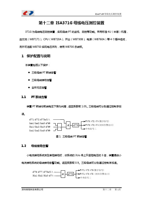
1保护配置与说明本装置包括以下保护:●三段母线PT断线告警●三段母线接地告警●全所无压告警1.1PT断线告警装置PT断线均取线电压下降为判据,返回系数取1.05。
三段母线可分别通过控制字投退。
d771/d772/d773=投入Uab1/Uab2/Uab3<d769Ubc1/Ubc2/Ubc3<d769 Uca1/Uca2/Uca3<d769≥1&F470/472/474(数字信号)中央信号二•d770 对应告警出口)图1. 三段母线PT断线告警1.2母线接地告警小电流接地系统发生单相接地时,该系统的3Uo将上升至相电压的3倍,装置提供小电流接地系统的母线接地告警功能。
返回系数取0.9。
三段母线可分别通过控制字投退。
d776/d777/d778=投入3Uo1/3Uo2/3Uo3>d774 &F471/473/475(数字信号)中央信号二•d775 F471/473/475 (对应告警出口)图2. 三段母线接地告警1.3 全所无压告警当三段母线的全部线电压均小于定值时认为全所无压,返回系数取1.05。
Uab2<d873 Ubc2<d873 F476(数字信号)中央信号二•d780 Uca1<d873Ubc1<d873 Uab1<d873 d779=投入Uca2<d873Uab3<d873 Ubc3<d873 Uca3<d873 F476(对应告警出口) && & &图3. 全所无压告警2 保护配置及整定说明2.1保护元件配置保护元件配置是根据用户的要求,在出厂前投入选配的元件。
- 1、下载文档前请自行甄别文档内容的完整性,平台不提供额外的编辑、内容补充、找答案等附加服务。
- 2、"仅部分预览"的文档,不可在线预览部分如存在完整性等问题,可反馈申请退款(可完整预览的文档不适用该条件!)。
- 3、如文档侵犯您的权益,请联系客服反馈,我们会尽快为您处理(人工客服工作时间:9:00-18:30)。
CG
Higher Capacitance, Low ESR, High ripple current.Load life of 2000 hours at 105°C.
SMD type : Lead free reflow soldering condition at 260°C peak correspondence.Adapted to the RoHS directive (2002/95/EC ).
series
–55 to +105°C 2.5 to 16V 47 to 3300µF
± 20% at 120Hz, 20°C
Not more than value of Standard ratings at 120Hz, 20°C Not more than value of Standard ratings at 100kHz, 20°C
Not more than value of Standard ratings. After 2 minute's application of rated voltage. 20°C
Z+105°C / Z+20°C 1.25 (100kHz )Z -55°C / Z +20°C 1.25
After 2000 hours' application of rated voltage
at 105°C, capacitors meet the specified value for life characteristics listed at right.
After 1000 hours' application of rated voltage
at 60°C 90%RH, capacitors meet the specified value for life characteristics listed at right.
To comply with recommended conditions for reflow soldering. Pre-heating shall be done at 150 to 200°C and for 60 to 180 sec.In the case of peak temp, less than 250°C,
reflow soldering shall be within two times.In the case of peak temp, less than 260°C,reflow soldering shall be once.
Measurement for solder temperature profile shall be made at the capacitor top and the terminal.
Navy blue print on the case top.
CONDUCTIVE POLYMER
ALUMINUM SOLID ELECTROLYTIC CAPACITORS
1 ESR measurements should be made at a point on the terminal nearest where the ternimals protrude through the plastic platform.
2 Conditioning : If there is doubt about the measured result, measurement should be made again after the rated voltage is applied for 120 minutes at the temperature of 105°C.
3 Initial value : The value before test of examination of resistance to soldering.
Item
Performance Characteristics
Category Temperature Range Rated Voltage Range Rated Capacitance Range Capacitance Tolerance tan δESR ( 1)
Leakage Current ( 2)
Characteristics of Temperature Impedance Ratio
Endurance
Damp Heat
Resistance to Soldering Heat
Marking
Capacitance change tan δESR ( 1)
Leakage current ( 2)
Within ± 20% of initial value ( 3)150% or less of the initial specified value 150% or less of the initial specified value Initial specified value or less
Capacitance change tan δESR ( 1)
Leakage current ( 2)
Within ± 20% of initial value ( 3)150% or less of the initial specified value 150% or less of the initial specified value Initial specified value or less
Capacitance change tan δESR ( 1)
Leakage current ( 2)
Within ± 10% of initial value ( 3)130% or less of the initial specified value 130% or less of the initial specified value Initial specified value or less
Specifications
Chip Type, Higher Capacitance
CG
Higher Capacitance
φ10 × 10L φ10 × 8L series
CG
CONDUCTIVE POLYMER
ALUMINUM SOLID ELECTROLYTIC CAPACITORS
P 1
C 2
G 3
04
J 5
46
77
18
M 9
C 10L 11112G 13S
14
Capacitance tolerance (±20%)
Rated Capacitance (470µF )
Rated voltage (6.3V )
Series name
Configuration
T aping code T ype
Dimensions
Type numbering system (Example : 6.3V 470µF)
Standard ratings
φD L A B 6.3φ6.3 × 6L φ8 × 7L 5.97.36.68.06.99.08.3Size 10.07.911.010.310.09.911.010.3C E H
6.62.10.5 ~ 0.8
5.0φ5 × 6L 5.9
6.05.35.31.20.5 ~ 0.8
8.33.20.8 ~ 1.1
10.34.60.8 ~ 1.1
10.34.60.8 ~ 1.1
φ10 × 12.7L
10.012.611.010.310.34.60.8 ~ 1.1
(mm)
Printed in Japan T .2007.B.3C
Design, Specifications are subject to change without notice.
V
Code
2.5e
4g
Voltage
6.3j
10A
16C。