SMCJ33CA中文资料
5.0SMLJ22CA中文资料
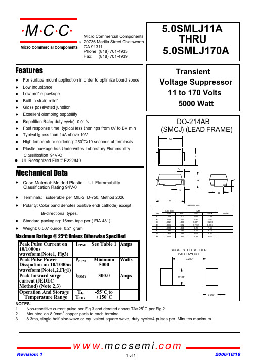
FeaturesMechanical DataTerminals: solderable per MIL-STD-750, Method 2026 Polarity: Color band denotes positive end( cathode) exceptBi-directional types.Standard packaging: 16mm tape per ( EIA 481). Weight: 0.007 ounce, 0.21 gramMaximum Ratings @ 25o C Unless Otherwise SpecifiedPeak Pulse Current on 10/1000uswaveform(Note1, Fig3)I PPM See Table 1Amps Peak Pulse Power Disspation on 10/1000us waveform(Note1,2,Fig1)P PPMMinimum 5000Watts Peak forward surge current (JEDEC Method) (Note 2,3)I FSM)300.0Amps Operation And Storage Temperature Range T J ,T STG -55o C to +150o CNOTES:1.Non-repetitive current pulse per Fig.3 and derated above TA=25oC per Fig.2.2.Mounted on 8.0mm 2copper pads to each terminal.3.8.3ms, single half sine-wave or equivalent square wave, duty cycle=4 pulses per. Minutes maximum.For surface mount application in order to optimize board space Low inductance Low profile package Built-in strain relief Glass passivated junction Excellent clamping capability Repetition Rate( duty cycle): 0.01%Fast response time: typical less than 1ps from 0V to BV min Typical I D less than 1uA above 10VHigh temperature soldering: 250oC/10 seconds at terminals Plastic package has Underwrites Laboratory FlammabilityClassification 94V-Oomp onents 20736 Marilla Street Chatsworth! "# $ % ! "#Revision: 1 2006/10/18 UL Recognized File # E222849TMMicro Commercial ComponentsCase Material: Molded Plastic. UL Flammability Classification Rating 94V-0www.mccsemi .com1 of 4MAXIMUM CLAMPING VOLTAGE REVERSE LEAKAGE @Ipp @V RWM Vc(V)I D (µA)5.0SMLJ 11A 1112.213.51018.22758005PEN 5.0SMLJ 12A 1213.314.71019.92528005PEP 5.0SMLJ 13A 1314.415.91021.52335005PEQ 5.0SMLJ 14A 1415.617.21023.22162005PER 5.0SMLJ 15A 1516.718.5124.42051005PES 5.0SMLJ 16A 1617.819.7126193505PET 5.0SMLJ 17A 1718.920.9127.6181205PEU 5.0SMLJ 18A 182022.1129.2172105PEV 5.0SMLJ 20A 2022.224.5132.415555PEW 5.0SMLJ 22A 2224.426.9135.514155PEX 5.0SMLJ 24A 2426.729.5138.912955PEZ 5.0SMLJ 26A 2628.931.9142.111955PFE 5.0SMLJ 28A 2831.134.4145.411055PFG 5.0SMLJ 30A 3033.336.8148.410355PFK 5.0SMLJ 33A 3336.740.6153.393.955PFM 5.0SMLJ 36A 364044.2158.186.155PFP 5.0SMLJ 40A 4044.449.1164.577.655PFR 5.0SMLJ 43A 4347.852.8169.472.155PFT 5.0SMLJ 45A 455055.3172.768.855PFV 5.0SMLJ 48A 4853.358.9177.464.755PFX 5.0SMLJ 51A 5156.762.7182.460.755PFZ 5.0SMLJ 54A 546066.3187.157.555RGE 5.0SMLJ 58A 5864.471.2193.653.555PGG 5.0SMLJ 60A 6066.773.7196.851.755PGK 5.0SMLJ 64A 6471.178.6110348.655PGM 5.0SMLJ 70A 7077.886111344.355PGP 5.0SMLJ 75A 7583.392.1112141.455PGR 5.0SMLJ 78A 7886.795.8112639.755PGT 5.0SMLJ 85A 8594.4104113736.555PGV 5.0SMLJ 90A 90100111114634.355PGX 5.0SMLJ 100A 100111123116230.955PGZ 5.0SMLJ 110A 110122135117728.355PHE 5.0SMLJ 120A 12013314711932655PHG 5.0SMLJ 130A 13014415912092455PHK 5.0SMLJ 150A 150167185124320.655PHM 5.0SMLJ 160A 160178197125919.355PHP 5.0SMLJ 170A170189209127518.255PHRDEVICE MARKING CODE PART NUMBERPEAK PULSE CURRENT Ipp (A)TEST CURRENT I T (mA)BREAKDOWNVOLTAGE V BR (V)MAX.@ITBREAKDOWN VOLTAGEV BR (V)MIN.@IT REVERSE STAND- OFF VOLTAGE V RWM (V)TMMicro Commercial Components5.0SMLJ11A~5.0SMLJ170Awww.mccsemi .com2 of 4Revision: 1 2006/10/18MAXIMUM CLAMPING VOLTAGE REVERSE LEAKAGE @Ipp @V RWM Vc(V)I D (µA)5.0SMLJ 11CA 1112.213.51018.22758005BEN 5.0SMLJ 12CA 1213.314.71019.92528005BEP 5.0SMLJ 13CA 1314.415.91021.52335005BEQ 5.0SMLJ 14CA 1415.617.21023.22162005BER 5.0SMLJ 15CA 1516.718.5124.42051005BES 5.0SMLJ 16CA 1617.819.7126193505BET 5.0SMLJ 17CA 1718.920.9127.6181205BEU 5.0SMLJ 18CA 182022.1129.2172105BEV 5.0SMLJ 20CA 2022.224.5132.415555BEW 5.0SMLJ 22CA 2224.426.9135.514155BEX 5.0SMLJ 24CA 2426.729.5138.912955BEZ 5.0SMLJ 26CA 2628.931.9142.111955BFE 5.0SMLJ 28CA 2831.134.4145.411055BFG 5.0SMLJ 30CA 3033.336.8148.410355BFK 5.0SMLJ 33CA 3336.740.6153.393.955BFM 5.0SMLJ 36CA 364044.2158.186.155BFP 5.0SMLJ 40CA 4044.449.1164.577.655BFR 5.0SMLJ 43CA 4347.852.8169.472.155BFT 5.0SMLJ 45CA455055.3172.768.855BFVPART NUMBERREVERSE STAND- OFF VOLTAGE V RWM (V)BREAKDOWN VOLTAGEV BR (V)MIN.@IT BREAKDOWNVOLTAGE V BR (V)MAX.@ITTEST CURRENT I T (mA)PEAK PULSE CURRENT Ipp (A)DEVICE MARKING CODE TMMicro Commercial Components5.0SMLJ11C A~5.0SMLJ 45C AFor Bidirectional type having Vrwm of 20 volts and less,the Ir limit is double.www.mccsemi .com3 of 4Revision: 1 2006/10/18Revision: 12006/10/18Micro Commercial Componentswww.mccsemi .com4 of 4products are represented on our website, harmless against all damages.***APPLICATIONS DISCLAIMER******IMPORTANT NOTICE***Aerospace or Military Applications.Products offer by Micro Commercial Components Corp .are not intended for use in Medical,Micro Commercial Components Corp .reserve s the right to make changes without further notice to any product herein to make corrections, modifications , enhancements , improvements , or other changes .Micro Commercial Components Corp .does not assume any liability arising out of the application or use of any product described herein; neither does it convey any license under its patent rights ,nor the rights of others . The user of products in such applications shall assume all risks of such use and will agree to hold Micro Commercial Components Corp .and all the companies whose。
TVS SMC乐晨系列规格书

SMCJ5.0A(CA) - SMCJ440A(CA)VOLTAGE RANGE: 5.0 - 440 VPOWER: 1500Wa t 1of 5Maximum Ratings @ T A = 25°C unless otherwise specifiedCharacteristicSymbol Value Unit Peak Pulse Power Dissipation(Non repetitive current pulse derated above T A =25°C)(Note 1)P PK 1500W Peak Forward Surge Current, 8.3ms Single Half Sine Wave Superimposed on Rated Load(JEDEC Method)(Notes 1,2,&3)I FSM 200A Steady State Power Dissipation @ T L = 75°C PM (AV) 5.0W Instantaneous Forward Voltage @I PP = 100A (Notes 1 & 3)V F See Note 5V Operating Temperature Range T j -55 to +150°C Storage Temperature RangeT STG-55 to +175°CGlass Passivated Die Construction Uni- and Bi-Directional Versions Available Excellent Clamping CapabilityFast Response TimeFeatures2. Thermal Resistance junction to Lead.NOTES:1. Non-repetitive current pulse ,per Fig. 3and derated above T A =25℃ per Fig. 1. 3. 8.3ms single half-wave duty cycle=4pulses per minutesmaximum (uni-directional units only).!!!!Classification Rating 94V-OPlastic Case Material has UL Flammability !Case: SMC/DO-214AB, Molded PlasticTerminals: Solder Plated, Solderable per MIL-STD-750, Method 2026Polarity: Cathode Band or Cathode Notch Marking: Type NumberWeight: 0.21 grams (approx.)Mechanical Data!!!!!SURFACE MOUNT TRANSIENT VOLTAGE SUPPESSOR DIODERWM RWMS tand-Off 10.020.011.19.09.08.58.08.07.57.57.06.56.56.05.0Breakdown Marking Reverse Voltage Voltage Min. @I T Breakdown Voltage Max. @ I T TestCurrentMaximum Clamping Voltage @I PPPeak Pulse Current Reverse Leakage @V (Uni)(Bi)V (V)V BR MIN (V)V BR MAX (V)I T (mA)V C (V) I PP (A) I R (uA) SMCJ5.0 SMCJ5.0C GDD BDD 6.40 7.55 10.0 9.6 156.3 800.0SMCJ5.0A SMCJ5.0CA GDE BDE 5.0 6.40 7.259.2 163.0 800.0SMCJ6.0 SMCJ6.0C GDF BDF 6.67 8.45 10.0 11.4 131.6 800.0 SMCJ6.0A SMCJ6.0CA GDG BDG 6.0 6.67 7.67 10.3 145.6 800.0SMCJ6.5 SMCJ6.5C GDH BDH 7.22 9.1410.0 12.3 122.0 500.0 SMCJ6.5A SMCJ6.5CA GDK BDK 7.22 8.30 10.0 11.2133.9 500.0 SMCJ7.0 SMCJ7.0C GDL BDL 7.78 9.86 10.0 13.3 112.8 200.0 SMCJ7.0A SMCJ7.0CA GDM BDM 7.0 7.78 8.95 12.0 125.0 200.0 SMCJ7.5 SMCJ7.5C GDN BDN 8.33 10.67 1.0 14.3 104.9 100.0 SMCJ7.5A SMCJ7.5CA GDP BDP 8.33 9.58 1.0 12.9 116.3 100.0 SMCJ8.0 SMCJ8.0C GDQ BDQ 8.89 11.3 1.0 15.0 100.0 50.0 SMCJ8.0A SMCJ8.0CA GDR BDR 8.89 10.23 1.0 13.6 110.3 50.0 SMCJ8.5 SMCJ8.5C GDS BDS 9.44 11.92 15.9 94.3 20.0 SMCJ8.5A SMCJ8.5CA GDT BDT 8.5 9.44 10.82 14.4104.2 20.0 SMCJ9.0 SMCJ9.0C GDU BDU 10.0 12.6 1.0 16.9 88.8 10.0 SMCJ9.0A SMCJ9.0CA GDV BDV 10.0 11.5 1.0 15.4 97.4 10.0 SMCJ10 SMCJ10C GDWBDW 10 14.11.0 18.8 79.8 5.0 SMCJ10A SMCJ10CA GDX BDX 10 11.112.8 1.0 17.0 88.2 5.0SMCJ11 SMCJ11C GDYBDY 1112.2 15.41.0 20.1 74.6 5.0SMCJ11A SMCJ11CA GDZ BDZ1112.2 14.0 1.0 18.2 82.4 5.0SMCJ12 SMCJ12C GED BED 12 13.3 16.9 1.0 22.0 68.2 5.0 SMCJ12A SMCJ12CA GEE BEE 12 13.3 15.3 1.0 19.9 75.4 5.0SMCJ13 SMCJ13C GEF BEF 13 14.4 18.2 1.0 23.8 63.0 5.0SMCJ13A SMCJ13CA GEG BEG 13 14.4 16.5 1.0 21.5 69.8 5.0SMCJ14 SMCJ14C GEHBEH 14 15.6 19.8 1.0 25.8 58.1 5.0 SMCJ14A SMCJ14CA GEK BEK 14 15.6 17.9 1.0 23.2 64.7 5.0SMCJ15 SMCJ15C GEL BEL 15 16.7 21.11.0 26.9 55.8 5.0SMCJ15A SMCJ15CA GEM BEM 15 16.7 19.2 1.0 24.4 61.5 5.0SMCJ16 SMCJ16C GENBEN 16 17.8 22.6 1.0 28.8 52.1 5.0 SMCJ16A SMCJ16CA GEP BEP1617.8 20.5 1.0 26.0 57.7 5.0SMCJ17 SMCJ17C GEQ BEQ 17 18.9 23.9 1.0 30.5 49.2 5.0SMCJ17A SMCJ17CA GER BER1718.9 21.71.0 27.6 54.3 5.0SMCJ18 SMCJ18C GES BES 18 25.3 1.0 32.2 46.6 5.0 SMCJ18A SMCJ18CA GET BET1820.0 23.3 1.0 29.2 51.4 5.0SMCJ20 SMCJ20C GEU BEU 20 22.2 28.1 1.0 35.8 41.9 5.0SMCJ20A SMCJ20CA GEV BEV2022.2 25.5 1.0 32.4 46.3 5.0SMCJ22 SMCJ22C GEW BEW 22 24.4 30.9 1.0 39.4 38.1 5.0 SMCJ22A SMCJ22CA GEX BEX2224.4 28.0 1.0 35.5 42.3 5.010.0 10.0 1.0 1.0 TYPE2 of 5(Uni)(Bi)26.7SMCJ24 SMCJ24C GEY BEY 24 33.8 1.0 43.0 34.9 5.0SMCJ24A SMCJ24CA GEZ BEZ2426.730.7 1.0 38.9 38.6 5.0BJS BJVGJVBJU GJU BJT GJT GJS SMCJ40 RWM RWM 1.094.083.0Breakdown MarkingReverse Stand-Off Voltage Voltage Min. @I T Breakdown Voltage Max. @ I T Test CurrentMaximum Clamping Voltage @I PP Peak Pulse Current ReverseLeakage @V (Uni)(Bi)V (V)V BR MIN (V)V BR MAX (V)I T (mA)V C (V)I PP (A)I R (uA)SMCJ43 SMCJ43C GFS BFS 43 47.8 60.5 1.0 76.7 19.6 5.0 SMCJ43A SMCJ43CA GFT BFT 43 47.8 54.9 1.0 69.4 21.6 5.0SMCJ45 SMCJ45C GFU BFU 45 50.0 63.3 1.0 80.3 18.7 5.0SMCJ45A SMCJ45CA GFV BFV 45 50.0 57.5 1.0 72.7 20.6 5.0SMCJ48 SMCJ48C 48 53.3 67.5 1.0 85.5 17.5 5.0 SMCJ48A SMCJ48CA 48 53.3 61.3 1.0 77.4 19.4 5.0SMCJ51 SMCJ51C 51 56.7 71.8 1.0 91.1 16.5 5.0SMCJ51A SMCJ51CA 51 56.7 65.2 1.0 82.4 18.2 5.0SMCJ54 SMCJ54C GFW BFW 54 60.0 76.0 1.0 96.3 15.6 5.0 SMCJ54A SMCJ54CA GFX BFX 54 60.0 69.0 1.0 87.1 17.2 5.0SMCJ58 SMCJ58C GFY BFY58 64.4 81.6 1.0 103 14.6 5.0SMCJ58A SMCJ58CA GFZ BFZ 58 64.4 74.1 1.0 93.6 16.0 5.0SMCJ60 SMCJ60C GGD BGD 60 66.7 84.5 1.0 107 14.0 5.0 SMCJ60A SMCJ60CA GGE BGE 60 66.7 76.7 1.0 96.8 15.5 5.0SMCJ64 SMCJ64C GGF BGF 64 71.1 90.1 1.0 114 13.2 5.0SMCJ64A SMCJ64CA GGG BGG 64 71.1 81.81.0 103 14.6 5.0SMCJ70 SMCJ70C GGH BGH 70 77.8 98.6 1.0 125 12.0 5.0 SMCJ70A SMCJ70CA GGK BGK 70 77.8 89.5 1.0 113 13.3 5.0SMCJ75 SMCJ75C GGL BGL 75 105.7 1.0 134 11.25.0SMCJ75A SMCJ75CA GGM BGM 75 83.0 95.8 121 12.45.0SMCJ78 SMCJ78C GGN BGN 78 86.0 109.8 1.0 139 10.8 5.0 SMCJ78A SMCJ78CA GGP BGP 78 86.0 99.7 1.0 126 11.9 5.0SMCJ85 SMCJ85C GGQ BGQ 85 119.2 1.0 151 9.9 5.0SMCJ85A SMCJ85CA GGR BGR 85 94.0 108.2 1.0 137 10.9 5.0SMCJ90 SMCJ90C GGS BGS 90 100 126.5 1.0 160 9.4 5.0 SMCJ90A SMCJ90CA GGT BGT 90 100 115.5 1.0 146 10.3 5.0SMCJ100 SMCJ100C GGU BGU 100111 141.01.0 179 8.4 5.0SMCJ100ASMCJ100CAGGV BGV 100 111 128.01.0 162 9.3 5.0SMCJ110 SMCJ110CGGW BGW 10 122 154.51.0 196 7.7 5.0 SMCJ110A SMCJ110CAGGXBGX110 122 140.5 1.0 1778.5 5.0TYPESMCJ30 SMCJ30C GFH BFH 30 33.3 42.2 1.0 53.5 28.0 5.0 SMCJ30A SMCJ30CA GFK BFK 30 33.3 38.3 1.0 48.4 31.0 5.0SMCJ33 SMCJ33C GFL BFL 33 36.7 46.5 1.0 59.0 25.4 5.0SMCJ33A SMCJ33CA GFM BFM 33 36.7 42.2 1.0 53.3 28.1 5.0SMCJ36 SMCJ36C GFN BFN 36 40.0 50.7 1.0 64.3 23.3 5.0 SMCJ36A SMCJ36CA GFP BFP 36 40.0 46.0 1.0 58.1 25.8 5.0SMCJ40C GFQ BFQ 40 44.4 56.3 1.0 71.4 21.0 5.0SMCJ40A SMCJ40CA GFR BFR 40 44.4 51.11.0 64.5 23.3 5.03 of 5(Uni)(Bi)SMCJ26 SMCJ26C GFD BFD 26 28.9 36.6 1.0 46.6 32.2 5.0 SMCJ26A SMCJ26CA GFE BFE 26 28.9 33.2 1.0 42.1 35.6 5.0SMCJ28 SMCJ28C GFF BFF 28 31.1 39.4 1.0 50.0 30.0 5.0SMCJ28A SMCJ28CA GFG BFG 28 31.1 35.8 1.0 45.4 33.0 5.0RWM RWMBreakdown MarkingReverse Stand-Off Voltage Voltage Min. @I T Breakdown Voltage Max. @ I T Test CurrentMaximum Clamping Voltage @I PP Peak Pulse Current ReverseLeakage @V (Uni)(Bi)V (V)V BR MIN (V)V BR MAX (V)I T (mA)V C (V)I PP (A)I R (uA)TYPESMCJ200 SMCJ200C GHW BHW 200 222 282.0 1.0 356 4.2 5.0 SMCJ200A SMCJ200CA GHX BHX 200222256.0 1.0322 4.7 5.0SMCJ210 SMCJ210C GHY BHY 210 233 296.1 1.0 375 4.0 5.0SMCJ210A SMCJ210CA GHZ BHZ 210233268.8 1.0339 4.4 5.0SMCJ220 SMCJ220C GJD BJD 220 244 310.2 1.0 392 3.8 5.0 SMCJ220A SMCJ220CA GJE BJE 220244281.6 1.0355 4.25.0SMCJ250 SMCJ250C GJF BJF 250 278 342.5 1.0 447 3.4 5.0SMCJ250A SMCJ250CA GJG BJG 250278309.0 1.0403 3.7 5.0SMCJ350 SMCJ350C GJL BJL 350 389 479.5 1.0 624 2.45.0SMCJ350A SMCJ350CA GJM BJM 350389432.0 1.0565 2.7 5.0SMCJ300 SMCJ300C GJH BJH 300 333 411.0 1.0 535 2.8 5.0 SMCJ300A SMCJ300CA GJK BJK 300 333 371.0 1.0 484 3.1 5.0SMCJ400 SMCJ400C GJN BJN 400 444 548.0 1.0 687 2.2 5.0 SMCJ400A SMCJ400CA GJP BJP 400444494.0 1.0645 2.3 5.0SMCJ440 SMCJ440C GJQ BJQ 440 489 602.8 1.0 786 1.9 5.0SMCJ440ASMCJ440CAGJRBJR440489543.0 1.0710 2.15.0SMCJ180 SMCJ180C GHN BHN 180 200 253.8 1.0 321 4.75.0 SMCJ180A SMCJ180CA GHP BHP 180200230.4 1.0290 5.2 5.0SMCJ190 SMCJ190C GHQ BHQ 190 211 267.9 1.0 339 4.4 5.0SMCJ190A SMCJ190CA GHR BHR 190 211 243.21.0 306 4.9 5.0SMCJ160 SMCJ160C GHH BHH 160 178 226.0 1.0 287 5.2 5.0 SMCJ160A SMCJ160CA GHK BHK 160 178 205.0 1.0 259 5.8 5.0SMCJ170 SMCJ170C GHL BHL 170 189 239.5 1.0 304 4.9 5.0SMCJ170A SMCJ170CA GHM BHM 170 189 217.51.0275 5.5 5.04 of 5(Uni)(Bi)SMCJ120 SMCJ120C GGY BGY 120 133 169.0 1.0 214 7.0 5.0SMCJ120A SMCJ120CA GGZ BGZ 120 133 153.0 1.0 193 7.8 5.0SMCJ130 SMCJ130C GHD BHD 130 144 182.5 1.0 231 6.5 5.0 SMCJ130A SMCJ130CA GHE BHE 130144165.51.0209 7.2 5.0SMCJ150 SMCJ150C GHF BHF 150 167 211.5 1.0 268 5.6 5.0SMCJ150A SMCJ150CA GHG BHG 150167192.51.0243 6.2 5.0Ratings and Characteristic Curves T A=25°C unless otherwise noted5 of 5。
SMCJ40CA中文资料
10 10 10 10 1 1 1 1 1 1 1 1 1 1 1 1 1 1 1 1 1 1 1 1 1 1 1 1 1 1 1 1 1 1 1 1 1 1 1 1 1 1 1 1 1 1
9.2 10.3 11.2 12.0 12.9 13.6 14.4 15.4 17.0 18.2 19.9 21.5 23.2 24.4 26.0 27.6 29.2 32.4 35.5 38.9 42.1 45.4 48.4 53.3 58.1 64.5 69.4 72.7 77.4 82.4 87.1 93.6 96.8 103.0 113.0 121.0 126.0 137.0 146.0 162.0 177.0 193.0 209.0 243.0 259.0 275.0
7.0 7.37 7.98 8.60 9.21 9.83 10.4 11.1 12.3 13.5 14.7 15.9 17.2 18.5 19.7 20.9 22.1 24.5 26.9 29.5 31.9 34.4 36.8 40.6 44.2 49.1 52.8 55.3 58.9 62.7 66.3 71.2 73.7 78.6 86.0 92.1 95.8 104.0 111.1 123.0 135.0 147.0 159.0 185.0 197.0 209.0
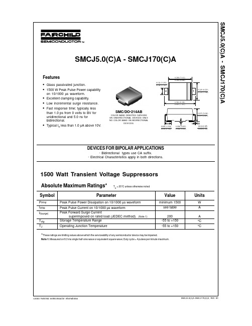
1500 Watt Transient Voltage Suppressors
Absolute Maximum Ratings*
Symbol
PPPM IPPM if(surge) Tstg TJ
TA = 25°C unless otherwise noted
Parameter
Peak Pulse Power Dissipation on 10/1000 µs waveform Peak Pulse Current on 10/1000 µs waveform Peak Forward Surge Current superimposed on rated load (JEDEC method) Storage Temperature Range Operating Junction Temperature
TVS常用哪些型号呢?

TVS常⽤哪些型号呢? ⼤家应该都知道,TVS⼆极管的型号繁多,如果选⽤错误,很容易给电⼦产品带来损伤,那么TVS⼆极管常⽤型号⼤全你了解多少呢,今天东沃电⼦就带领⼤家⼀起来了解⼀下,⼀起来看看详细介绍吧: 1)TVS⼆极管SMAJ系列常⽤型号有: SMAJ5.0CA、SMAJ15CA、SMAJ36CA、SMAJ440A、SMAJ440CA; 2)TVS⼆极管SMF系列常⽤型号有: SMF33CA、SMF36CA、SMF36A、SMF5.0CA、SMF10CA; 3)TVS⼆极管SMBJ系列常⽤型号有: SMBJ5.0CA、SMBJ6.5CA、SMBJ8.0CA、SMBJ15CA、SMBJ22CA、SMBJ24CA、SMBJ26CA、SMBJ30CA、SMBJ36CA、SMBJ440CA; 4)TVS⼆极管SMCJ系列常⽤型号有: SMCJ18A、SMCJ24A、SMCJ24CA、SMCJ30CA、SMCJ33CA、SMCJ33A、SMCJ36A、 SMCJ36CA、SMCJ48A、SMCJ48CA、SMCJ58A、SMCJ64CA; 5)TVS⼆极管P6KE系列TVS管常⽤型号有: P6KE6.8CA、P6KE12CA、P6KE15CA、P6KE22CA、P6KE30CA、P6KE33CA、P6KE36CA、 P6KE150A、P6KE150CA、P6KE350CA、P6KE400A、P6KE400CA、P6KE440A、P6KE440CA、P6KE500A、P6KE500CA、P6KE550A、P6KE550CA、P6KE600A、P6KE600CA; 6)TVS⼆极管1.5KE系列常⽤型号有: 1.5KE6.8A、1.5KE6.8CA、1.5KE18A、1.5KE18CA、1.5KE27A、1.5KE27CA、1.5KE33A、1.5KE33CA、1.5KE440CA; 7)TVS⼆极管3KP系列常⽤型号有: 3KP33CA; 8)TVS⼆极管5KP系列常⽤型号有: 5KP6.5A、5KP6.5CA; 9)TVS⼆极管15KP系列常⽤型号有: 15KP18A、15KP24A、15KP26A、15KP33A; 10)TVS⼆极管SMDJ系列常⽤型号有: SMDJ24A、SMDJ24CA、SMDJ33CA; 11)TVS⼆极管5.0SMDJ系列常⽤型号有 5.0SMDJ24A、5.0SMDJ24CA、5.0SMDJ36A、5.0SMDJ36CA、5.0SMDJ64A、5.0SMDJ68A、5.0SMDJ70A; 12)TVS⼆极管SM8S系列常⽤型号有: SM8S18A、SM8S24A 、SM8S26CA、SM8S30A、SM8S33A 以上TVS管的型号就是在电⼦产品中⽐较常⽤的了,选型⽅⾯如果不太懂也可以关注⼩编咨询,TVS选型还需要在专业技术指导下进⾏选择。
SMC真空电磁阀介绍
或存在有真空状态的回路中,故必须选用能在真空压力条件下工作的换向阀。真空换向阀要求不泄露,且
不用油雾润滑。故使用座阀式和膜片式阀芯结构比较理想。通径大时可使用外部先导式电磁阀。不给油润
滑的软质密封滑阀,由于其通用性强,也常作为真空用换向阀使用。
SMC 真空电磁阀的选用; 真空选择阀可控制吸盘对工件的吸着或脱离,一个 阀两个功能,可以简化回路设计。 供给阀印设置于正压管路中,可选用一般换向阀。 真空破坏阀,真空切换阀和真空选择阀设置于真空回路或存在有真空状态的回路 中 ,故必须选用能在真空压力条件下工作的换向阀。 真空换向阀要求不泄露,且不用油雾润滑。 故使用座阀式和膜片式阀芯结构比较理想。通径大时可使用外部先导式电磁阀。 不给油润滑的软质密封滑阀,由于其通用性强,也常作为真空用换向阀使用。. 使用真空发生器的回路中的换向阀,有供给阀和真空破坏阀。 使用真空泵回路中的换向阀,有真空切换阀和真空选择阀。 供给阀是供给真空发生器压缩空气的阀。 真空破坏阀是破坏吸盘内的真空状态,将真空变成大气压或正压力,使工件脱离 吸盘的阀。 真空切换阀就是接通或断开真空压力源的阀。
关于 SMC 真空电磁阀的选用
SMBJ15CA中文资料

S M B J15C A中文资料(总5页) -CAL-FENGHAI.-(YICAI)-Company One1-CAL-本页仅作为文档封面,使用请直接删除SMBJ5.0(C)A - SMBJ440(C)A600W Surface Mount Transient Voltage Suppressor Features600W Peak Pulse Power Dissipation5.0V - 440V Standoff VoltagesGlass Passivated Die ConstructionUni- and Bi-Directional Versions Available Excellent Clamping CapabilityFast Response TimePlastic Material - UL FlammabilityClassification Rating 94V-0Mechanical DataCase: SMB, Transfer Molded EpoxyTerminals: Solderable per MIL-STD-202,Method 208Polarity Indicator: Cathode Band(Note: Bi-directional devices have no polarityindicator.)Marking: Date Code and Marking CodeSee Page 2Weight: 0.1 grams (approx.)MAXIMUM RATINGSRating at Ta = 25 C ambient temperature unless otherwise specified.DO-214AA (SMB)0.083(2.11) 0.155(3.94) 0.075(1.91) 0.130(3.30)0.185(4.70)0.160(4.06)0.012(0.31)0.006(0.15) 0.096(2.44)0.083(2.13)0.050(1.27) 0.008(0.203)0.030(0.76) MAX.0.220(5.59)0.200(5.08)Dimensions in inches and (millimeters)Rating Symbol Value UnitsPeak Pulse Power Dissipation on 10/1000μs (1)waveform (Notes 1, 2, Fig. 3) P PPM Minimum 600 Watts Peak Pulse Current on 10/1000μswaveform (Note 1, Fig. 5) I PPM See Table Amps Peak forward Surge Current8.3 ms single half sine-wave superimposed onrated load ( JEDEC Method )(Notes 2, 3)Maximum Instantaneous Forward Voltage at 50A V FM See Note 3, 4 VoltsOperating Junction and Storage Temperature Range T J, T STG - 65 to + 150 C Note :(1) Non-repetitive Current pulse, per Fig. 5 and derated above Ta = 25 C per Fig. 1(2) Mounted on 5.0mm2 (0.013mm thick) land areas.(3) Measured on 8.3ms. Single half sine-wave or equivalent square wave, duty cycle = 4 pulses per minutes maximum.SMBJ15CATYPE MarkingReverse Breakdown Stand-Off Voltage Voltage Min. @I T BreakdownVoltage TestMax. @ I T CurrentMaximumClampingVoltage@I PPPeak ReversePulse LeakageCurrent @V RMW(Uni) (BI) (Uni) (Bi) V (V) V(V) V(V) I T (mA) V(V) I PP(A) I R(uA) SMBJ5.0 SMBJ5.0C KD AD 5.0 6.40 7.55 10 9.6 62.5 800.0 SMBJ5.0A SMBJ5.0CA KE AE 5.0 6.40 7.25 10 9.2 65.2 800.0 SMBJ6.0 SMBJ6.0C KF AF 6.0 6.67 8.45 10 11.4 52.6 800.0 SMBJ6.0A SMBJ6.0CA KG AG 6.0 6.67 7.67 10 10.3 58.3 800.0 SMBJ6.5 SMBJ6.5C KH AH 6.5 7.22 9.14 10 12.3 48.8 500.0 SMBJ6.5A SMBJ6.5CA KK AK 6.5 7.22 8.30 10 11.2 53.6 500.0 SMBJ7.0 SMBJ7.0C KL AL 7.0 7.78 9.86 10 13.3 45.1 200.0 SMBJ7.0A SMBJ7.0CA KM AM 7.0 7.78 8.95 10 12.0 50.0 200.0 SMBJ7.5 SMBJ7.5C KN AN 7.5 8.33 10.67 1.0 14.3 42.0 100.0 SMBJ7.5A SMBJ7.5CA KP AP 7.5 8.33 9.58 1.0 12.9 46.5 100.0 SMBJ8.0 SMBJ8.0C KQ AQ 8.0 8.89 11.3 1.0 15.0 40.0 50.0 SMBJ8.0A SMBJ8.0CA KR AR 8.0 8.89 10.23 1.0 13.6 44.1 50.0 SMBJ8.5 SMBJ8.5C KS AS 8.5 9.44 11.92 1.0 15.9 37.7 20.0 SMBJ8.5A SMBJ8.5CA KT AT 8.5 9.44 10.82 1.0 14.4 41.7 20.0 SMBJ9.0 SMBJ9.0C KU AU 9.0 10.0 12.6 1.0 16.9 35.5 10.0 SMBJ9.0A SMBJ9.0CA KV AV 9.0 10.0 11.5 1.0 15.4 39.0 10.0 SMBJ10 SMBJ10C KW AW 10 11.1 14.1 1.0 18.8 31.9 5.0 SMBJ10A SMBJ10CA KX AX 10 11.1 12.8 1.0 17.0 35.3 5.0 SMBJ11 SMBJ11C KY AY 11 12.2 15.4 1.0 20.1 29.9 5.0 SMBJ11A SMBJ11CA KZ AZ 11 12.2 14.0 1.0 18.2 33.0 5.0 SMBJ12 SMBJ12C LD BD 12 13.3 16.9 1.0 22.0 27.3 5.0 SMBJ12A SMBJ12CA LE BE 12 13.3 15.3 1.0 19.9 30.2 5.0 SMBJ13 SMBJ13C LF BF 13 14.4 18.2 1.0 23.8 25.2 5.0 SMBJ13A SMBJ13CA LG BG 13 14.4 16.5 1.0 21.5 27.9 5.0 SMBJ14 SMBJ14C LH BH 14 15.6 19.8 1.0 25.8 23.3 5.0 SMBJ14A SMBJ14CA LK BK 14 15.6 17.9 1.0 23.2 25.9 5.0 SMBJ15 SMBJ15C LL BL 15 16.7 21.1 1.0 26.9 22.3 5.0 SMBJ15A SMBJ15CA LM BM 15 16.7 19.2 1.0 24.4 24.6 5.0 SMBJ16 SMBJ16C LN BN 16 17.8 22.6 1.0 28.8 20.8 5.0 SMBJ16A SMBJ16CA LP BP 16 17.8 20.5 1.0 26.0 23.1 5.0 SMBJ17 SMBJ17C LQ BQ 17 18.9 23.9 1.0 30.5 19.7 5.0 SMBJ17A SMBJ17CA LR BR 17 18.9 21.7 1.0 27.6 21.7 5.0 SMBJ18 SMBJ18C LS BS 18 20.0 25.3 1.0 32.2 18.6 5.0 SMBJ18A SMBJ18CA LT BT 18 20.0 23.3 1.0 29.2 20.5 5.0 SMBJ20 SMBJ20C LU BU 20 22.2 28.1 1.0 35.8 16.8 5.0 SMBJ20A SMBJ20CA LV BV 20 22.2 25.5 1.0 32.4 18.5 5.0 SMBJ22 SMBJ22C LW BW 22 24.4 30.9 1.0 39.4 15.2 5.0 SMBJ22A SMBJ22CA LX BX 22 24.4 28.0 1.0 35.5 16.9 5.0 SMBJ24 SMBJ24C LY BY 24 26.7 33.8 1.0 43.0 14.0 5.0 SMBJ24A SMBJ24CA LZ BZ 24 26.7 30.7 1.0 38.9 15.4 5.0 SMBJ26 SMBJ26C MD CD 26 28.9 36.6 1.0 46.6 12.9 5.0 SMBJ26A SMBJ26CA ME CE 26 28.9 33.2 1.0 42.1 14.3 5.0 SMBJ28 SMBJ28C MF CF 28 31.1 39.4 1.0 50.0 12.0 5.0 SMBJ28A SMBJ28CA MG CG 28 31.1 35.8 1.0 45.4 13.2 5.0 Note:( 1 ) V measured after I applied for 300 s., I = square wave pulse or equivalent. ( 2 )Surge Current Waveform per Figure 5 and Derate per Figure 1( 3 ) A Transient suppressor is normally selected according to the reverse " Stand-off Voltage " (V) which should beequal to or greater then the D.C. or continuous peak operating voltage level.SMBJ15CAReverse Breakdown Breakdown Maximum Peak Reverse TYPE Marking Stand-Off Voltage Voltage Test Clamping Pulse LeakageVoltage Min. @I T Max. @ I T Current Voltage @I Current @V RMW (Uni) (BI) (Uni) (Bi) V (V) V(V) V(V) I T (mA) V(V) I PP(A) I R(uA) SMBJ30 SMBJ30C MH CH 30 33.3 42.2 1.0 53.5 11.2 5.0 SMBJ30A SMBJ30CA MK CK 30 33.3 38.3 1.0 48.4 12.4 5.0 SMBJ33 SMBJ33C ML CL 33 36.7 46.5 1.0 59.0 10.2 5.0 SMBJ33A SMBJ33CA MM CM 33 36.7 42.2 1.0 53.3 11.3 5.0 SMBJ36 SMBJ36C MN CN 36 40.0 50.7 1.0 64.3 9.3 5.0 SMBJ36A SMBJ36CA MP CP 36 40.0 46.0 1.0 58.1 10.3 5.0 SMBJ40 SMBJ40C MQ CQ 40 44.4 56.3 1.0 71.4 8.4 5.0 SMBJ40A SMBJ40CA MR CR 40 44.4 51.1 1.0 64.5 9.3 5.0 SMBJ43A SMBJ43CA MT CT 43 47.8 54.9 1.0 69.4 8.6 5.0 SMBJ45 SMBJ45C MU CU 45 50.0 63.3 1.0 80.3 7.5 5.0 SMBJ45A SMBJ45CA MV CV 45 50.0 57.5 1.0 72.7 8.3 5.0 SMBJ48 SMBJ48C MW CW 48 53.3 67.5 1.0 85.5 7.0 5.0 SMBJ48A SMBJ48CA MX CX 48 53.3 61.3 1.0 77.4 7.8 5.0 SMBJ51 SMBJ51C MY CY 51 56.7 71.8 1.0 91.1 6.6 5.0 SMBJ51A SMBJ51CA MZ CZ 51 56.7 65.2 1.0 82.4 7.3 5.0 SMBJ54 SMBJ54C ND DD 54 60.0 76.0 1.0 96.3 6.2 5.0 SMBJ54A SMBJ54CA NE DE 54 60.0 69.0 1.0 87.1 6.9 5.0 SMBJ58 SMBJ58C NF DF 58 64.4 81.6 1.0 103 5.8 5.0 SMBJ58A SMBJ58CA NG DG 58 64.4 74.1 1.0 93.6 6.4 5.0 SMBJ60 SMBJ60C NH DH 60 66.7 84.5 1.0 107 5.6 5.0 SMBJ60A SMBJ60CA NK DK 60 66.7 76.7 1.0 96.8 6.2 5.0 SMBJ64 SMBJ64C NL DL 64 71.1 90.1 1.0 114 5.3 5.0 SMBJ64A SMBJ64CA NM DM 64 71.1 81.8 1.0 103 5.8 5.0 SMBJ70 SMBJ70C NN DN 70 77.8 98.6 1.0 125 4.8 5.0 SMBJ70A SMBJ70CA NP DP 70 77.8 89.5 1.0 113 5.3 5.0 SMBJ75 SMBJ75C NQ DQ 75 83.0 105.7 1.0 134 4.5 5.0 SMBJ75A SMBJ75CA NR DR 75 83.0 95.8 1.0 121 5.0 5.0 SMBJ90 SMBJ90C NW DW 90 100 126.5 1.0 160 3.8 5.0 SMBJ90A SMBJ90CA NX DX 90 100 115.5 1.0 146 4.1 5.0 SMBJ100 SMBJ100C NY DY 100 111 141.0 1.0 179 3.4 5.0 SMBJ100A SMBJ100CA NZ DZ 100 111 128.0 1.0 162 3.7 5.0 SMBJ110 SMBJ110C PD ED 110 122 154.5 1.0 196 3.1 5.0 SMBJ110A SMBJ110CA PE EE 100 122 140.5 1.0 177 3.4 5.0 SMBJ120 SMBJ120C PF EF 120 133 169.0 1.0 214 2.8 5.0 SMBJ120A SMBJ120CA PG EG 120 133 153.0 1.0 193 3.1 5.0 SMBJ130 SMBJ130C PH EH 130 144 182.5 1.0 231 2.6 5.0 SMBJ130A SMBJ130CA PK EK 130 144 165.5 1.0 209 2.9 5.0 SMBJ150 SMBJ150C PL EL 150 167 211.5 1.0 268 2.2 5.0 SMBJ150A SMBJ150CA PM EM 150 167 192.5 1.0 243 2.5 5.0 SMBJ160 SMBJ160C PN EN 160 178 226.0 1.0 287 2.1 5.0 SMBJ160A SMBJ160CA PP EP 160 178 205.0 1.0 259 2.3 5.0 Note:( 1 ) V measured after I applied for 300 s., I = square wave pulse or equivalent. ( 2 )Surge Current Waveform per Figure 5 and Derate per Figure 1( 3 ) A Transient suppressor is normally selected according to the reverse " Stand-off Voltage " (V) which should beequal to or greater then the D.C. or continuous peak operating voltage level.SMBJ15CATYPE MarkingReverse Breakdown Stand-Off Voltage Voltage Min. @I T BreakdownVoltage TestMax. @ I T CurrentMaximumClampingVoltage@I PPPeak ReversePulse LeakageCurrent @V RMW(Uni) (BI) (Uni) (Bi) V (V) V(V) V(V) I T (mA) V(V) I PP(A) I R(uA) SMBJ170 SMBJ170C PQ EQ 170 189 239.5 1.0 304 2.0 5.0 SMBJ170A SMBJ170CA PR ER 170 189 217.5 1.0 275 2.2 5.0 SMBJ180 SMBJ180C PS ES 180 200 253.8 1.0 321 1.9 5.0 SMBJ180A SMBJ180CA PT ET 180 200 230.4 1.0 290 2.1 5.0 SMBJ190 SMBJ190C PU EU 190 211 267.9 1.0 339 1.8 5.0 SMBJ190A SMBJ190CA PV EV 190 211 243.2 1.0 306 2.0 5.0 SMBJ200 SMBJ200C PW EW 200 222 282.0 1.0 356 1.7 5.0 SMBJ200A SMBJ200CA PX EX 200 222 256.0 1.0 322 1.9 5.0 SMBJ210 SMBJ210C PY EY 210 233 296.1 1.0 375 1.6 5.0 SMBJ210A SMBJ210CA PZ EZ 210 233 268.8 1.0 339 1.8 5.0 SMBJ220 SMBJ220C QD FD 220 244 310.2 1.0 392 1.5 5.0 SMBJ220A SMBJ220CA QE FE 220 244 281.6 1.0 355 1.7 5.0 SMBJ250 SMBJ250C QF FF 250 278 342.5 1.0 447 1.3 5.0 SMBJ250A SMBJ250CA QG FG 250 278 309.0 1.0 403 1.5 5.0 SMBJ300 SMBJ300C QH FH 300 333 411.0 1.0 535 1.1 5.0 SMBJ300A SMBJ300CA QK FK 300 333 371.0 1.0 484 1.2 5.0 SMBJ350 SMBJ350C QL FL 350 389 479.5 1.0 624 1.0 5.0 SMBJ350A SMBJ350CA QM FM 350 389 432.0 1.0 565 1.1 5.0 SMBJ400 SMBJ400C QN FN 400 444 548.0 1.0 687 0.9 5.0 SMBJ400A SMBJ400CA QP FP 400 444 494.0 1.0 645 0.9 5.0 SMBJ440 SMBJ440C QQ FQ 440 489 602.8 1.0 786 0.8 5.0 SMBJ440A SMBJ440CA QR FR 440 489 543.0 1.0 710 0.8 5.0SMBJ15CARatings and Characteristic Curves T A =25癈 unless otherwise notedSMBJ15CA。
SMCJ中文资料
6.40 6.40 6.67 6.67 7.22 7.22 7.78 7.78 8.33 8.33 8.89 8.89 9.44 9.44 10.0 10.0 11.1 11.1 12.2 12.2 13.3 13.3 14.4 14.4 15.6 15.6 16.7 16.7 17.8 17.8 18.9 18.9 20.0 20.0 22.2 22.2 24.4 24.4 26.7 26.7 28.9 28.9 31.1 31.1 33.3 33.3 36.7 36.7 40.0 40.0 44.4 44.4 47.8 47.8 50.0 50.0 53.3 53.3 56.7 56.7 60.0 60.0 64.4 64.4
TA, AMBIENT TEMPERATURE ( C)
FIG.3-PULSE WAVE FORM
150 IPPM, PEAK PULSE CURRENT, %
tf=10us Peak Value IPPM TA=25 C Pulse Width (td) is defined as the point where the Peak Current Deacys to 50% of Ipp 10,000
RATINGS
Peak Power Dissipation at TA =25 C, TP=1ms(NOTE 1) Peak Forward Surge Current at 8.3ms Single Half Sine-Wave superimposed on rated load (JEDEC method) (NOTE 3) Maximum Instantenous Forward Voltage at 35.0A for Unidirectional only
SCA33CA中文资料

SA5.0(C)A - SA170(C)A1:1Scale 1:1 on letter size paperDimensions shown below are in:inches [millimeters]Part Weight per unit (gram): 0.4TRADEMARKSACEx™CoolFET™CROSSVOLT™E 2CMOS TM FACT™FACT Quiet Series™FAST ®FASTr™GTO™HiSeC™The following are registered and unregistered trademarks Fairchild Semiconductor owns or is authorized to use and is not intended to be an exhaustive list of all such trademarks.LIFE SUPPORT POLICYFAIRCHILD’S PRODUCTS ARE NOT AUTHORIZED FOR USE AS CRITICAL COMPONENTS IN LIFE SUPPORTDEVICES OR SYSTEMS WITHOUT THE EXPRESS WRITTEN APPROV AL OF FAIRCHILD SEMICONDUCTOR CORPORA TION.As used herein:ISOPLANAR™MICROWIRE™POP™PowerTrench™QS™Quiet Series™SuperSOT™-3SuperSOT™-6SuperSOT™-8TinyLogic™1. Life support devices or systems are devices or systems which, (a) are intended for surgical implant intothe body, or (b) support or sustain life, or (c) whosefailure to perform when properly used in accordancewith instructions for use provided in the labeling, can be reasonably expected to result in significant injury to the user.2. A critical component is any component of a lifesupport device or system whose failure to perform can be reasonably expected to cause the failure of the life support device or system, or to affect its safety or effectiveness.PRODUCT STATUS DEFINITIONS Definition of Terms Datasheet Identification Product Status DefinitionAdvance InformationPreliminary No Identification Needed Obsolete This datasheet contains the design specifications for product development. Specifications may change in any manner without notice.This datasheet contains preliminary data, andsupplementary data will be published at a later date.Fairchild Semiconductor reserves the right to make changes at any time without notice in order to improve design.This datasheet contains final specifications. Fairchild Semiconductor reserves the right to make changes at any time without notice in order to improve design.This datasheet contains specifications on a product that has been discontinued by Fairchild semiconductor.The datasheet is printed for reference information only.Formative or In DesignFirst ProductionFull ProductionNot In ProductionDISCLAIMERFAIRCHILD SEMICONDUCTOR RESERVES THE RIGHT TO MAKE CHANGES WITHOUT FURTHER NOTICE TO ANY PRODUCTS HEREIN TO IMPROVE RELIABILITY , FUNCTION OR DESIGN. FAIRCHILD DOES NOT ASSUME ANY LIABILITY ARISING OUT OF THE APPLICATION OR USE OF ANY PRODUCT OR CIRCUIT DESCRIBED HEREIN; NEITHER DOES IT CONVEY ANY LICENSE UNDER ITS PATENT RIGHTS, NOR THE RIGHTS OF OTHERS.UHC™VCX™。
- 1、下载文档前请自行甄别文档内容的完整性,平台不提供额外的编辑、内容补充、找答案等附加服务。
- 2、"仅部分预览"的文档,不可在线预览部分如存在完整性等问题,可反馈申请退款(可完整预览的文档不适用该条件!)。
- 3、如文档侵犯您的权益,请联系客服反馈,我们会尽快为您处理(人工客服工作时间:9:00-18:30)。
Notes:
1. Valid provided that terminals are kept at ambient temperature. 2. Measured with 8.3ms single half sine-wave. Duty cycle = 4 pulses per minute maximum. 3. Unidirectional units only.
Notes:
4. Suffix C denotes Bi-directional device. 5. VBR measured with IT current pulse = 300ms 6. For Bi-Directional devices havingVRWM of 10V and under, the IR is doubled.
A
C
Mechanical Data
· · · · ·
D
J
E G H
H
G E
J
All Dimensions in mm
Maximum Ratings
Characteristic Peak Pulse Power Dissipation (Non repetitive current pulse derated above T = 25°C) A ( Note 1) Peak Forward Surge Current, 8.3ms Single Half Sine Wave Superimposed on Rated Load (JEDEC Method) (Notes 1, 2, & 3) Instantaneous Forward Voltage @ IPP = 35A (Notes 1, 2, & 3) Operating and Storage Temperature Range
DS19003 Rev. 11 - 2
1 of 3
SMCJ5.0(C)A - SMCJ170(C)A
元器件交易网
Part Number Add C For Bi-Directional (Note 4) SMCJ5.0(C)A SMCJ6.0(C)A SMCJ6.5(C)A SMCJ7.0(C)A SMCJ7.5(C)A SMCJ8.0(C)A SMCJ8.5(C)A SMCJ9.0(C)A SMCJ10(C)A SMCJ11(C)A SMCJ12(C)A SMCJ13(C)A SMCJ14(C)A SMCJ15(C)A SMCJ16(C)A SMCJ17(C)A SMCJ18(C)A SMCJ20(C)A SMCJ22(C)A SMCJ24(C)A SMCJ26(C)A SMCJ28(C)A SMCJ30(C)A SMCJ33(C)A SMCJ36(C)A SMCJ40(C)A SMCJ43(C)A SMCJ45(C)A SMCJ48(C)A SMCJ51(C)A SMCJ54(C)A SMCJ58(C)A SMCJ60(C)A SMCJ64(C)A SMCJ70(C)A SMCJ75(C)A SMCJ78(C)A SMCJ85(C)A SMCJ90(C)A SMCJ100(C)A SMCJ110(C)A SMCJ120(C)A SMCJ130(C)A SMCJ150(C)A SMCJ160(C)A SMCJ170(C)A Reverse Standoff Voltage VRWM (V) 5.0 6.0 6.5 7.0 7.5 8.0 8.5 9.0 10.0 11.0 12.0 13.0 14.0 15.0 16.0 17.0 18.0 20.0 22.0 24.0 26.0 28.0 30.0 33.0 36.0 40.0 43.0 45.0 48.0 51.0 54.0 58.0 60.0 64.0 70.0 75.0 78.0 85.0 90.0 100.0 110.0 120.0 130.0 150.0 160.0 170.0 Breakdown Voltage VBR @ IT (Note 5) Min (V) 6.40 6.67 7.22 7.78 8.33 8.89 9.44 10.00 11.10 12.20 13.30 14.40 15.60 16.70 17.80 18.90 20.00 22.20 24.40 26.70 28.90 31.10 33.30 36.70 40.00 44.40 47.80 50.00 53.30 56.70 60.00 64.40 66.70 71.10 77.80 83.30 86.70 94.40 100.00 111.00 122.00 133.00 144.00 167.00 178.00 189.00 Max (V) 7.25 7.67 8.30 8.95 9.58 10.23 10.82 11.50 12.80 14.40 15.30 16.50 17.90 19.20 20.50 21.70 23.30 25.50 28.00 30.70 33.20 35.80 38.30 42.20 46.00 51.10 54.90 57.50 61.30 65.20 69.00 74.60 76.70 81.80 89.50 95.80 99.70 108.20 115.50 128.00 140.50 153.00 165.50 192.50 205.00 217.50 Test Current IT(mA) 10 10 10 10 1.0 1.0 1.0 1.0 1.0 1.0 1.0 1.0 1.0 1.0 1.0 1.0 1.0 1.0 1.0 1.0 1.0 1.0 1.0 1.0 1.0 1.0 1.0 1.0 1.0 1.0 1.0 1.0 1.0 1.0 1.0 1.0 1.0 1.0 1.0 1.0 1.0 1.0 1.0 1.0 1.0 1.0 Max. Reverse Leakage @ VRWM(Note 6) IR (mA) 1000 1000 500 200 100 50 20 10 5.0 5.0 5.0 5.0 5.0 5.0 5.0 5.0 5.0 5.0 5.0 5.0 5.0 5.0 5.0 5.0 5.0 5.0 5.0 5.0 5.0 5.0 5.0 5.0 5.0 5.0 5.0 5.0 5.0 5.0 5.0 5.0 5.0 5.0 5.0 5.0 5.0 5.0 Max. Clamping Max. Peak Pulse Current Voltage @ Ipp Ipp VC (V) 9.2 10.3 11.2 12.0 12.9 13.6 14.4 15.4 17.0 18.2 19.9 21.5 23.2 24.4 26.0 27.6 29.2 32.4 35.5 38.9 42.1 45.4 48.4 53.3 58.1 64.5 69.4 72.7 77.4 82.4 87.1 126.0 137.0 146.0 162.0 177.0 193.0 209.0 243. 0 259. 0 275.0 (A) 163.0 145.6 133.9 125.0 116.3 110.3 104.2 97.4 88.2 82.4 75.3 69.7 64.7 61.5 57.7 53.3 51.4 46.3 42.2 38.6 35.6 33.0 31.0 28.1 25.8 23.2 21.6 20.6 19.4 18.2 17.2 16.0 15.5 14.6 13.3 12.4 11.4 10.4 10.3 9.3 8.4 7.9 7.2 6.2 5.8 5.5 Marking Code BIBDE BDG BDK BDM BDP BDR BDT BDV BDX BDZ BEE BEG BEK BEM BEP BER BET BEV BEX BEZ BFE BFG BFK BFM BFP BFR BFT BFV BFX BFZ BGE BGG BGK BGM BGP BGR BGT BGV BGX BGZ BHE BHG BHK BHM BHP BHR UNIGDE GDG GDK GDM GDP GDR GDT GDV GDX GDZ GEE GEG GEK GEM GEP GER GET GEV GEX GEZ GFE GFG GFK GFM GFP GFR GFT GFV GFX GFZ GGE GGG GGK GGM GGP GGR GGT GGV GGX GGZ GHE GHG GHK GHM GHP GHR
@ TA = 25°C unless otherwise specified Symbol PPK IFSM VF Tj, TSTG Value 1500 200 3.5 -55 to +150 Unit W A V °C
B
Dim A B C D
SMC Min 5.59 6.60 2.75 0.15 7.75 0.10 0.76 2.00 Max 6.22 7.11 3.18 0.31 8.13 0.20 1.52 2.62
元器件交易网
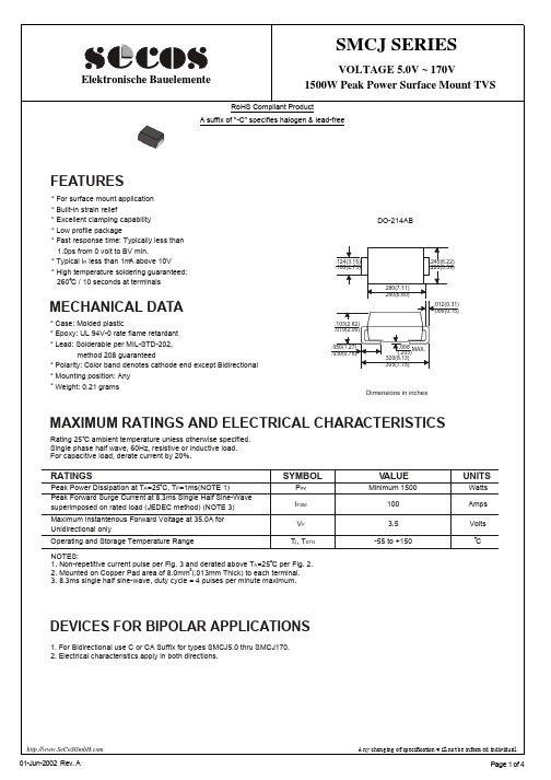
SMCJ5.0(C)A - SMCJ170(C)A
1500W SURFACE MOUNT TRANSIENT VOLTAGE SUPPRESSOR Features
· · · · · · · 1500W Peak Pulse Power Dissipation 5.0V - 170V Standoff Voltages Glass Passivated Die Construction Uni- and Bi-Directional Versions Available Excellent Clamping Capability Fast Response Time Plastic Case Material has UL Flammability Classification Rating 94V-0 Case: SMC, Transfer Molded Epoxy Terminals: Solderable per MIL-STD-202, Method 208 Polarity Indicator: Cathode Band (Note: Bi-directional devices have no polarity indicator.) Marking: Date Code and Marking Code See Page 3 Weight: 0.21 grams (approx.)