2018 年太阳及行星在香港的出没时间Times of Rise and Set of the ...
行星冲日
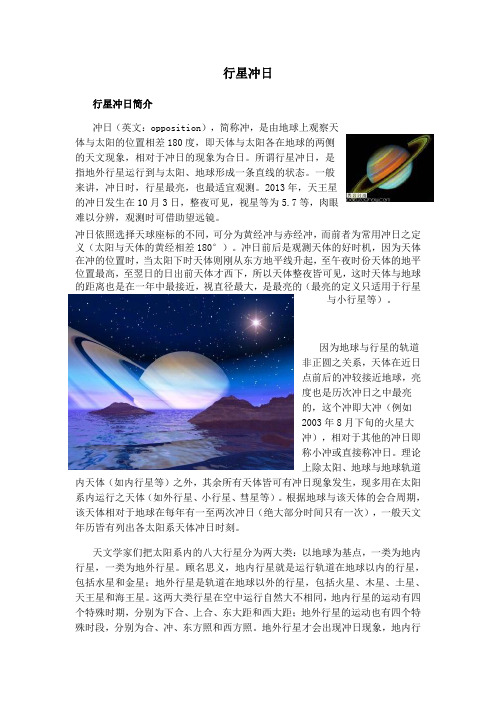
行星冲日行星冲日简介冲日(英文:opposition),简称冲,是由地球上观察天体与太阳的位置相差180度,即天体与太阳各在地球的两侧的天文现象,相对于冲日的现象为合日。
所谓行星冲日,是指地外行星运行到与太阳、地球形成一条直线的状态。
一般来讲,冲日时,行星最亮,也最适宜观测。
2013年,天王星的冲日发生在10月3日,整夜可见,视星等为5.7等,肉眼难以分辨,观测时可借助望远镜。
冲日依照选择天球座标的不同,可分为黄经冲与赤经冲,而前者为常用冲日之定义(太阳与天体的黄经相差180°)。
冲日前后是观测天体的好时机,因为天体在冲的位置时,当太阳下时天体则刚从东方地平线升起,至午夜时份天体的地平位置最高,至翌日的日出前天体才西下,所以天体整夜皆可见,这时天体与地球的距离也是在一年中最接近,视直径最大,是最亮的(最亮的定义只适用于行星与小行星等)。
因为地球与行星的轨道非正圆之关系,天体在近日点前后的冲较接近地球,亮度也是历次冲日之中最亮的,这个冲即大冲(例如2003年8月下旬的火星大冲),相对于其他的冲日即称小冲或直接称冲日。
理论上除太阳、地球与地球轨道内天体(如内行星等)之外,其余所有天体皆可有冲日现象发生,现多用在太阳系内运行之天体(如外行星、小行星、彗星等)。
根据地球与该天体的会合周期,该天体相对于地球在每年有一至两次冲日(绝大部分时间只有一次),一般天文年历皆有列出各太阳系天体冲日时刻。
天文学家们把太阳系内的八大行星分为两大类:以地球为基点,一类为地内行星,一类为地外行星。
顾名思义,地内行星就是运行轨道在地球以内的行星,包括水星和金星;地外行星是轨道在地球以外的行星,包括火星、木星、土星、天王星和海王星。
这两大类行星在空中运行自然大不相同,地内行星的运动有四个特殊时期,分别为下合、上合、东大距和西大距;地外行星的运动也有四个特殊时段,分别为合、冲、东方照和西方照。
地外行星才会出现冲日现象,地内行星是绝对不可能发生冲日。
2024届高考地理一轮总复习第一部分自然地理第二章宇宙中的地球课时跟踪练5地球自转及其地理意义
课时跟踪练5(2022·全国高三专题练习)孟晚舟乘坐中国政府包机于2021年9月24日16时29分(当地区时,采用的夏令时)从加拿大温哥华(49°13′N,123°06′W)机场起飞,于北京时间9月25日21时51分降落在中国深圳宝安机场(22°32′N,114°03′E)(图2)。
孟晚舟在飞机上感言:“此刻飞机正飞在北极……正是那一抹绚丽的中国红……引领我回家的漫长路途。
”读图,完成1~3题。
1.孟晚舟乘坐的我国政府包机从温哥华到深圳飞行了( )A.2时22分B.12时22分C.14时22分D.16时22分2.该航班航线最可能途经( )A.阿拉伯半岛B.俄罗斯东部C.美国东部D.格陵兰岛3.飞机出发时温哥华气温为15℃,飞机抵达深圳时气温为27℃,影响两地气温差异的主要因素是( )A.海陆位置B.纬度位置C.地形D.洋流解析:第1题,根据材料可知,起飞时间按照西八区区时计算,但由于是夏令时,所以实际当时西八区区时是15时29分,然后飞到深圳,用的是北京时间,时区相差16小时,用25日21时51分减去16小时,得出降落时的温哥华时间25日5时51分,再减去起飞时的温哥华时间24日15时29分,得出14时22分,C正确;A、B、D错误。
第2题,结合材料描述,飞机飞过北极上空,又根据两地经纬度,说明最可能飞过俄罗斯东部。
B正确;A、C、D错误。
第3题,出发地温哥华正值午后,到达地深圳正值夜晚,但深圳温度仍然更高,从图中可以看出深圳的纬度较低,故气温较高,故B正确;A、C、D错误。
答案:1.C 2.B 3.B(2022·浙江杭州第二中学模拟预测)天舟四号于2022年5月10日1时56分成功发射,标志着中国空间站在轨建造阶段的首次发射任务圆满成功。
中国空间站于北京时间5月18日20时左右在浙江上空过境。
据此,完成4~5题。
4.美国洛杉矶(西八区)的华侨收看火箭发射直播,选择时间为( )A.5月10日9时30分左右B.5月9日9时30分左右C.5月9日19时30分左右D.5月10日19时30分左右5.下图中(阴影部分表示黑夜)与当天傍晚天空中实际可观察到的现象相符的是( )A BC D解析:第4题,材料指出“天舟四号于2022年5月10日1时56分成功发射”,火箭发射时间为北京时间5月10日1时56分,即东八区区时为5月10日1时56分;美国洛杉矶位于西八区,东八区与西八区相差16小时,所以火箭发射直播时西八区区时:5月10日1时56分-16时=5月9日9时56分,与5月9日9时30分最为接近,B正确。
EN 420-2003+A1-2009
© 2009 CEN
All rights of exploitation in any form and by any means reserved worldwide for CEN national Members.
Ref. No. EN 420:2003+A1:2009: E
EN 420:2003+A1:2009 (E)
EUROPEAN COMMITTEE FOR STANDARDIZATION COMITÉ EUROPÉEN DE NORMALISATION EUROPÄISCHES KOMITEE FÜR NORMUNG
Management Centre: Avenue Marnix 17, B-1000 Brussels
EUROPEABiblioteka STANDARD NORME EUROPÉENNE EUROPÄISCHE NORM
ICS 13.340.40
EN 420:2003+A1
November 2009
Supersedes EN 420:2003
English Version
Protective gloves - General requirements and test methods
Contents
page
Foreword ..............................................................................................................................................................3 Introduction .........................................................................................................................................................4 1 2 3 4 4.1 4.2 4.3 4.4 4.5 5 5.1 5.2 5.3 6 6.1 6.2 6.3 6.4 7 7.1 7.2 7.3 Scope ......................................................................................................................................................5 Normative references ............................................................................................................................5 Terms and definitions ...........................................................................................................................6 General requirements ............................................................................................................................7 Glove design and construction — General .........................................................................................7 Resistance of glove materials to water penetration...........................................................................7 Innocuousness of protective gloves ...................................................................................................8 Cleaning ..................................................................................................................................................8 Electrostatic properties .........................................................................................................................9 Comfort and efficiency ..........................................................................................................................9 Sizing ......................................................................................................................................................9 Dexterity............................................................................................................................................... 11 Water vapour transmission and absorption .................................................................................... 11 Test procedures .................................................................................................................................. 11 Hand and glove measurement and dimensions .............................................................................. 11 Test method for determining gloved finger dexterity ..................................................................... 12 Test method for determination of water vapour transmission ...................................................... 13 Test method for determination of water vapour absorption .......................................................... 16 Marking and information .................................................................................................................... 18 General ................................................................................................................................................. 18 Marking ................................................................................................................................................ 18 Information supplied by the manufacturer ...................................................................................... 19
香港高三地理上册2024-2025学年同步监测试题及答案

香港高三地理上册2024-2025学年同步监测试题班级:________________ 学号:________________ 姓名:______________一、单选题(每题3分)1.下列关于地球运动的叙述,正确的是:A. 地球自转的角速度全球各地都相等B. 地球公转的线速度在近日点附近比在远日点附近快C. 地球自转和公转的方向都是自东向西D. 地球自转一周的时间为一年答案:B解析:地球自转的角速度在两极处为零,赤道处最大,故A错误;地球公转时,在近日点(1月初)附近由于距离太阳较近,公转线速度相对较快,在远日点(7月初)附近则较慢,故B正确;地球自转和公转的方向都是自西向东,故C错误;地球自转一周的时间为一天(约24小时),公转一周的时间为一年,故D错误。
2.关于大气受热过程及其影响的叙述,不正确的是:A. 大气对太阳辐射的削弱作用主要包括吸收、反射和散射B. 地面辐射是对流层大气的主要热源C. 大气逆辐射的存在使得地面温度不至于过高D. 晴朗的天空大气逆辐射弱,昼夜温差大答案:C解析:大气对太阳辐射的削弱作用确实包括吸收、反射和散射,故A正确;地面辐射是对流层大气的主要热源,故B正确;大气逆辐射的存在主要是将热量还给地面,使得地面温度不至于过低,而不是过高,故C错误;晴朗的天空云层少,大气逆辐射弱,因此昼夜温差大,故D正确。
但本题要求选出不正确的选项,所以选C。
3.下列关于水循环的说法,错误的是:A. 水循环是自然界的水在水圈、大气圈、岩石圈、生物圈四大圈层中通过各个环节连续运动的过程B. 蒸发是水循环的起始环节,也是地表水进入大气的唯一途径C. 水循环的地理意义在于维持全球水量动态平衡,塑造地表形态,促进能量交换和物质迁移D. 跨流域调水可以改变地表径流的自然分布,属于人类活动对水循环的影响答案:B解析:水循环确实涉及水圈、大气圈、岩石圈、生物圈四大圈层,故A正确;蒸发是水循环的起始环节,但地表水进入大气的途径除了蒸发还有植物蒸腾等,故B错误;水循环的地理意义广泛,包括维持全球水量动态平衡、塑造地表形态、促进能量交换和物质迁移等,故C正确;跨流域调水是人类活动影响水循环的一个实例,它改变了地表径流的自然分布,故D正确。
ISO 16750-4 2010

5.1 Tests at constant temperature .............................................................................................................3
5.2 Temperature step test ...........................................................................................................................4
1
Scope ......................................................................................................................................................1
ISO copyright office Case postale 56 • CH-1211 Geneva 20 Tel. + 41 22 749 01 11 Fax + 41 22 749 09 47 E-mail copyright@ Web
Published in Switzerland
5.8 Corrosion test with flow of mixed gas ..............................................................................................15
5.9 Solar radiation .....................................................................................................................................16
ZHR

定义
天顶每时出现率(ZHR)是用在流星雨观测上的一种观念,视野,天空中也没有任何光污染,肉眼可以看到6.5等星星的理想情况下, 观测者可以看见的流星最多流量移动值。这是个理论观测点,故此与实际观测情况有时可能会有很大的差别。因 为ZHR定义的是一种理想状态,因此实际能看见的必然低于此一数值。流星雨的ZHR最低只有1或2,到最大的可以 超过100。但超过100的只有英仙座流星雨、象限仪座流星雨,双子座流星雨和十月天龙座流星雨。
感谢观看
相关资料
ZHR是流星出现的频率,是个比例,并不是流星出现的数目,所以不应该翻译为“每小时天顶流星数”、 “天顶每小时流星数”或者“天顶每小时流量”,国际流星组织(IMO)也没有Zenith Hourly Number,ZHN (天顶每小时流星数量)这一类的词。2017年12月21日,国际流星组织流星雨日历 由2018年起,采用香港天文 学会及中国天文学会天文学名词审定委员会、全国科学技术名词审定委员会天文学名词审定委员会的ZHR中文译 法,将ZHR的中文翻译为“天顶每时出现率”。
计算公式
ZHR计算公式 ZHR=NFK^(6.5-lm)/(Tsin(h)) 对ZHR计算公式中出现的量的解释 K:族群指数(=2.5) N:观测到的流星数量 F:云量修正系数 F=1/(1-k) 上式k为云量,如10%或20% T:观测时间 h:辐射点的仰角 lm:平均极限星等
SART II 使用说明书
CONTENTS Warnings (1)General description (2)SART principle of operation (2)Installation (4)SART General Assembly (5)Operating instructions (6)Self test facility (7)Battery replacement (7)Technical description (8)Function chart (8)Fault Finding (8)Servicing (8)Dimensions (9)Operation of marine radar for SART detection (10)Radar Range Scale (10)SART Range Errors (10)Radar Bandwidth (10)Radar Side Lobes (10)Detuning the Radar (10)Gain (10)Anti-Clutter Sea Control (11)Anti-Clutter Rain Control (11)Technical Specification (12)Declaration of Conformity (13)86-920-005 Iss3Warnings•This SART II is an emergency device for use only in situations of grave and imminent danger.•False alarms cost lives and money. Help to prevent them;understand how to activate and disable your equipment. •Read the complete manual before installing, testing or using the SART II.•The SART II contains no user servicable parts. Return to your dealer for service.•Dispose of this device safely. Contents include Lithium batteries; do not incinerate, puncture, deform or short-circuit.•This device emits radio frequency radiation when activated.Because of the levels and duty cycles, such radiation is not classed as harmful. However, it is recommended that you do not hold the radome while the SART II is activated.•If the security tab is broken, the SART II is not compliant with SOLAS regulations and must be repaired or replaced.TransportationBecause it contains a primary non-rechargeable Lithium battery, the SART II may have special transportation requirements depending on local and international regulations in force at the time.The battery pack contains 6.2g Lithium in total. Transport the SART II in compliance with applicable regulations for this mass of hazardous material.1General descriptionThe SART II (S earch A nd R escue T ransponder) is designed for survivor location during search and rescue operations.CARRY-OFF SARTSupplied as one integral unit. This is normally mounted in a bulkhead bracket (supplied) which is used to stow the unit on the mother vessel. On abandoning to a survival craft the SART II can be carried in one hand off the stricken vessel and mounted through a port in the canopy of the survival craft using the telescopic pole. The main body of the SART II is high visibility orange thermoplastic, attached to the sealed replaceable battery pack by stainless steel fastenings. The joint is sealed against water ingress by an O-ring.Operation is by a rotating switch ring providing ON, OFF and TEST functions. The ON position is reached by breaking a security tab. The switch ring is spring loaded so that it returns automatically from the TEST position.The Lithium battery is fitted with internal overload protection and has a five year storage life. Non-reversible electrical connections are provided in the SART II body and battery pack to facilitate battery replacement.Each SART II carries a unique serial number on the label on the orange body. LIFERAFT SARTSupplied with or without mast. Normally it is packed as part of the liferaft equipment. The mast version is mounted in the same manner as the carry-off version; the version without the mast is intended to be hung from the highest point inside the liferaft.The SART II itself is identical with the carry-off version.SART principle of operationActuating a SART enables a survival craft to show up on a search vessel's radar display as an easily recognised series of dots.RADAR (radio detection and ranging) is a device carried by most ships which is used to determine the presence and location of an object by measuring the time for the echo of a radio wave to return from it, and the direction from which it returns.A typical ship's radar will transmit a stream of high power pulses on a fixed frequency anywhere between 9.2GHz and 9.5GHz. It will collect the echoes received on the same frequency using a display known as a Plan Position Indicator (PPI), which shows the ship itself at the centre of the screen, with the echoes dotted around it. Echoes further from the centre of the screen are thus further from the ship and the relative or true bearing of each echo can be easily seen.2The SART operates by receiving a pulse from the search radar and sending back a series of pulses in response, which the radar will then display as if they were normal echoes. The first return pulse, if it sent back immediately, will appear in the same place on the PPI as a normal echo would have done. Subsequent pulses, being slightly delayed, appear to the radar like echoes from objects further away. A series of dots is therefore shown, leading away from the position of the SART. This distinctive pattern is much easier to spot than a single echo such as from a radar reflector. Moreover, the fact that the SART is actually a transmitter means that the return pulses can be as strong as echoes received from much larger objects.A complication arises from the need for the SART to respond to radars which may be operating at any frequency within the 9GHz band. The method chosen for the SART is to use a wideband receiver (which will pick up any radar pulses in the band), in conjunction with a swept frequency transmitter. Each radar pulse received by the SART results in a transmission consisting of 12 forward and return sweeps through the range 9.2GHz to 9.5GHz. The radar will only respond to returns close to its own frequency of operation (ie. within its receive bandwidth), so a "pulse" is produced at the radar input each time the SART sweep passes through the correct frequency.A slow sweep would give the radar a stronger echo to deal with as the sweep would be inside the operating bandwidth for a longer period. The delay for the sweep to reach the operating frequency may however lead to an unacceptable range error, as delayed echoes appear to be coming from more distant objects.To minimise this problem, the SART uses a "sawtooth" response, sweeping quickly, then slowly for each of its twelve forward and return sweeps. At long range, only the slow sweeps, giving the strongest returns, are picked up. At close range, where errors are more important, the fast sweeps are also detected. As the first sweep is a fast one, then the range error is minimised and should be less than 150 metres.The timescale over which all this occurs is very short. Each "fast" sweep takes about 0.4µs, each "slow" sweep about 7.5µs. The complete series of twelve forward and return sweeps is therefore complete within 100µs. Displayed on the PPI, the spacing between each pair of dots will be 0.6 nautical miles.On a long range setting, a typical radar will be triggering the SART every millisecond - but only during the period that the rotating radar scanner is pointing in the correct direction. Most modern radars use sophisticated noise rejection techniques, which prevent the display of echoes which are not synchronized with the radar's own transmissions, so one radar will not normally be confused by a SART's response to a neighbouring radar.The SART indicates that it has been triggered by lighting an indicator LED continuously (it flashes in standby mode) and by sounding an integral buzzer. If no radar pulses are detected for a period exceeding 15 seconds, the SART reverts to "standby" mode.3InstallationThe preferred mounting location is inside the vessel, and protected from the elements, usually on the ship’s bridge wing. The SART II should be mounted where it will not get in the way of day-to-day operations, but where it can readily be accessed near an emergency exit in the event it is needed.Do not install the SART II within the ship's radar beam.Fix the mounting bracket to a bulkhead in a convenient location. The recommended fixing is by M5 marine grade stainless steel (eg A4/316) bolts; length is dependent upon application. The bolts should be secured with either stainless steel locking nuts or stainless steel nuts with stainless steel shakeproof washers.Mount the SART II, dome uppermost, onto the bracket by locating the lugs on the SART II pole mount into the slots in the bracket. Push down the SART II into place.Figure 1Bracket mounting holes: 4 holes, 5.5mm diameter.NOTE: Safe compass distance 1.5m.4SART General AssemblyRing for internalliferaft mountingRadome Operatingswitch ringMounting pole6Operating instructionsRemove from bulkhead bracket:Lift the SART II from the bracketTo switch on:Break the security tab away from the body of the SART IIRotate the switch ring clockwise (ie to the left) to the ON position marked by “1”To extend the telescopic pole:1. Grasp the rubber cover at the bottom of the pole, and twist the pole torelease it in the pole mount. Pull the pole down and twist to lock inplace in the pole mount.2. Remove the rubber cover from the bottom of the pole; allow the polesections to drop. Lock sections together by twisting each section.To deploy in a survival craft (liferaft):Extend the SART II supporting pole as described aboveTether the SART II to a suitable point using the lanyard which unwindsfrom its baseInset the SARTII through the port in the canopyPosition the bottom of the support pole in the antenna pocketSecure the pole to the canopy supportSome survival craft have the SART already packed as part of the inventory. In general, these models of SART are not fitted with the support pole. The SARTshould be switched ON then suspended by its top loop from the highest point of the survival craft.Switch ringSecurity tabSelf test facilityRegular testing of the SART II is advised. The duration of the test should be limited to as short a time as possible as the SART II response may be received by other vessels which are within range.There are no operational differences between TEST and ON modes; the rotary switch must be held in the TEST position, on release it returns to the OFF position.1. Ensure compliance with all applicable Health and Safety instructions whenworking in proximity to a radar transmitter.2. Locate the SART II within the line of sight of an operating approved marineRadar.3. Rotate the switch ring anticlockwise (ie to the right) to the TEST position, andhold it in this position.a) If the SART II responds to the radar, the red light in the base of the SARTII will be continuously lit and the buzzer will sound every 2 seconds.b) If the SART II does not respond to the radar, the red light will flash every 2seconds and the buzzer will not sound.The SART II must respond to the radar to pass the test.4. Switch off the SART II by releasing the switch ring; check that it returns fully tothe OFF position.5. During the annual survey, perform the self test and verify the SARTperformance by observing the response on the radar.TESTIndicator lightBattery replacementThe battery should be changed 5 years from the date of manufacture shown on the label or after use.It is recommended that battery change should only be performed by an authorised service agent, in order that a complete assessment and integrity check can be performed. The replacement battery kit is available from an authorised service agent and contains all necessary components.7Technical descriptionA single switched antenna is used for both receive and transmit functions; the switch normally connects the antenna to the receiver circuit. In the standby mode only the receiver portion of the SART II is powered to reduce battery consumption to a minimum. In this condition the indicator circuit causes the LED to flash once every two seconds.On receipt of a radar pulse the video amplifier and detector circuit causes the rest of the circuitry to become active and the unit switches to transmit mode. In this condition the indicator circuit causes the LED to remain steady and the buzzer to sound every two seconds.The detection of a radar pulse causes the switch to connect the antenna to the transmitter circuit. The output stage is fed by a Voltage Controlled Oscillator (VCO), whose frequency is determined by a sweep generator. When triggered by the detector the sweep generator turns on the VCO and causes it to produce exactly 12 forward and reverse frequency sweeps before shutting down again.If no radar pulses are detected for a period of 15 seconds the unit reverts to standby mode.Function chartSART II STATUS BUZZER RED LEDOFF OFF OFFSTANDBY MODE (TEST or ON) OFFFLASHINGEVERY 2 SECONDSACTIVELY TRANSPONDING (TEST or ON)ONEVERY 2 SECONDSONFault FindingFault finding is limited to performing the self test and verifying the SART response on the radar.ServicingThe SART contains no user-serviceable parts, and consequently should be returned to an authorised Sailor service agent for repair. Ensure compliance with the appropriate regulations for transportation of Lithium material, as detailed in the Transportation section on the front inside cover.89DimensionsOperation of marine radar for SART detection Radar Range ScaleWhen looking for a SART it is preferable to use a range scale between 6 and 12 nautical miles. This is because the spacing between the SART responses is about 0.6 nautical miles (1125 metres) and it is necessary to see a number of responses to distinguish the SART from other responses.SART Range ErrorsThere are inherent delays in the SART responses; the SART has a trigger delay and may also have to sweep through the whole radar band before reaching the frequency of the search radar. At medium ranges of about 6 nautical miles the range delay may be between about 150 metres and 0.6 nautical miles beyond the SART position. As the SART is approached the radar delay of the first dot should be no more than 150 metres beyond the SART position.Radar BandwidthThis is normally matched to the radar pulse length and is usually switched with the range scale and the associated pulse length. Narrow bandwidths of 3.5MHz are used with long pulses on long range and wide bandwidths of 10-25MHz with short pulses on short ranges. Any radar bandwidth of less than 5MHz will attenuate the SART signal slightly so it is preferable to use a medium bandwidth to ensure optimum detection of the SART. The Radar operating manual should be consulted about the particular radar parameters and bandwidth selection.Radar Side LobesAs the SART is approached side lobes from the antenna may show the SART responses as a series of arcs or concentric rings. These can be removed by the use of the anti-clutter sea control although it may be operationally useful to observe the side lobes as these will confirm that the SART is near to the ship.Detuning the RadarTo increase the visibility of the SART in clutter conditions the radar may be detuned to reduce the clutter without reducing the SART response. Radar with automatic frequency control may not permit manual detuning of the equipment. Care should be taken in operating the radar detuned, as other wanted navigational and anti-collision information may be removed. The tuning should be returned to normal operation as soon as possible.GainFor maximum range SART detection, the normal maximum gain should be used.10Anti-Clutter Sea ControlFor optimum range SART detection, this control should be set to the minimum. Care should be exercised as targets in sea clutter may be obscured. Some radar sets have automatic/manual anti-clutter sea control facilities in which case the operator should switch to manual.Anti-Clutter Rain ControlThis should not be used when trying to detect SARTs as the SART responses may be removed by this control. Some sets have automatic/manual anti-clutter rain control facilities in which case the operator should switch to manual.Radar DisplaysThese sketches show the appearance of a SART response at different ranges.SART response from distant liferaft (5-6 miles) SART responsefrom liferaft atmedium range (2-3miles).Note widening of“echos”SART responseclose to vessel(<1 mile).Display nowshows “rings”caused bystrength ofsignal11Technical SpecificationFREQUENCY: 9.2GHz - 9.5GHzPOLARIZATION: HorizontalSWEEP RATE: 5µs per 200MHz nominalRESPONSE12 sweepsSIGNAL:FORM OF SWEEP: Forward: 7.5µs ± 1µsReverse: 0.4µs ± 0.1µsPULSE EMISSION: 100µs nominalEIRP: >400mW (+26dBm)RX SENSITIVITY: Better than –50dBm (0.1 mW/m2) (Note 1) DURATION: 96 hours in standby condition followed by a minimum of8 hours of transmission while being continuouslyinterrogated with a pulse repetition frequency of 1kHz. TEMP RANGE: Operating: -200C to +550CStorage: -300C to +650CRECOVERY TIME: Following excitation: 10µs or lessANTENNA HEIGHT: Greater or equal to 1m (Note 2)RESPONSE DELAY: 0.5µs or lessANTENNA BEAM: Vertical: +/-12.5 degreesAzimuth: Omnidirectional to +/-2dBWEIGHT: SART II only: 360gSART II + pole: 510gSART II complete: 530gDIMENSIONS: Overall, in bracket: 288 x 101 x 90mm BUOYANCY: BuoyantNote1. Effective receiver sensitivity includes antenna gain.2. The effective antenna height applies to equipment required to meetRegulation 6.2.2 of Chapter III and 7.1.3 and 8.3.1 of Chapter IV ofthe 1988 Amendments to the 1974 SOLAS Convention.StandardsComplies with IMO Resolution A.802(19)Test and Approval Standards are specified on the Declaration of Conformity following.1213Declaration of Conformity14Declaration of Conformity (page 2)15161786-920-005 Issue 318。
五年级英语天文现象单选题50题

五年级英语天文现象单选题50题1. There are eight planets in the solar system. Which one is the biggest?A. EarthB. JupiterC. MarsD. Venus答案:B。
本题考查太阳系中行星的大小知识。
地球(Earth)不是最大的行星;火星(Mars)比木星小;金星(Venus)也比木星小。
木星 Jupiter)是太阳系中最大的行星。
2. The sun is a star. What gives the sun its energy?A. WaterB. CoalC. Nuclear fusionD. Wind答案:C。
本题涉及太阳能量来源的知识。
水(Water)、煤炭(Coal)和风(Wind)都不是太阳的能量来源。
太阳的能量来自核聚变(Nuclear fusion)。
3. Which planet is known as the "Red Planet"?A. MercuryB. SaturnC. MarsD. Uranus答案:C。
本题考查对行星特征的了解。
水星(Mercury)不是红色的;土星(Saturn)有环,但不是红色的;天王星(Uranus)也不是红色的。
火星 Mars)表面呈现红色,被称为“红色星球”。
4. How many moons does Saturn have?A. 53B. 62C. 82D. 100答案:C。
本题考查土星卫星数量的常识。
土星有82 颗卫星,A 选项53 颗、B 选项62 颗、D 选项100 颗均不符合实际情况。
5. Which is the closest planet to the sun?A. MercuryB. VenusC. EarthD. Mars答案:A。
本题考查太阳系行星与太阳的距离。
金星 Venus)、地球 Earth)、火星 Mars)距离太阳都比水星远,水星 Mercury)是距离太阳最近的行星。