海康电子警察用户手册
网络摄像头监控仪器用户手册快速启动指南说明书

Network Traffic Camera • User ManualBullet CameraQuick Start Guide© 2020 Hangzhou Hikvision Digital Technology Co., Ltd. All rights reserved.This Manual is the property of Hangzhou Hikvision Digital Technology Co., Ltd. or its affiliates (hereinafter referred to as “Hikvision”), and it cannot be reproduced, changed, translated, or distributed, partially or wholly, by any means, without the prior written permission of Hikvision. Unless otherwise expressly stated herein, Hikvision does not make any warranties, guarantees or representations, express or implied, regarding to the Manual, any information contained herein.About this ManualThe Manual includes instructions for using and managing the Product. Pictures, charts, images and all other information hereinafter are for description and explanation only. The information contained in the Manual is subject to change, without notice, due to firmware updates or other reasons. Please find the latest version of this Manual at the Hikvision website (https:///en/).Please use this Manual with the guidance and assistance of professionals trained in supporting the Product.Trademarks Acknowledgement●and other Hikvision’s trademarks and logos are the properties of Hikvision in various jurisdictions.●Other trademarks and logos mentioned are the properties of their respective owners.LEGAL DISCLAIMER●TO THE MAXIMUM EXTENT PERMITTED BY APPLICABLE LAW, THIS MANUAL AND THE PRODUCT DESCRIBED, WITHITS HARDWARE, SOFTWARE AND FIRMWARE, ARE PROVIDED “AS IS” AND “WITH ALL FAULTS AND ERRORS”.HIKVISION MAKES NO WARRANTIES, EXPRESS OR IMPLIED, INCLUDING WITHOUT LIMITATION, MERCHANTABILITY, SATISFACTORY QUALITY, OR FITNESS FOR A PARTICULAR PURPOSE. THE USE OF THE PRODUCT BY YOU IS AT YOUR OWN RISK. IN NO EVENT WILL HIKVISION BE LIABLE TO YOU FOR ANY SPECIAL, CONSEQUENTIAL, INCIDENTAL, OR INDIRECT DAMAGES, INCLUDING, AMONG OTHERS, DAMAGES FOR LOSS OF BUSINESS PROFITS, BUSINESS INTERRUPTION, OR LOSS OF DATA, CORRUPTION OF SYSTEMS, OR LOSS OF DOCUMENTATION, WHETHER BASED ON BREACH OF CONTRACT, TORT (INCLUDING NEGLIGENCE), PRODUCT LIABILITY, OR OTHERWISE, IN CONNECTION WITH THE USE OF THE PRODUCT, EVEN IF HIKVISION HAS BEEN ADVISED OF THE POSSIBILITY OF SUCH DAMAGES OR LOSS.●YOU ACKNOWLEDGE THAT THE NATURE OF INTERNET PROVIDES FOR INHERENT SECURITY RISKS, AND HIKVISIONSHALL NOT TAKE ANY RESPONSIBILITIES FOR ABNORMAL OPERATION, PRIVACY LEAKAGE OR OTHER DAMAGES RESULTING FROM CYBER-ATTACK, HACKER ATTACK, VIRUS INSPECTION, OR OTHER INTERNET SECURITY RISKS;HOWEVER, HIKVISION WILL PROVIDE TIMELY TECHNICAL SUPPORT IF REQUIRED.●YOU AGREE TO USE THIS PRODUCT IN COMPLIANCE WITH ALL APPLICABLE LAWS, AND YOU ARE SOLELYRESPONSIBLE FOR ENSURING THAT YOUR USE CONFORMS TO THE APPLICABLE LAW. ESPECIALLY, YOU ARE RESPONSIBLE, FOR USING THIS PRODUCT IN A MANNER THAT DOES NOT INFRINGE ON THE RIGHTS OF THIRD PARTIES, INCLUDING WITHOUT LIMITATION, RIGHTS OF PUBLICITY, INTELLECTUAL PROPERTY RIGHTS, OR DATA PROTECTION AND OTHER PRIVACY RIGHTS. YOU SHALL NOT USE THIS PRODUCT FOR ANY PROHIBITED END-USES, INCLUDING THE DEVELOPMENT OR PRODUCTION OF WEAPONS OF MASS DESTRUCTION, THE DEVELOPMENT OR PRODUCTION OF CHEMICAL OR BIOLOGICAL WEAPONS, ANY ACTIVITIES IN THE CONTEXT RELATED TO ANY NUCLEAR EXPLOSIVE OR UNSAFE NUCLEAR FUEL-CYCLE, OR IN SUPPORT OF HUMAN RIGHTS ABUSES.●IN THE EVENT OF ANY CONFLICTS BETWEEN THIS MANUAL AND THE APPLICABLE LAW, THE LATER PREVAILS.Regulatory InformationFCC InformationPlease take attention that changes or modification not expressly approved by the party responsible for compliance could void the user’s authority to operate the equipment.FCC compliance: This equipment has been tested and found to comply with the limits for a Class A digital device, pursuant to part 15 of the FCC Rules. These limits are designed to provide reasonable protection against harmful interference when the equipment is operated in a commercial environment. This equipment generates, uses, and can radiate radio frequency energy and, if not installed and used in accordance with the instruction manual, may cause harmful interference to radio communications. Operation of this equipment in a residential area is likely to cause harmful interference in which case the user will be required to correct the interference at his own expense. FCC ConditionsThis device complies with part 15 of the FCC Rules. Operation is subject to the following two conditions:1. This device may not cause harmful interference.2. This device must accept any interference received, including interference that may cause undesired operation.EU Conformity StatementThis product and - if applicable - the supplied accessories too are marked with "CE" and comply therefore with the applicable harmonized European standards listed under the EMC Directive 2014/30/EU, the LVD Directive 2014/35/EU, the RoHS Directive 2011/65/EU.2012/19/EU (WEEE directive): Products marked with this symbol cannot be disposed of as unsorted municipal waste in the European Union. For proper recycling, return this product to your local supplier upon the purchase of equivalent new equipment, or dispose of it at designated collection points. For more information see: 2006/66/EC (battery directive): This product contains a battery that cannot be disposed of as unsorted municipal waste in the European Union. See the product documentation for specific battery information. The battery is marked with this symbol, which may include lettering to indicate cadmium (Cd), lead (Pb), or mercury (Hg). For proper recycling, return the battery to your supplier or to a designated collection point. For more information see: Industry Canada ICES-003 ComplianceThis device meets the CAN ICES-3 (A)/NMB-3(A) standards requirements.Symbol ConventionsThe symbols that may be found in this document are defined as follows.Safety InstructionsTABLE OF CONTENTSChapter 1 Installation (6)Overview (6)Key Feature (6)System Requirement (6)Chapter 2 Installation (7)Device Cable (7)Install TF Card (7)Install Camera (9)Ceiling Mounting (9)Horizontal Pole Mounting (10)Vertical Pole Mounting (11)Chapter 3 Network Connection (13)Wire over the LAN (13)Activate the Camera (14)Activation via Web Browser (14)Activate via SADP Software (15)Chapter 4 Login (18)Chapter 1 InstallationOverviewBullet camera supports vehicle capture, license plate recognition, vehicle type recognition, vehicle color recognition, and multi-feature extraction of non-motor vehicles and pedestrians.It adopts deep-learning algorithm, to improve the accuracy of target behavior detection and feature recognition. It has high-performance hardware processing platform and embedded operating system with high scheduling efficiency, small size, and high stability and reliability. It can adapt to different monitoring environments with high compression ratio, flexibleprocessing, automatic white balance, automatic electronic shutter, automatic aperture, and strong light suppression.It is widely used in urban road monitoring to achieve the full target feature recognition and capture of mixed lane scenes.Key Feature●CMOS smart HD camera.●Supports H.265 or H.264 encoding.●Supports full HD real-time images with ultra-low latency and ultra-low bit rate.●Supports local storage of TF card and continuous uploading of snapped pictures.●Supports 3D digital noise reduction (DNR).●Dust-proof, drip-proof, and anti-surge.Functions may vary from different models. Please refer to actual products.System Requirement●Operating System: Win 7 and above versions.●CPU: 1.0 GHz or higher.●RAM: 1 G or higher.●Display: 1024 × 768 resolution or higher.●Web Browser: Internet Explorer 8.0 and above versions.Chapter 2 InstallationDevice CableDevice cables are as follows.Device CableInstall TF CardOpen TF card cavity.1)Loosen the 4 screws shown in the figure, and pull down the TF card cover in thedirection of the arrow shown in the figure.ScrewsPull Down TF Card Cover2)Rotate the TF card cover around the screws.ARotate TF Card CoverInsert the TF card.Put the TF card cover back.1)Rotate the TF card cover around the screws.Rotate TF Card Cover2)Press the TF card cover back in the direction of the arrow shown in the figure.APress TF Card Cover Back3)Tighten the screws to complete the installation.ScrewsTighten ScrewsInstall CameraThe camera supports multiple installation methods. This manual uses ceiling mounting, horizontal pole mounting, and vertical pole mounting as examples.Ceiling MountingAttach the mounting sticker on a suitable wall and make holes according to sticker size.Attach Mounting StickerAttach the back panel foam to back cover of the bullet camera.Attach Back Panel FoamThread the cables, install the back cover on the surface of wall, and install the screw head pressure plate on the back cover.Thread CablesInstall the camera and tighten the screws to complete the installation.Tighten ScrewsHorizontal Pole MountingInstall the hoop.1)Unscrew the hoop screws and open the hoop.2)Pull the hoop ring, shrink the hoop to the thickness of the horizontal pole.3)Install the hoop bracket on the horizontal pole.Install HoopAlign the screw holes at the bottom of the two joints under the cardan joint with the hoop, screw in and tighten the screws, and install the cardan joint on the hoop.Install Cardan JointAlign the upper section of the cardan joint with the hole in the camera, screw in and tighten the screws, and install the camera on the cardan joint.Install the CameraAlign the holes on the upper and lower parts of the cardan joint, screw in and tighten the screws, and fix the two parts together.Connect Two Parts of Cardan jointRemove the back cover of the camera, thread the pre-threaded cables into the cable box, and thread the cables.Thread CablesReinstall the back cover of the camera.Vertical Pole MountingInstall the hoop.1)Unscrew the hoop screws and open the hoop.2)Pull the hoop ring, shrink the hoop to the thickness of the vertical pole.3)Install the hoop bracket on the vertical pole.Install the back cover.Install the Rear Cover1)Thread the pre-routed cables.2)Install the back cover on the hoop bracket though screws.3)Install and fix the screw head pressure plate on the back cover though screws. Thread cables through the camera.Install Back CoverInstall the camera and tighten the screws.Tighten ScrewsChapter 3 Network Connection●You shall acknowledge that the use of the product with Internet access might be undernetwork security risks. For avoidance of any network attacks and information leakage,please strengthen your own protection. If the product does not work properly, pleasecontact with your dealer or the nearest service center.●To ensure the network security of the camera, we recommend you to have the cameraassessed and maintained termly. You can contact us if you need such service.Before you start:To view and configure the camera via a LAN, you need to connect the camera in the same subnet with your computer, and install the SADP to search and change the IP address of the camera.Wire over the LANThe following figures show the two ways of cable connection of a camera and a computer.●Directly connect the camera to the computer with a network cable.●Set camera over the LAN via a switch or a router.Network CableCameraComputerDirect ConnectionSwitchComputerCameraConnection via a Switch or a RouterActivate the CameraYou are required to activate the camera first by setting a strong password for it before you can use it. Multiple activation methods are supported. Here we take example of activation via web browser and SADP.Refer to the user manual of client software for the activation via client software.Activation via Web BrowserPower on the camera, and connect the camera to the network.Input the IP address into the address bar of the web browser, and press Enter to enter the activation interface.Activation Interface (Web)Create a password.STRONG PASSWORD RECOMMENDED– We highly recommend you create a strong password of your own choosing (using a minimum of 8 characters, including upper case letters, lower case letters, numbers, and special characters) in order to increase the security of your product. And we recommend you reset your password regularly, especially in the high security system, resetting the password monthly or weekly can better protect your product.Confirm the password.Click OK to save the password and enter the live view interface.Activate via SADP SoftwareSADP software is used for detecting the online device, activating the camera, and resetting the password.Get the SADP software from the official website, and install the SADP according to the prompts.Run the SADP software to search the online devices.Check the device status from the device list, and select the inactive device.SADP InterfaceCreate a password, and confirm it.Click Activate to activate the device.STRONG PASSWORD RECOMMENDED– We highly recommend you create a strong password of your own choosing (using a minimum of 8 characters, including upper case letters, lower case letters, numbers, and special characters) in order to increase the security of your product. And we recommend you reset your password regularly, especially in the high security system, resetting the password monthly or weekly can better protect your product.Change the device IP address to the same subnet with your computer by either modifying theIP address manually or checking Enable DHCP.Modify Network ParametersInput the password and click Modify to activate your IP address modification.Chapter 4 LoginYou can log in to the camera via web browser.Open the web browser.In the browser address bar, input the IP address of the camera, and press the Enter key to enter the login interface.Input User Name and Password.Click Login.LoginInstall the plug-in before viewing the live video and operating the camera. Follow theinstallation prompts to install the plug-in.You may have to close the web browser to install the plug-in. Please reopen the web browser and log in again after installing the plug-in.0403022000313UD18748B。
海康威视简易说明书

海康威视简易说明书海康威视iVMS-4200操作说明书前言非常感谢您购买我公司的产品,如果您有什么疑问或需要请随时联系我们。
适用型号本手册适用于网络视频监控软件iVMS-4200。
声明本手册可能包含技术上不准确的地方,或与产品功能及操作不相符的地方,或印刷错误。
我司将根据产品功能的增强或变化而更新本手册的内容,并将定期改进及更新本手册中描述的软硬件产品。
更新的内容将会在本手册的新版本中加入,恕不另行通知。
本手册中内容仅为用户提供参考指导作用,不保证与实物完全一致,请以实物为准。
约定在本手册中为了简化描述,做以下约定:网络视频监控软件iVMS-4200简称为软件。
网络硬盘录像机、、视频服务器、NVR、IP Camera和IP Dome等统一称为设备。
. iVMS-4200 简介. 功能概述软件iVMS-4200是为嵌入式网络监控设备开发的软件应用程序,适用于嵌入式网络硬盘录像机、混合型网络硬盘录像机、网络视频服务器、NVR、IP Camera、IP Dome、PCNVR和解码设备以及视音频编解码卡,支持实时预览、远程配置设备参数、录像存储、远程回放和下载等多种功能。
iVMS-4200具有以下特点:界面容器化处理模式:在客户端组件的界面设计上,精心采用容器化处理,简化了多屏和单屏切换的处理方式,大幅改善多屏操作感受,适应了一机多屏的PC发展趋势。
通道化管理模式:在客户端组件设计中,加入了通道化管理模式,抛开了以设备为核心主体的传统设计方式,更加适应于IP监控的发展方向。
用户体验为重心的界面设计:提供图片式可视化控制面板,以用户体验为重心,颠覆式的采用所需即可用的模式,提供一个功能的多个入口,以期达到最大限度减少用户操作步骤的目标。
需要才可见的显示方式:在客户端组件的界面元素上,加入了需要才可见的显示方式,在日历,时间条,工具栏,系统信息栏等多处,加入该设计模式,最大限度的节省有限的屏幕显示空间。
. 运行环境操作系统:Microsoft Windows 7/Windows 2008(支持32/64位系统)Windows 2003/Windows XP(均只支持32位系统)CPU:Intel Pentium IV GHz或以上目录前言 ............................................................................................ .. (1)iVMS-4200 简介 ............................................................................................ .. (1)功能概述 ............................................................................................ (1)运行环境 ............................................................................................ ............................................................... . (1)目录 ............................................................................................ .. (2)用户登录 ............................................................................................ (3)设备管理 ............................................................................................ (3)编码设备添加 ............................................................................................ . (3)分组 ............................................................................................ .. (5)分组添加 ............................................................................................ (6)预览 ............................................................................................ .. (7)录像配置及回放 ............................................................................................ (7)录像回放 ............................................................................................ (7)存储服务器 ............................................................................................ .. (9)存储服务器添加 ............................................................................................ (9)存储服务器配置 ............................................................................................ .. (10). 用户登录首次运行软件需要创建一个超级用户。
海康操作手册
iDS-9000HF-SHiDS-9100HF-SH系列 行为分析智能硬盘录像机快速操作手册V1.3.2菜单结构开关机开机提醒:请确认接入的电压与硬盘录像机的要求相匹配,并保证硬盘录像机接地端接地良好。
在开机前请确保有一台显示器与后面板上的VGA接口相连接,或在不连接VGA接口的情况下有一台监视器与后面板上的VIDEO OUT接口相连接,否则开机后将无法看到人机交互的任何提示,也无法操作菜单。
若前面板电源【开关键】指示灯不亮,请插上电源,打开电源开关,设备开始启动。
若前面板电源【开关键】指示灯呈红色,请轻按前面板电源【开关键】,设备开始启动。
设备启动后,电源【开关键】指示灯呈蓝色。
监视器或显示器屏幕上方第一行显示压缩芯片DSP初始化的状况,若DSP图标上打“×”,说明DSP初始化失败,请及时联系管理员;第二行显示硬盘初始化状况,若硬盘图标上打“×”,说明没有安装硬盘或未检测到硬盘。
关机正常关机方法1:通过菜单①进入设备关机界面(主菜单→设备关机),选择[设备关机]。
②选择[是]。
方法2:通过硬盘录像机前面板或遥控器上的电源【开关键】连续按住3秒以上将弹出登录框,请输入用户名及密码,身份验证通过后弹出“确定要关闭设备吗?”的提示,选择[是]将关闭设备。
注意:系统提示“系统正在关闭中…”时,请不要按电源【开关键】,否则可能会出现关机过程不能正常进行。
非正常关机通过后面板开关设备运行时,应尽量避免直接通过后面板上的电源开关切断电源(特别是正在录像时)。
直接拔掉电源线设备运行时,应尽量避免直接拔掉电源线(特别是正在录像时)。
提醒:在某些环境下,电源供电不正常,会导致硬盘录像机不能正常工作,严重时可能会损坏硬盘录像机。
在这样的环境下,建议使用稳压电源进行供电。
向导您可以通过开机向导进行简单配置,就能使设备进入正常的工作状态。
①确认下次开机时是否再启用向导。
(:下次开机不启用向导;:下次开机启用向导)。
海康威视智能交通高清网络摄像机用户手册V3.6.0

智能交通高清网络摄像机用户手册UD.6L0101D0448A01非常感谢您购买我司产品,如您有任何疑问或需求请随时联系我们。
本手册适用于以下产品:产品型号产品型号iDS-2CD9121(-S) DS-2CD9121A(-S)iDS-2CD9121A(-S) DS-2CD9122(-S)iDS-2CD9131(-S) DS-2CD9122-H(-S)iDS-2CD9151A(-S) DS-2CD9131(-S)iDS-2CD9152(-S) DS-2CD9151A(-S)iDS-2CD9152-H(-S) DS-2CD9152(-S)DS-2CD9111(-S) DS-2CD9152-H(-S)DS-2CD9121(-S) DS-2CD9182-H(-S)iDS-2CD9151A-E(-S) DS-2CD9120-H(-S)iDS-2CD9152-EH(-S) DS-2CD9152-HK(-S)iDS-2CD9131-E(-S) DS-2CD9131-K(-S)iDS-2CD9282-(-S) DS-2CD9182-HK(S)iDS-2CD9121A-E(S) DS-2CD9151A-K(S)iDS-2CD9120-EH(S) DS-2CD9121A-K(S)DS-2CD9120-HK(S) DS-2CD9122-HK(S)DS-2CD9152-HI(S) DS-2CD9131-I(S)DS-2CD9122-HI(S) DS-2CD9121A-I(S)DS-2CD9120-HI(S)本手册可能包含技术上不准确的地方、或与产品功能及操作不相符的地方、或印刷错误。
我司将根据产品功能的增强或变化而更新本手册的内容,并将定期改进及更新本手册中描述的软硬件产品。
更新的内容将会在本手册的新版本中加入,恕不另行通知。
本手册中内容仅为用户提供参考指导作用,不保证与实物完全一致,请以实物为准。
本手册中提到的部件、组件和附件仅作说明之用,不代表购买机型的配置,详细配置请以装箱单为准。
海康-卡口手册
`海康威视智能交通-系统产品手册(卡口分册)文档编号PDM3012100版本V3.1.0.0build130328编制于建志审核邹辉批准裴建军杭州海康威视系统技术有限公司2013年03月28日目录产品线分类说明 (1)I 需求分类与产品方案 (2)Ⅱ产品方案特点 (3)Ⅲ产品方案 (5)3.1机动车捕获-线圈触发方案 (5)3.1.1主推方案 (5)3.1.1.1功能及性能指标 (5)3.1.1.2效果图片 (6)3.1.1.3详细方案 (8)3.1.1.3.1IS-3012LL/01-看清人脸、闪光灯补光、3线圈触发测速、200万1车道. 83.1.1.3.2IS-3013LL/01-看清人脸、闪光灯补光、3线圈触发测速、300万2车道. 93.1.1.3.3IS-3015LL/01-看清人脸、闪光灯补光、3线圈触发测速、500万3车道113.1.2其他方案 (13)3.1.2.1功能及性能指标 (13)3.1.2.2效果图片 (15)3.1.2.3详细方案 (17)3.1.2.3.1看清人脸方案 (17)3.1.2.3.1.1IS-3012LL/03-看清人脸、闪光灯补光、前后牌同线圈抓拍、3线圈触发测速、200万1车道 (17)3.1.2.3.1.2IS-3018LL/01-看清人脸、闪光灯补光、3线圈触发测速、800万3车道-未发布 (18)3.1.2.3.2不看人脸方案 (20)3.1.2.3.2.1IS-3012LL/04-不看人脸、LED补光灯补光、3线圈触发测速、200万1车道 (20)3.1.2.3.2.2IS-3013LL/02-不看人脸、LED补光灯补光、3线圈触发测速、300万2车道 (22)3.1.2.3.2.3IS-3015LL/02-不看人脸、LED补光灯补光、3线圈触发测速、500万3车道 (24)3.1.2.3.3红外卡口方案 (26)3.1.2.3.3.1IS-3012LL/13-红外闪光灯补光、3线圈触发测速、200万1车道. 263.1.2.3.3.2IS-3013LL/03-红外闪光灯补光、3线圈触发测速、300万2车道. 283.1.2.3.3.3IS-3015LL/03-红外闪光灯补光、3线圈触发测速、500万3车道. 303.1.3过渡方案 (32)3.1.3.1功能及性能指标 (32)3.1.3.2效果图片 (33)3.1.3.3详细方案 (34)3.1.3.3.1IS-3012LL/06-看清人脸、闪光灯补光、3线圈触发测速、200万2车道343.1.3.3.2IS-3012LL/07-不看人脸、LED补光灯补光、3线圈触发测速、200万2车道 (36)3.2机动车捕获-视频触发方案 (38)3.2.1主推方案 (38)3.2.1.1功能及性能指标 (38)3.2.1.2效果图片 (39)3.2.1.3详细方案 (39)3.2.1.3.1IS-3012VN/01-看清人脸、闪光灯补光、视频触发、无测速、200万1车道 (39)3.2.1.3.2IS-3013VN/01-看清人脸、闪光灯补光、视频触发、无测速、300万2车道 (41)3.2.1.3.3IS-3015VN/01-看清人脸、闪光灯补光、视频触发、500万3车道-未发布 (42)3.2.2其他方案 (44)3.2.2.1功能及性能指标 (44)3.2.2.2效果图片 (45)3.2.2.3详细方案 (45)3.2.2.3.1不看人脸方案 (45)3.2.2.3.1.1IS-3012VN/02-不看人脸、LED补光灯补光、视频触发、无测速、200万1车道 (45)3.2.2.3.1.2IS-3012VR/04-不看人脸、闪光灯补光、视频触发、雷达测速、200万1车道 (47)3.2.2.3.1.3IS-3013VN/02-不看人脸、LED补光灯补光、视频触发、无测速、300万2车道 (49)3.2.2.3.1.4IS-3015VN/02-不看人脸、LED灯补光、视频触发、无测速、500万3车道 (50)3.2.2.3.2红外卡口方案 (52)3.2.2.3.2.1IS-3012VN/10-不看人脸、红外闪光灯补光、视频触发、无测速、200万1车道 (52)3.2.2.3.2.2IS-3013VN/05-不看人脸、红外闪光灯补光、视频触发、无测速、300万2车道-未发布 (54)3.2.2.3.2.3IS-3015VN/03-不看人脸、红外闪光灯补光、视频触发、无测速、500万3车道-未发布 (56)3.2.3过渡方案 (58)3.2.3.1功能及性能指标 (58)3.2.3.2效果图片 (59)3.2.3.3详细方案 (59)3.2.3.3.1IS-3012VN/03-看清人脸、闪光灯补光、视频触发、无测速、200万2车道 (59)3.2.3.3.2IS-3012VN/04-不看人脸、LED补光灯补光、视频触发、无测速、200万2车道 (61)3.3机、非、人捕获方案(混行卡口) (62)3.3.1主推方案 (62)3.3.1.1功能及性能指标 (62)3.3.1.2效果图片 (63)3.3.1.3详细方案 (65)3.3.1.3.1IS-3012VN/05-不看人脸、视频检测、无测速、混合车道目标(机动车、非机动车、行人)抓拍,LED频闪灯补光、200万1车道 (65)3.3.1.3.2IS-3013VN/03-不看人脸、视频检测、无测速、混合车道目标(机动车、非机动车、行人)抓拍,LED频闪灯补光、300万2车道-未发布 (66)3.3.2过渡方案 (68)3.3.2.1功能及性能指标 (68)3.3.2.2效果图片 (69)3.3.2.3详细方案 (69)3.3.2.3.1IS-3012VN/08-不看人脸、视频检测、无测速、混合车道目标(机动车、非机动车、行人)抓拍,LED频闪灯补光、200万2车道 (69)附录1 相关文件 (71)附录2 修订记录 (71)产品线分类说明IS-30XYAB/MNIS-30XYAB/MN-abIS-30XYAB/MN-abcdefgh如:IS-301YAB/MN-ab 卡口(公路车辆智能监测记录系统)IS-302YAB/MN-abcdefgh 电子警察(包含闯红灯自动记录系统和压黄线逆行等交通违法检测系统)IS-303YAB/MN 汽车牌照识别器应用系统IS-304YAB/MN 停车诱导和出入口系统IS-305YAB/MN 视频检测器应用系统IS-306YAB/MN 机动车测速系统说明:IS- 产品引导符,代表集成类产品。
海康威视摄像头产品用户指南说明书
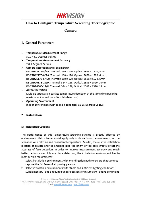
How to Configure Temperature Screening ThermographicCamera1.General ParametersTemperature Measurement Range30.0-45.0 Degrees CelsiusTemperature Measurement Accuracy± 0.5 Degrees CelsiusCamera Resolution and Focal LengthDS-2TD1217B-3/PA: Thermal: 160 × 120, Optical: 2688 × 1520, 3mmDS-2TD1217B-6/PA: Thermal: 160 × 120, Optical: 2688 × 1520, 6mmDS-2TD2617B-6/PA: Thermal: 160 × 120, Optical: 2688 × 1520, 6mmDS-2TD2637B-10/P: Thermal: 384 × 288, Optical: 2688 × 1520, 10mmDS-2TD2636B-15/P: Thermal: 384 × 288, Optical: 2688 × 1520, 15mmAI Face DetectionMultiple targets skin-surface temperature detection at the same time (wearing masks or not would not affect this detection)Operating EnvironmentIndoor environment with calm air condition; 10-35 Degrees Celsius2.Installation1)Installation CautionsThe performance of this Temperature-screening scheme is greatly affected by environment. This scheme would apply only to those indoor environments, or the scenarios with calm air and consistent temperature. Besides, the relative installation location of devices and the ambient light (too bright or too dark) greatly affect the accuracy of face detection. In order to improve measurement accuracy and reach better performance of human face detection, the installation environment has to meet certain requirements:1. Select installation environments with one-direction path to ensure that camerascapture the full faces of all passing persons.2. Select installation environments with stable and sufficient lighting conditions.Supplementary light is required under backlight or insufficient lighting conditions © Hangzhou Hikvision Digital Technology Co.,Ltd. All Rights Reserved.to ensure the clear visibility of facial features.3. Select indoor environments with calm air and consistent temperature condition.Outdoor environments with rapid temperature changes are not recommended.4. If this scheme is used in entrance scenes that connect indoors and outdoorsenvironments, It is suggested that the installation location should be kept at a certain distance from the entrance (such as customs or security checkpoints).5. Avoid objects with high or low temperature placed in the scene.6. The devices should be installed firmly, thereby avoiding face detection andtemperature measurement errors caused by shaking.7. Skin-surface temperature can be affected by environment temperature, if it’s toohot and cold in outdoor environment, we recommend people to stay indoor for more than 3 minutes before temperature measurement.2)Camera InstallationThe camera should be set right in front of the one-direction path, capturing the full faces of passing persons. The installation height and the distance between the camera and measured objects is depended on the resolution and focallength of thermographic camera, as shown in the following table.There are tripods, tripod adapters, wall mount offered by HIKVISION for flexible or fixed placement, but these items require additional purchase. Only device with resolution of 384*288 is recommended to be installed on the wall.© Hangzhou Hikvision Digital Technology Co.,Ltd. All Rights Reserved.© Hangzhou Hikvision Digital Technology Co.,Ltd. All Rights Reserved.3. Configuration1) Select VCA Resource TypeSteps:1. Enter VCA Resource Type interface: Configuration > System>Maintenance>VCA Resource Type .2. Select Temperature Screening as VCA Resource Type.3. Click Save and wait for device restart.© Hangzhou Hikvision Digital Technology Co.,Ltd. All Rights Reserved.2) Set Local ConfigurationSteps:1. Go to the Local Configuration interface: Configuration > Local .2. Click to enable the following settings:Rules: It refers to the rules on your local browser; select Enable to displaybounding boxes and temperature information when the face target is detected. Display Rules Info. on Capture: Select Yes Display rules information on thecapture.Display Temperature Info.: Select Yes to display temperature information withtemperature measurement rule configured.Display Temperature Info. on Capture: Select Yes to display temperatureinformation on the capture. 3. Click Save .© Hangzhou Hikvision Digital Technology Co.,Ltd. All Rights Reserved.3) Settings of Temperature ScreeningSteps:1. Go to the Temperature Screening Settings interface: Temperature Screening > Basic Settings.2. Configure the following settings:Enable Temperature Measurement: Check this box to enable temperaturemeasurement.Display Temperature Info. on Stream: Check this box to display temperatureinformation on stream.Emissivity: The relative ability of material surface to emit energy by radiation.For human skin, this value is normally set as 0.98. Distance Mode:Set mode as ‘Self Adaption’.Distance: The actual distance between the camera and measured object. 3. Click Save .4.Go to the Temperature Screening Settings interface: Temperature Screening >Temperature Screening Configuration5.Select the optical camera channel (normally as Camera 01).6.Configure the following settings:Enable Face Detection: Check this box to enable face detection function.Display Temperature: Check this box to display measured temperature.Upload Captured Face Image: Check this box to upload captured face image.Display Face Temperature Position: Check this box to display the point with highest temperature in target frame.Configuration: Select as Targeting.Face Detection Parameters:●Set Generation Speed and Sensitivity both as 5 for best detectionperformance.●It is suggested to set Alarm When Temperature is above as 37.5 degreesCelsius and Pre-Alarm Temperature as 37 degrees Celsius, or it could beadjusted to meet other requirements.Draw Area: Draw a rectangular area; only objects in this area would be detected as targets for temperature measurement.Press Max. Pupil Distance and Min. Pupil Distance to draw width filter frame, thereby preventing false alarm caused by people’s being too close or too far. This pupil filter is actually based on the pixel width of target frame.7.Click Save.© Hangzhou Hikvision Digital Technology Co.,Ltd. All Rights Reserved.8.Select the thermal camera channel (normally as Camera 02).9.Configure the following settings:Black Body Parameters: If no blackbody is used in this scheme, uncheck this box. Body Temperature Compensation: Compensate the measured value according to the real-time environment temperature.●Enable:Check this box to enable body temperature compensation●Compensation Type: Setting as Auto is suggested; in this way, autocompensation and manual calibration value would both added to themeasured value.●Manual Calibration: The set value would be added to the measured value.(If this value is set as 2 degrees Celsius and the measured value is 35 degreesCelsius, the displayed value would be 37 degrees Celsius). See ManualCalibration part in below for details.●Environment Temperature: Setting as Auto is suggested; in this way, theenvironment temperature would be automatically measured.10.Click Save.4)Manual CalibrationPurpose:© Hangzhou Hikvision Digital Technology Co.,Ltd. All Rights Reserved.The performance of this body thermography scheme offered by HIKVISION would be affected by different actual working environments, and the affect factors in most stable environments could be regarded as a kind of system error. If needed, it is suggested to make a compensation through the manual calibration, the steps are as following.Steps:1.Device start-up; wait a period of time (more than 60 minutes) for preheating.2.For 5 to 10 individuals, complete the following 3 steps one by one:Use the ear thermometer or other specialized thermometer to get the real body temperature, and record.Use the thermographic camera to get the body temperature of the same individual, and record.Subtract these two numbers, and record the difference value.3.Set Manual Calibration with the average value of these difference values in BodyTemperature Compensation.For example:If data recorded during the calibration process are as the following table,thereby setting the Manual Calibration as 0.5 degrees Celsius.4.Other Notes for UseBefore the device is used in actual body temperature measurement, it should run for more than 60 minutes for preheating.This product is used for preliminary screening of people with Temperature. After alarm happens, specialized medical thermometer should be used in further body temperature check.© Hangzhou Hikvision Digital Technology Co.,Ltd. All Rights Reserved.First Choice for Security Professionals HIK VISION Technical Support© Hangzhou Hikvision Digital Technology Co.,Ltd. All Rights Reserved.。
海康威视简易说明书完整版

海康威视简易说明书 HUA system office room 【HUA16H-TTMS2A-HUAS8Q8-HUAH1688】海康威视iVMS-4200操作说明书前言非常感谢您购买我公司的产品,如果您有什么疑问或需要请随时联系我们。
适用型号本手册适用于网络视频监控软件iVMS-4200。
声明本手册可能包含技术上不准确的地方,或与产品功能及操作不相符的地方,或印刷错误。
我司将根据产品功能的增强或变化而更新本手册的内容,并将定期改进及更新本手册中描述的软硬件产品。
更新的内容将会在本手册的新版本中加入,恕不另行通知。
本手册中内容仅为用户提供参考指导作用,不保证与实物完全一致,请以实物为准。
约定在本手册中为了简化描述,做以下约定:网络视频监控软件iVMS-4200简称为软件。
网络硬盘录像机、、视频服务器、NVR、IP Camera和IP Dome等统一称为设备。
. iVMS-4200 简介. 功能概述软件iVMS-4200是为嵌入式网络监控设备开发的软件应用程序,适用于嵌入式网络硬盘录像机、混合型网络硬盘录像机、网络视频服务器、NVR、IP Camera、IP Dome、PCNVR和解码设备以及视音频编解码卡,支持实时预览、远程配置设备参数、录像存储、远程回放和下载等多种功能。
iVMS-4200具有以下特点:界面容器化处理模式:在客户端组件的界面设计上,精心采用容器化处理,简化了多屏和单屏切换的处理方式,大幅改善多屏操作感受,适应了一机多屏的PC发展趋势。
通道化管理模式:在客户端组件设计中,加入了通道化管理模式,抛开了以设备为核心主体的传统设计方式,更加适应于IP监控的发展方向。
用户体验为重心的界面设计:提供图片式可视化控制面板,以用户体验为重心,颠覆式的采用所需即可用的模式,提供一个功能的多个入口,以期达到最大限度减少用户操作步骤的目标。
需要才可见的显示方式:在客户端组件的界面元素上,加入了需要才可见的显示方式,在日历,时间条,工具栏,系统信息栏等多处,加入该设计模式,最大限度的节省有限的屏幕显示空间。
海康电子警察用户手册簿

iVMS-8620闯红灯自动记录系统使用说明书声明iVMS-8620闯红灯自动记录系统是由海康威视自主开发的专用道路监控系统,其受中华人民国法保护。
海康威视拥有本文的全部,未经本公司许可,任何单位及个人不得对本文中的任何部分进行转印、影印或复印。
信息反馈海康威视尽最大的努力保证本手册的准确性和完整性。
如果您在使用中发现问题,希望及时将情况反馈给我们以完善产品,我们将非常感您的支持。
总公司联系方式公司总机:08技术支持:400 700 5998传真:03地址:中国马塍路36号邮编:310012公司E-mail:Hkvshikvision.公司:.hikvision.目录第1章概述 (4)第2章运行环境要求 (5)第3章基本操作 (6)3.1管理中心 (6)3.2报警服务器 (9)3.3 C/S客户端基本操作 (12)3.3.1系统管理 (14)3.3.2布控管理 (37)3.3.3路口监控 (46)3.3.4实时地图预览 (51)3.3.5数据查询 (58)3.3.6统计分析 (71)3.4 Web客户端操作 (82)3.4.1登录Web客户端 (82)3.4.2实时过车监控 (83)3.4.3数据查询 (83)3.4.4统计分析 (85)3.4.5系统管理 (86)3.4.6布控管理 (87)附录1 数据库安装 (88)Oracle数据库客户端的安装与配置 (88)第1章概述iVMS-8620闯红灯自动记录系统在指定的路段安装数据采集设备,通过各级接入服务器,最终实现对交通车辆的有效查控作用。
软件平台包括管理中心、报警服务器、数据库服务器、备份服务器、查询客户端、WEB服务器、VRM服务器以及路口前端进行数据采集、处理、发送的道口管理主机,可实现对通过路口车辆的测速、牌照识别、车型识别、超速报警、布控、网络查询统计等功能。
iVMS-8620闯红灯自动记录系统拓扑图如下所示:DVR存储第2章运行环境要求硬件环境(服务器参考配置):1*Xeon E5620-2.4G(四核12M/5.86GT/s)2*2GB DDR3 ECC/2*146G(SAS/15Krpm/3.5英寸)2*1000M NIC冗余电源软件环境:Windows Server 2003R2 Edition sp2 32位系统、Server 2008 64位系统Oracle 10.2.0.1.0 版本数据库网络环境:具有足够的带宽,支持各种多媒体业务和确保实时处理;可靠的网络结构,支持系统不间断运行;网络具有开放性,采用标准的接口方式;网络具有较好的可扩性,方便将来各系统扩展;具有很强的网络管理能力,便于网络维护、运行管理和网络安全。
- 1、下载文档前请自行甄别文档内容的完整性,平台不提供额外的编辑、内容补充、找答案等附加服务。
- 2、"仅部分预览"的文档,不可在线预览部分如存在完整性等问题,可反馈申请退款(可完整预览的文档不适用该条件!)。
- 3、如文档侵犯您的权益,请联系客服反馈,我们会尽快为您处理(人工客服工作时间:9:00-18:30)。
iVMS-8620闯红灯自动记录系统使用说明书版权声明iVMS-8620闯红灯自动记录系统是由海康威视自主开发的专用道路监控系统,其版权受中华人民共和国版权法保护。
海康威视拥有本文的全部版权,未经本公司许可,任何单位及个人不得对本文中的任何部分进行转印、影印或复印。
信息反馈海康威视尽最大的努力保证本手册的准确性和完整性。
如果您在使用中发现问题,希望及时将情况反馈给我们以完善产品,我们将非常感谢您的支持。
总公司联系方式公司总机:8技术支持电话:400 700 5998传真:3地址:中国杭州马塍路36号邮编:310012公司E-mail:公司网站:目录第1章概述 (4)第2章运行环境要求 (5)第3章基本操作 (6)3.1管理中心 (6)3.2报警服务器 (9)3.3 C/S客户端基本操作 (12)3.3.1系统管理 (14)3.3.2布控管理 (37)3.3.3路口监控 (46)3.3.4实时地图预览 (51)3.3.5数据查询 (58)3.3.6统计分析 (71)3.4 Web客户端操作 (82)3.4.1登录Web客户端 (82)3.4.2实时过车监控 (83)3.4.3数据查询 (84)3.4.4统计分析 (85)3.4.5系统管理 (86)3.4.6布控管理 (87)附录1 数据库安装 (88)Oracle数据库客户端的安装与配置 (88)第1章概述第1章iVMS-8620闯红灯自动记录系统在指定的路段安装数据采集设备,通过各级接入服务器,最终实现对交通违法车辆的有效查控作用。
软件平台包括管理中心、报警服务器、数据库服务器、备份服务器、查询客户端、WEB服务器、VRM服务器以及路口前端进行数据采集、处理、发送的道口管理主机,可实现对通过路口车辆的测速、牌照识别、车型识别、超速报警、布控、网络查询统计等功能。
iVMS-8620闯红灯自动记录系统拓扑图如下所示:第2章运行环境要求硬件环境(服务器参考配置):1*Xeon E5620-2.4G(四核12M/5.86GT/s)2*2GB DDR3 ECC/2*146G(SAS/15Krpm/3.5英寸)2*1000M NIC冗余电源软件环境:Windows Server 2003R2 Edition sp2 32位系统、Server 2008 64位系统Oracle 版本数据库网络环境:具有足够的带宽,支持各种多媒体业务和确保实时处理;可靠的网络结构,支持系统不间断运行;网络具有开放性,采用标准的接口方式;网络具有较好的可扩性,方便将来各系统扩展;具有很强的网络管理能力,便于网络维护、运行管理和网络安全。
第3章基本操作3.1管理中心管理中心主要为平台其他模块提供验证服务,获取前端设备单元的运行状态等。
具体功能如下:1)连接验证:客户端登陆成功后要定时与管理中心进行连接验证;2)加密狗验证:带有加密狗的正式版本,在使用时都要向管理中心进行加密狗信息验证;3)设备状态监测:包括\道口主机、高清摄像机、车检器、线圈等的运行状态;4)日常信息维护:按照设定的维护时间,定期对过车信息、报警信息、日志信息等进行维护;5)校时功能:管理中心按照校时周期主动向道口主机发送校时命令;管理中心定时对分析仪服务器、VRM服务器、PCNVR服务器校时;运行管理中心,进入管理中心。
管理中心包括查看、路口状态和关于三部分。
查看点击管理中心左侧的按钮,可查看管理中心的即时信息,如下图所示。
路口状态点击管理中心左侧的按钮,可查看系统内各路口的状态,如下图所示。
在路口图标上点击鼠标右键,可查看该路口的各前端设备的详细运行状态,包括前端的道口主机、硬盘、摄像机、车检器及线圈的状态,如下图所示关于点击管理中心左侧的按钮,可查看管理中心以及相关动态链接库的版本信息,如下图所示。
3.2报警服务器如拓扑结构图所示,报警服务器是连接前端和后端平台业务的桥梁。
它主要负责实时过车数据的解析、接收、存储、转发,以及报警功能。
具体功能如下:1)接收前端道口主机的过车信息和高清图片。
2)识别超速车辆,生成违章信息。
3)通过比对布控车辆库,实现对布控车辆包括黑名单、红名单及各类违章车辆的识别,生成报警信息上传中心。
4)在数据库服务器中写入正常过车及布控、违章车辆信息。
5)上传图片至图片服务器进行存储。
6)给C/S客户端和WEB客户端发送正常过车、超速过车、布控过车的车辆信息,及相应的过车图片。
运行报警服务器,进入报警服务器。
报警服务器包括查看、配置和关于三部分。
查看点击报警服务器左侧的按钮,可查看即时信息,如下图所示。
点击按钮,可查看已添加的路口信息,如下图所示:配置点击报警服务器左侧的按钮,可对报警服务器进行相应配置:过车图片保存天数、缓存图片的存储路径以及是否启动系统看门狗等设置,如下图所示。
注:报警服务器磁盘选择为本地缓存磁盘,应与图片服务器的存储磁盘区分开,否则起不到缓存的效果。
关于点击报警服务器左侧的按钮,可查看报警服务器以及相关动态链接库的版本信息,如下图所示。
3.3C/S客户端基本操作C/S客户端主要负责整个平台的系统配置和业务功能,接收报警服务器上传的实时过车信息,查看前端设备单元的运行状态等。
具体功能如下:1)配置组织机构、路口、车道、用户等资源信息。
2)监测前端设备,包括道口主机、高清摄像机、车检器、线圈等的运行状态。
3)接收单路口实时过车图片。
4)接收所有路口的正常过车、超速过车、布控过车等信息。
5)实现机动车、非机动车、违章过车、异常牌照等信息的查询和图片校对下载功能。
6)实现多种模式的车流统计功能,各种车辆信息的分析功能,电子地图功能。
运行C/S客户端,进入登录界面,如下图所示。
注:1. 初次登录CS客户端的默认用户名/密码为:admin/12345,登录客户端可修改密码;2. 运行C/S客户端时必须先开启管理中心,以进行用户验证操作;输入用户名和密码,点击“登录”按钮进行登录。
可勾选“自动登录”选项,以后登录就不会提示输入用户名和密码直接登录。
若修改登录用户的密码,可点击“修改密码”按钮,修改密码界面如下。
输入旧密码后,可以更改新的用户密码,点击“提交”按钮进行修改。
用户登录后,进入C/S客户端主界面。
C/S客户端界面说明如下:区域说明区域说明系统功能按键区域路口实时过车图片显示区域过车信息、运行状态显示区域路口、车道显示列表道路示意图显示区3.3.1系统管理登录C/S客户端后,首先需要对系统内的组织机构、路口、用户等信息进行配置。
点击左侧“系统管理”显示系统配置菜单。
组织资源:对路口、设备、报警服务器和存储服务器等资源进行管理。
用户管理:可进行用户操作和角色操作:用户是用来登录C/S客户端或B/S客户端的;角色用来指定用户的权限。
自定义设置:对一些特殊的案例,可以自定义设置相应的报警、布控类型。
地图设置:对地图进行配置,并可与路口进行关联。
录像计划配置:对已添加的DS-9000DVR设备、全景相机进行录像计划的配置。
区间测速设置:根据区间起始和终止路口之间的距离,依据不同类型车辆的最高和最低时速,计算出经过该区间的最长行驶时间和最短行驶时间。
车辆经过该区间的行车时间若不在时间范围内则进行报警操作。
报警声音设置:针对不同的报警和布控类型,可设置不同的报警声音。
短信报警设置:短信报警需接入第三方短信平台,当出现报警时,会短信通知事先配置的人员。
系统参数:主要包括日志保存天数、自动登录客户端等设置。
3.3.1.1组织资源在“系统管理”菜单中点击,进入组织资源界面,可对组织资源进行管理操作。
点击左侧组织结构栏中的按钮,可添加组织机构。
组织信息包括上级组织、组织编号和组织名称。
点击按钮可修改组织编号和组织名称。
点击按钮可删除选定组织及该组织的下属资源。
路口管理点击资源内的 按钮,进入路口管理列表。
点击上方的按钮可添加路口。
路口添加信息说明如下:路口信息 说明所属报警服务器所添加的路口所属的报警服务器 路口编号 系统中需设置该路口的编号路口名称 系统中路口的名称 IP 地址 路口中道口主机的IP 地址 端口号 路口中道口主机的端口号路口类型 道口主机的类型车道数 该路口所包含的车道数目(可自定义车道数量和方向名称)图片路径 添加路口图片显示的本地路径标识限速 通过该路口的限速信息 执法限速 通过该路口的执法限速信息 保养期至该路口下次保养的时间选择已添加的路口,点击 按钮可删除该路口;点击按钮可修改该路口配置信息。
注:添加的路口默认在当前选中的组织下,添加前应选择好对应的组织。
相机管理点击资源内的按钮,进行相机管理配置。
注:在进行过“DVR 设置”,即添加过DVR 设备后才可以在“相机管理”中进行“启用视频通道”配置 选择需配置的车道,进行车道信息的配置。
可配置该车道的名称和抓拍相机的IP 地址与端口号; 勾选“启用视频通道”选项,可启用该车道查看实时录像:选择对应的摄像机并设置通道名称; 完成修改后,点击“保存”按键保存设置。
相机管理(直连抓拍机版本)直连抓拍机版本即前端没有道口主机,闯红灯自动记录系统直接连接抓拍相机。
直连抓拍机版本的其他操作和配置无异,只有相机管理中稍有不同。
点击资源内的按钮,进行相机管理配置。
注:1.在进行过“DVR 设置”,即添加过DVR 设备后才可以在“相机管理”中进行“启用视频通道”配置; 2.在一个抓拍机对应多个车道的实际项目中,对应的多个车道可配置同一个抓拍机。
设备管理 点击资源内的 按钮,进入设备管理列表。
点击上方的按钮可添加设备。
设备添加信息说明如下:设备信息 说明设备类型 所添加的设备类型,包括DS-9000和其他设备设备名称 添加的设备的名称 通道数 添加设备的通道数 IP 地址 添加的设备的IP 地址 端口号 添加的设备的端口号 用户名 登陆设备的用户名 密码 登录设备的密码 通道名称添加的设备各通道的名称选择已添加的设备,点击 按钮可删除该设备;点击按钮可修改该设备的配置信息。
注:添加的设备默认在当前选中的组织下,添加前应选择好对应的组织。
报警服务器点击资源内的 按钮,进入报警服务器列表。
点击上方的按钮可添加报警服务器。
报警服务器添加信息说明如下:报警服务器信息 说明报警服务器名称 所添加的报警服务器名称 报警服务器IP 添加的报警服务器的IP 地址 报警服务器端口号 添加报警服务器的端口号 图片服务器名称该报警服务器对应的图片服务器选择需配置的车道,进行车道信息的配置。
这里除了要配置车道对应抓拍机的IP 地址和端口号之外,还要设置登录抓拍机的用户名和密码,以及抓拍机关联车道所对应的方向。
勾选“启用视频通道”选项,可启用该车道查看实时录像:选择对应的摄像机并设置通道名称; 完成修改后,点击“保存”按键保存设置。