HTB-48I4中文资料
Autodesk Nastran 2023 参考手册说明书
FILESPEC ............................................................................................................................................................ 13
DISPFILE ............................................................................................................................................................. 11
File Management Directives – Output File Specifications: .............................................................................. 5
BULKDATAFILE .................................................................................................................................................... 7
T482 规格书
4/12
EAC3
AAC, HEAAC WMA LPCM IMA-ADPCM/MS-ADPCM LBR
N/A(work with video files only)
M4A/AAC WMA/ASF N/A(work with video files only) N/A(work with video files only) N/A(work with video files only)
dat, mpg, MPG,MPEG mpeg
Mpeg1,2
1920x1080@ 30P 20Mbit/sec
ts, trp, tp, MPEG2 -TS
m2ts
H264-TS
MPEG2 ,H.264
1920x1080 @ 30P 20Mbit/sec
vob
MPEG2 -PS MPEG2
1920x1080 @ 30P 20Mbit/sec
15360x8640 1024x768 9600x6400 1200x800 9600x6400
Required DRAM size by T3/T4 (Mbytes) 3.96 6.00 3.66 3.66 3.66
5/12
外观说明 PAL/SECAM/BG,DK,I 的板的外形
3
6
14
13
7
8
输入/出接口:TVx1、AVx2、S-VIDEOx1、HDMIx2、VGAx1、YPBPRx2,AV-OUTx1,USBx1; 扩展接口有 DVD 接口,可外接 1 路 AV 接口;使用外接 AV 时,后端子的 AV1 将变为同轴输出; 两路高清多媒体播放 USB 接口,其中一路扩展;支持 H.264 编码格式; 输出格式:单/双路 8/10bit 的 LVDS 屏;加 120Hz 转接板可扩展屏接口; 内置 2 路 HDMI 接口; 视频信号格式 PAL、NTSC、SECAM 自动检测;全 3D Interlace, 3D 视频解码处理; 高清 RGB/YPBPR/YCBCR 信号输入最大支持 1080P; 内置音效处理,音量、静音、高音、低音、平衡、EQ 功能;支持丽音,VPS、CC、VHIP 功能(可选); 全制式 TV 信号接收, 200 频道存储,支持频道自动排序功能; 数字音频功放,最大输出功率 2 X 8W(8 欧); 扩展功能丰富:预留了数字电视、读卡及 DVD 模块的接口,方便进行功能扩展; 多国语言 OSD 菜单;
超低电压大电流直流电子负载

1.2.
主要特点 ............................................................................................................ 1
1.3.
主机面板介绍 .................................................................................................... 2
2.6.2. 控制连接 ............................................................................................................ 6
2.6.3. 采样连接 ............................................................................................................ 6
3.1.
控制模式 ............................................................................................................ 8
3.2.
恒电流测试功能(CC) ................................................................................... 8
2.6.
连接方式 ............................................................................................................ 5
HTB-48I2中文资料

Description• For 1/4" x 1-1/4" and 5mm x 20mm fuses • All holder bodies have the option of using 1/4" x 1-1/4" or 5mm x 20mm carriers• Withstands 15 to 20 lbs-in torque to mounting nut when mounting fuseholder to panel • High temperature, flame retardant, Thermoplastic meets UL 94 VOAgency Information• UL Recognized:IZL T2, E14853• CSA Component Acceptance:Class 6225-01, File 47235FuseholdersHTB Panel Mount SeriesReplacement PartsMaximum Panel ThicknessBody TypeInch MillimetersHTB-20.307.62HTB-30.307.62HTB-40.125 3.18HTB-50.125 3.18HTB-60.307.62HTB-80.125 3.18HTB-90.1253.18SPECIFICATIONSProduct Current Voltage Fuse Quick Code Rating Rating Size Connect HTB-X2I 15A 250V 1/4" x 1-1/4"3/16"HTB-X4I 15A 250V 1/4" x 1-1/4"3/16"HTB-X6I 20A 250V 1/4" x 1-1/4"1/4"HTB-X8I 20A 250V 1/4" x 1-1/4"1/4"HTB-X2M 15A 250V 5mm x 20mm 3/16"HTB-X4M 15A 250V 5mm x 20mm 3/16"HTB-X6M 16A 250V 5mm x 20mm 1/4"HTB-X8M 16A250V5mm x 20mm 1/4"FuseholdersHTB Panel Mount SeriesVisit us on the Web at 3601 Quantum Boulevard Boynton Beach, Florida 33426-8638T el:+1-561-752-5000 T oll Free:+1-888-414-2645 Fax:+1-561-742-1178This bulletin is intended to present product design solutions and technical information that will help the end user with design applications. Cooper Electronic Technologies reserves the right, without notice, to change design or construction of any products and to discontinue or limit distribution of any products. Cooper Electronic Technologies also reserves the right to change or update, without notice, any technical information contained in this bulletin. Once a product has been selected, it should be tested by the user in all possible applications.OC-2580 5/02© Cooper Electronic Technologies 2002PACKAGING CODEPackaging CodeDescriptionBlank 10 pieces of fuseholders packed into a cartonBK100 pieces of fuseholders packed into a cardboard shelf package。
HUNTERI4 系列变频器 用户操作手册说明书

HUNTERI4系列变频器用户操作手册简易版(V1.3)前 言感谢您使用宁波弘讯科技股份有限公司的高性能矢量变频器!HUNTERI4系列变频器是一款通用高性能矢量系统型变频器,具备低频力矩大、电机参数自辨识、最优加减速控制、逐波限流等先进的控制性能;具备强大I/O扩展功能,支持多种通讯扩展卡,可以为客户定制工艺控制卡等扩展能力;具备满足不同工艺要求的功能,如多段速控制、简易PLC控制、闭环控制、定长控制、下垂控制、自动节能运行、灵活的频率给定方式,多样的频率组合方式以及组合算法等一系列实用的功能。
可用于机床、线缆、纺织、造纸、食品、包装、化工、市政工程等自动化生产设备的驱动,满足不同工业设备对性能、功能的需求。
在使用HUNRERI4变频器之前,请变频器使用者及相关技术人员仔细阅读本手册,以确保能正确安装和操作变频器,使变频器发挥其最佳性能。
本用户手册如有改动,请以新版为准,恕不另行通知。
高性能矢量系统型变频器用户手册资料版本:V1.3本产品执行标准:本产品的设计、生产制造参照了最新版本的国家标准(GB或GB/T)及国际电工委员会标准(IEC)及国际单位制(SI),其相关部分技术参数可以满足的国家标准(GB或GB/T)及国际电工委员会标准(IEC)标准要求。
主要依据标准:GB/T 12668.2-2002 调速电气传动系统第2部分一般要求----低压交流变频电气传动系统额定值的规定GB 12668.3-2012 调速电气传动系统第3部分----产品电磁兼容性标准及其特定的试验方法GB 12668.501-2013调速电气传动系统第5部分安全要求电气、热和能量GB/T 2423.1-2008 电工电子产品环境试验第1部分----试验方法试验A: 低温GB/T 2423.2-2008 电工电子产品环境试验第2部分----试验方法试验B: 高温GB/T 2423.3-2006 电工电子产品环境试验规程试验Ca----恒定湿热试验方法GB/T 2423.4-2008 电工电子产品环境试验规程试验Db----交变湿热试验方法GB/T 2423.9-2006 电工电子产品环境试验第9部分----试验方法试验Cb: 设备用恒定湿热GB/T 2423.7-1995 电工电子产品环境试验第7部分----试验方法试验Ed:自由跌落GB/T 2423.22-2012 电工电子产品环境试验规程试验N----温度变化试验方法GB/T4798.1-2005 电工电子产品应用环境条件储存GB/T4798.2-2008 电工电子产品应用环境条件运输III读者对象本用户操作手册适合以下人员阅读变频器安装人员、工程技术人员(电气工程师、电气操作工等)、设计人员等请确保此用户手册到达最终用户手中。
华大驱动器说明书-中文

1.5 技术规格................................................................................................................................. 7
1.5.1
通用规格 ......................................................... 7
● 其他
· 绝对不要自行改造伺服驱动器。
注意
3
SAF
· 目录
第 1 章 型号与规格 .................................................................................................................... 6
2.4 标准连接............................................................................................................................... 11
2.4.1
电源端子 ........................................................ 11
● 防止火灾
注意
· 不要将伺服驱动器、伺服电机以及制动电阻安放在易燃物质上或靠近易燃物质。 · 不要将伺服驱动器暴露在有水气、腐蚀性气体、可燃性气体的物质的场所下使用,否则可能导致火灾。 · 当使用制动电阻时,如果出现错误的信号,请切断主电源。否则,制动电阻故障或类似故障可能使制动
HT48CA5资料

HT48RA5/HT48CA5Remote Type 8-Bit MCURev.1.201June 10,2005General DescriptionThe HT48RA5/HT48CA5are 8-bit high performance,RISC architecture microcontroller devices specifically designed for multiple I/O control product applications.The data ROM can be used to store remote control codes.The mask version HT48CA5is fully pin and func-tionally compatible with the OTP version HT48RA5de-vice.The advantages of low power consumption,I/O flexibil-ity,timer functions,oscillator options,watchdog timer,programmable frequency divider,HALT and wake-up functions,as well as low cost,enhance the versatility of these devices to suit a wide range of application possi-bilities such as industrial control,consumer products,subsystem controllers,and particularly suitable for use in products such as universal remote controller (URC).Features·Operating voltage:2.0V~5.5V ·23bidirectional I/O lines (max.)·1interrupt input shared with an I/O line ·8-bit programmable timer/event counter withoverflow interrupt and 8-stage prescaler (TMR0)·16-bit programmable timer/event counter andoverflow interrupts (TMR1)·On-chip crystal and RC oscillator ·Watchdog Timer·40K ´16program memory (8K ´16bits ´5banks)·224´8data memory RAM ·PFD supported·HALT function and wake-up feature reduce powerconsumption·8-level subroutine nesting·Up to 1m s instruction cycle with 4MHz system clock atV DD =3V·Bit manipulation instruction ·16-bit table read instruction ·63powerful instructions·All instructions in one or two machine cycles ·Low voltage reset function·28-pin SOP/SSOP (209mil)packageTechnical Document·Tools Information ·FAQs·Application Note-HA0016E Writing and Reading to the HT24EEPROM with the HT48MCU Series -HA0018E Controlling the HT1621LCD Controller with the HT48MCU Series -HA0041E Using the HT48CA0to Generate the HT6221Output Signals -HA0075E MCU Reset and Oscillator Circuits Application Note -HA0076E HT48RAx/HT48CAx Software Application Note-HA0082E HT48xA0-1and HT48xA0-2Power-on Reset TimingBlock DiagramPin AssignmentRev.1.202June10,2005Pin DescriptionPin Name I/O ROM CodeOptionDescriptionPA0~PA7I/OWake-up*Pull-high***Bidirectional8-bit input/output port.Each bit can be configured as a wake-up in-put by a option.Software instructions determine the CMOS output or Schmitt trig-ger input with/without pull-high resistor.The pull-high resistor of each input/outputline is also optional.PB0/PFD PB1~PB7I/OPull-high**PB0or PFDBidirectional8-bit input/output port.Software instructions determine the CMOSoutput or Schmitt trigger input with/without pull-high resistor.The pull-high resis-tor of each input/output line is also optional.The output mode of PB0can beused as an internal PFD signal output and it can be used as a various frequencycarrier signal.PC0/TMR0PC1~PC4 PC5/TMR1I/O Pull-high*Bidirectional6-bit input/output port.Software instructions determine the CMOSoutput or Schmitt trigger input with/without pull-high resistor.The pull-high resis-tor of each input/output line is also optional.PC0and PC5are pin shared withTMR0and TMR1function pins.PF0/INT I/O Pull-high*Bidirectional1-bit input/output port.Software instructions determine the CMOS output or Schmitt trigger input with/without pull-high resistor.The pull-high resis-tor of this input/output line is also optional.PF0is pin shared with the INT func-tion pin.OSC1 OSC2IOCrystalor RCOSC1,OSC2are connected to an RC network or Crystal(determined by option)for the internal system clock.In the case of RC operation,OSC2is the outputterminal for1/4system clock.RES I¾Schmitt trigger reset input,active low.VSS¾¾Negative power supply,groundVDD¾¾Positive power supplyNote:*Bit option**Nibble option***Byte optionAbsolute Maximum RatingsSupply Voltage...........................V SS-0.3V to V SS+6.0V Storage Temperature............................-50°C to125°C Input Voltage..............................V SS-0.3V to V DD+0.3V Operating Temperature...........................-40°C to85°C Note:These are stress ratings only.Stresses exceeding the range specified under²Absolute Maximum Ratings²may cause substantial damage to the device.Functional operation of this device at other conditions beyond those listed in the specification is not implied and prolonged exposure to extreme conditions may affect device reliabil-ity.Rev.1.203June10,2005Symbol ParameterTest ConditionsMin.Typ.Max.Unit V DD ConditionsV DD Operating Voltage¾¾ 2.0¾ 5.5VI DD1Operating Current 3VNo load,f SYS=4MHz¾0.6 1.5mA 5V¾24mAI DD2Operating Current(Crystal OSC,RC OSC)5V No load,f SYS=8MHz¾48mAI STB1Standby Current(WDT Enabled andWDT RC OSC On)3VNo load,system HALT¾ 1.15m A 5V¾410m AI STB2Standby Current(WDT Disabled)3VNo load,system HALT¾0.11m A 5V¾0.22m AV IL1Input Low Voltage for I/O Ports¾¾0¾0.3V DD V V IH1Input High Voltage for I/O Ports¾¾0.7V DD¾V DD V V IL2Input Low Voltage(RES)¾¾0¾0.4V DD V V IH2Input High Voltage(RES)¾¾0.9V DD¾V DD VV LVR Low Voltage Reset¾LVR=2.0V 1.8 1.9 2.0V LVR=3.0V 2.7 3.0 3.3VI OL I/O Port Sink Current 3VV OL=0.1V DD48¾mA 5V1020¾mAI OH I/O Port Source Current 3VV OH=0.9V DD-2-4¾mA 5V-5-10¾mAR PH Pull-high Resistance 3V¾2060100k W 5V103050k WRev.1.204June10,2005Symbol ParameterTest ConditionsMin.Typ.Max.Unit V DD Conditionsf SYS1System Clock(Crystal OSC)¾ 2.0V~5.5V400¾4000kHz ¾ 3.3V~5.5V400¾8000kHzf SYS2System Clock(RC OSC)¾ 2.0V~5.5V400¾4000kHz ¾ 3.3V~5.5V400¾8000kHzf TIMER Timer I/P Frequency(TMR0/TMR1)3V50%duty0¾4000kHz 5V0¾8000kHzt WDTOSC Watchdog Oscillator Period 3V¾4590180m s 5V3265130m st WDT1Watchdog Time-out Period(WDT OSC)3VWithout WDT prescaler112346ms 5V81733mst WDT2Watchdog Time-out Period(f SYS/4)¾Without WDT prescaler¾1024¾t SYS t RES External Reset Low Pulse Width¾¾1¾¾m st SST System Start-up Timer Period¾Power-up reset orwake-up from HALT¾1024¾t SYS t LVR Low Voltage Width to Reset¾¾1¾¾mst INT Interrupt Pulse Width¾¾1¾¾m st ACC Data ROM Access Time¾¾1¾¾m s Note:t SYS=1/(f SYS)Rev.1.205June10,2005Functional DescriptionExecution FlowThe system clock for the MCU is derived from either a crystal or an RC oscillator.The system clock is internally divided into four non-overlapping clocks.One instruc-tion cycle consists of four system clock cycles.Instruction fetching and execution are pipelined in such a way that a fetch takes an instruction cycle while de-coding and execution takes the next instruction cycle. However,the pipelining scheme causes each instruc-tion to effectively execute in a cycle.If an instruction changes the program counter,two cycles are required to complete the instruction.Program Counter-PCThe program counter(PC)controls the sequence in which the instructions stored in the program ROM are executed and its contents specify a full range of pro-gram memory.After accessing a program memory word to fetch an in-struction code,the contents of the program counter are incremented by one.The program counter then points to the memory word containing the next instruction code.When executing a jump instruction,conditional skip ex-ecution,loading register,subroutine call or return from subroutine,initial reset,internal interrupt,external inter-rupt or return from interrupts,the PC manipulates the program transfer by loading the address corresponding to each instruction.The conditional skip is activated by instructions.Once the condition is met,the next instruction,fetched during the current instruction execution,is discarded and a dummy cycle replaces it to get the proper instruction. Otherwise proceed to the next instruction.The lower byte of the program counter(PCL)is a read-able and writeable register(06H).Moving data into the PCL performs a short jump.The destination will be within the current program ROM page.When a control transfer takes place,an additional dummy cycle is required.Execution FlowModeProgram Counter*15~*8*7*6*5*4*3*2*1*0Initial Reset0000000000000000 External Interrupt0000000000000100 Timer/Event Counter0Overflow0000000000001000 Timer/Event Counter1Overflow0000000000001100 Skip*15~*13(*12~*0+2)=(within-current bank)Loading PCL*15~*8@7@6@5@4@3@2@1@0 Jump,Call Branch#15~#8#7#6#5#4#3#2#1#0 Return(RET,RETI)S15~S8S7S6S5S4S3S2S1S0Program CounterNote:*15~*0:Program counter bits S15~S0:Stack register bits#15~#0:Instruction code bits@7~@0:PCL bits1bank:8K wordsRev.1.206June10,2005Program Memory-ROMThe program memory is used to store the program in-structions which are to be executed.It also contains data,table,and interrupt entries,and is organized into 8192´16bits´5banks,addressed by the program coun-ter and table pointer.Certain locations in the program memory are reserved for special usage:·Location000HThis area is reserved for program initialization.After chip reset,the program always begins execution at lo-cation000H.·Location004HThis area is reserved for the external interrupt service program.If the input pin is activated,the interrupt is enabled and the stack is not full,the program begins execution at location004H.·Location008HThis area is reserved for the Timer/Event Counter0in-terrupt service program.If a timer interrupt results from a Timer/Event Counter0overflow,and if the in-terrupt is enabled and the stack is not full,the program begins execution at location008H.·Location00CHThis location is reserved for the Timer/Event Counter 1interrupt service program.If a timer interrupt results from a Timer/Event Counter1overflow,and the inter-rupt is enabled and the stack is not full,the program begins execution at location00CH.·Table locationAny location in the program memory can be used as look-up tables.The instructions²TABRDC[m]²(page specified by TBHP)and²TABRDL[m]²(the last page) transfer the contents of the lower-order byte to the specified data memory,and the higher-order byte to TBLH(08H).The higher-order byte table pointer TBHP(1FH)and lower-order byte table pointer TBLP (07H)are read/write registers,which indicate the table locations.Before accessing the table,the location has to be placed in TBHP and TBLP.The TBLH is read only and cannot be restored.If the main routine and the ISR(interrupt service routine)both employ the ta-ble read instruction,the contents of TBLH in the main routine are likely to be changed by the table read in-struction used in the ISR.Errors are thus brought about.Given this,using the table read instruction in the main routine and the ISR simultaneously should be avoided.However,if the table read instruction has to be applied in both main routine and the ISR,the in-terrupt(s)is supposed to be disabled prior to the table read instruction.It(They)will not be enabled until the TBLH in the main routine has been backup.All table related instructions require2cycles to complete the operation.Stack Register-STACKThis is a special part of the memory which is used to save the contents of the program counter(PC)only.The stack is organized into8levels and is neither part of the data nor part of the program space,and is neither read-able nor writeable.The activated level is indexed by the stack pointer(SP)and is neither readable nor writeable. At a subroutine call or interrupt acknowledge signal,the contents of the program counter are pushed onto the stack.At the end of a subroutine or an interrupt routine, signaled by a return instruction(RET or RETI),the pro-gram counter is restored to its previous value from the stack.After a chip reset,the SP will point to the top of the stack.If the stack is full and a non-masked interrupt takes place,the interrupt request flag will be recorded but the acknowledge signal will be inhibited.When the stack pointer is decremented(by RET or RETI),the interrupt will be serviced.This feature prevents stack overflow al-lowing the programmer to use the structure more easily. In a similar case,if the stack is full and a²CALL²is sub-Program MemoryInstructionTable Location*15~*8*7*6*5*4*3*2*1*0TABRDC[m]TBHP@7@6@5@4@3@2@1@0 TABRDL[m]10011111@7@6@5@4@3@2@1@0Table LocationNote:*15~*0:Table location bits@7~@0:Table pointer bitsRev.1.207June10,2005sequently executed,stack overflow occurs and the first entry will be lost(only the most recent8return ad-dresses are stored).Data Memory-RAMThe data memory is designed with250´8bits.The data memory is divided into two functional groups:special function registers and general purpose data memory (224´8).Most are read/write,but some are read only.The special function registers include the indirect ad-dressing registers(R0;00H,R1;02H),bank pointer (BP;04H),Timer/Event Counter0(TMR0;0DH), Timer/Event Counter0control register(TMR0C;0EH), Timer/Event Counter1higher order byte register (TMR1H;0FH),Timer/Event Counter1lower order byte register(TMR1L;10H),Timer/Event Counter1control register(TMR1C;11H),program counter lower-order byte register(PCL;06H),memory pointer registers (MP0;01H,MP1;03H),accumulator(ACC;05H),table pointer(TBLP;07H,TBHP;1FH),table higher-order byte register(TBLH;08H),status register(STATUS; 0AH),interrupt control register(INTC;0BH),Watchdog Timer option setting register(WDTS;09H),I/O regis-ters(PA;12H,PB;14H,PC;16H,PF;1CH),and I/O con-trol registers(PAC;13H,PBC;15H,PCC;17H, PFC;1DH).The remaining space before the20H is re-served for future expanded usage and reading these locations will get²00H².The general purpose data memory,addressed from20H to FFH,is used for data and control information under instruction commands.All of the data memory areas can handle arithmetic, logic,increment,decrement and rotate operations di-rectly.Except for some dedicated bits,each bit in the data memory can be set and reset by²SET[m].i²and ²CLR[m].i².They are also indirectly accessible through memory pointer registers(MP0or MP1).Indirect Addressing RegisterLocation00H and02H are indirect addressing registers that are not physically implemented.Any read/write op-eration of[00H]([02H])will access data memory pointed to by MP0(MP1).Reading location00H(02H)itself indi-rectly will return the result00H.Writing indirectly results in no operation.The memory pointer registers(MP0and MP1)are8-bit registers.AccumulatorThe accumulator is closely related to ALU operations.It is also mapped to location of the data memory and can carry out immediate data operations.The data move-ment between two data memory locations must pass through the accumulator.Arithmetic and Logic Unit-ALUThis circuit performs8-bit arithmetic and logic opera-tions.The ALU provides the following functions:·Arithmetic operations(ADD,ADC,SUB,SBC,DAA)·Logic operations(AND,OR,XOR,CPL)·Increment and decrement(INC,DEC)·Rotation(RL,RR,RLC,RRC)·Increment and Decrement(INC,DEC)·Branch decision(SZ,SNZ,SIZ,SDZ....)The ALU not only saves the results of a data operation but also changes the status register.Status Register-STATUSRAM MappingRev.1.208June10,2005This8-bit register(0AH)contains the zero flag(Z),carry flag(C),auxiliary carry flag(AC),overflow flag(OV), power down flag(PDF),and watchdog time-out flag (TO).It also records the status information and controls the operation sequence.With the exception of the TO and PDF flags,bits in the status register can be altered by instructions like most other registers.Any data written into the status register will not change the TO or PDF flag.In addi-tion operations related to the status register may give different results from those intended.The TO flag can be affected only by system power-up,a WDT time-out or executing the²CLR WDT²or²HALT²in-struction.The PDF flag can be affected only by exe-cuting the²HALT²or²CLR WDT²instruction or during a system power-up.The Z,OV,AC and C flags generally reflect the status of the latest operations.In addition,on entering the interrupt sequence or exe-cuting the subroutine call,the status register will not be pushed onto the stack automatically.If the contents of the status are important and if the subroutine can cor-rupt the status register,precautions must be taken to save it properly.InterruptThe device provides an external interrupt and internal timer/event counter interrupts.The Interrupt Control Register(INTC;0BH)contains the interrupt control bits to set the enable/disable and the interrupt request flags.Once an interrupt subroutine is serviced,all the other in-terrupts will be blocked(by clearing the EMI bit).This scheme may prevent any further interrupt nesting.Other interrupt requests may occur during this interval but only the interrupt request flag is recorded.If a certain inter-rupt requires servicing within the service routine,the EMI bit and the corresponding bit of the INTC may be set to allow interrupt nesting.If the stack is full,the inter-rupt request will not be acknowledged,even if the re-lated interrupt is enabled,until the SP is decremented.If immediate service is desired,the stack must be pre-vented from becoming full.All these kinds of interrupts have a wake-up capability. As an interrupt is serviced,a control transfer occurs by pushing the program counter onto the stack,followed by a branch to a subroutine at specified location in the pro-gram memory.Only the program counter is pushed onto the stack.If the contents of the register or status register (STATUS)are altered by the interrupt service program which corrupts the desired control sequence,the con-tents should be saved in advance.External interrupts are triggered by a high to low transi-tion of the INT and the related interrupt request flag(EIF; bit4of INTC)will be set.When the interrupt is enabled, the stack is not full and the external interrupt is active,a subroutine call to location04H will occur.The interrupt request flag(EIF)and EMI bits will be cleared to disable other interrupts.The internal Timer/Event Counter0interrupt is initial-ized by setting the Timer/Event Counter0interrupt re-quest flag(T0F;bit5of INTC),caused by a timer0 overflow.When the interrupt is enabled,the stack is not full and the T0F bit is set,a subroutine call to location 08H will occur.The related interrupt request flag(T0F) will be reset and the EMI bit cleared to disable further in-terrupts.The internal Timer/Even Counter1interrupt is initialized by setting the Timer/Event Counter1interrupt request flag(T1F;bit6of INTC),caused by a timer1overflow. When the interrupt is enabled,the stack is not full and the T1F is set,a subroutine call to location0CH will oc-cur.The related interrupt request flag(T1F)will be reset and the EMI bit cleared to disable further interrupts.Bit bel Function0C C is set if the operation results in a carry during an addition operation or if a borrow does not take place during a subtraction operation;otherwise C is cleared.C is also affected by a ro-tate through carry instruction.1AC AC is set if the operation results in a carry out of the low nibbles in addition or no borrow from the high nibble into the low nibble in subtraction;otherwise AC is cleared.2Z Z is set if the result of an arithmetic or logic operation is zero;otherwise Z is cleared.3OV OV is set if the operation results in a carry into the highest-order bit but not a carry out of the highest-order bit,or vice versa;otherwise OV is cleared.4PDF PDF is cleared by system power-up or executing the²CLR WDT²instruction.PDF is set by executing the²HALT²instruction.5TO TO is cleared by system power-up or executing the²CLR WDT²or²HALT²instruction.TO is set by a WDT time-out.6,7¾Unused bit,read as²0²Status(0AH)RegisterRev.1.209June10,2005Rev.1.2010June 10,2005During the execution of an interrupt subroutine,other in-terrupt acknowledge signals are held until the ²RETI ²in-struction is executed or the EMI bit and the related interrupt control bit are set to 1(if the stack is not full).T o return from the interrupt subroutine,²RET ²or ²RETI ²may be invoked.RETI will set the EMI bit to enable an in-terrupt service,but RET will not.Interrupts,occurring in the interval between the rising edges of two consecutive T2pulses,will be serviced on the latter of the two T2pulses,if the corresponding inter-rupts are enabled.In the case of simultaneous requests the following table shows the priority that is applied.These can be masked by resetting the EMI bit.Interrupt SourcePriority Vector External Interrupt104H Timer/Event Counter 0Overflow 208H Timer/Event Counter 1Overflow30CHThe Timer/Event Counter 0/1interrupt request flag (T0F/T1F),external interrupt request flag (EIF),enable Timer/Event Counter 0/1interrupt bit (ET0I/ET1I),en-able external interrupt bit (EEI)and enable master inter-rupt bit (EMI)constitute an interrupt control register (INTC)which is located at 0BH in the data memory.EMI,EEI,ET0I and ET1I are used to control the enabling/dis-abling of interrupts.These bits prevent the requested in-terrupt from being serviced.Once the interrupt request flags (T0F,T1F,EIF)are set,they will remain in the INTC register until the interrupts are serviced or cleared by a software instruction.It is recommended that a program does not use the ²CALL subroutine ²within the interrupt subroutine.In-terrupts often occur in an unpredictable manner or need to be serviced immediately in some applications.If only one stack is left and enabling the interrupt is not well controlled,the original control sequence will be dam-aged once the ²CALL ²operates in the interrupt subrou-tine.Oscillator ConfigurationThere are 2oscillator circuits implemented in the microcontroller.Both of them are designed for system clocks,namely the RC oscillator and the crystal oscillator,which are de-termined by options.No matter what oscillator type is selected,the signal provides the system clock.The HALT mode stops the system oscillator and resists the external signal to conserve power.If an RC oscillator is used,an external resistor between OSC1and VSS is required and the resistance should range from 100k W to 820k W .The system clock,divided by 4,is available on OSC2,which can be used to syn-chronize external logic.The internal RC oscillator pro-vides the most cost effective solution.However,the frequency of oscillation may vary with VDD,tempera-tures and the chip itself due to process variations.It is,therefore,not suitable for timing sensitive operations where an accurate oscillator frequency is desired.If the crystal oscillator is used,a crystal across OSC1and OSC2is needed to provide the feedback and phase shift required for the oscillator,and no other external components are demanded.Instead of a crystal,the resonator can also be connected between OSC1and OSC2to get a frequency reference,but two external ca-pacitors in OSC1and OSC2are required.The WDT oscillator is a free running on-chip RC oscilla-tor,and no external components are required.Even if the system enters the power down mode,the system clock is stopped,but the WDT oscillator still works with a period of approximately 90m s.The WDT oscillator can be disabled by ROM code option to conserve power.Bit bel Function0EMI Controls the master (global)interrupt (1=enabled;0=disabled)1EEI Controls the external interrupt (1=enabled;0=disabled)2ET0I Controls the Timer/Event Counter 0interrupt (1=enabled;0=disabled)3ET1I Controls the Timer/Event Counter 1interrupt (1=enabled;0=disabled)4EIF External interrupt request flag (1=active;0=inactive)5T0F Internal Timer/Event Counter 0request flag (1=active;0=inactive)6T1F Internal Timer/EventCounter 1request flag (1=active;0=inactive)7¾Unused bit,read as ²0²INTC (0BH)RegisterSystem OscillatorWatchdog Timer-WDTThe WDT clock source is implemented by a dedicated RC oscillator(WDT oscillator),instruction clock(system clock divided by4),determines the ROM code option. This timer is designed to prevent a software malfunction or sequence from jumping to an unknown location with unpredictable results.The Watchdog Timer can be dis-abled by ROM code option.If the Watchdog Timer is dis-abled,all the executions related to the WDT result in no operation.Once the internal WDT oscillator(RC oscillator with a period of90m s@3V normally)is selected,it is first di-vided by256(8-stage)to get the nominal time-out pe-riod of23ms@3V.This time-out period may vary with temperatures,VDD and process variations.By invoking the WDT prescaler,longer time-out periods can be real-ized.Writing data to WS2,WS1,WS0(bit2,1,0of the WDTS)can give different time-out periods.If WS2, WS1,and WS0are all equal to1,the division ratio is up to1:128,and the maximum time-out period is2.9s@3V seconds.If the WDT oscillator is disabled,the WDT clock may still come from the instruction clock and oper-ates in the same manner except that in the HALT state the WDT may stop counting and lose its protecting pur-pose.In this situation the logic can only be restarted by external logic.The high nibble and bit3of the WDTS are reserved for user¢s defined flags,which can be used to indicate some specified status.If the device operates in a noisy environment,using the on-chip RC oscillator(WDT OSC)is strongly recom-mended,since the HALT will stop the system clock.WS2WS1WS0Division Ratio0001:10011:20101:40111:81001:161011:321101:641111:128WDTS Register The WDT overflow under normal operation will initialize ²chip reset²and set the status bit²TO².But in the HALT mode,the overflow will initialize a²warm reset²and only the program counter and SP are reset to zero.To clear the contents of WDT(including the WDT prescaler), three methods are adopted;external reset(a low level to RES),software instruction and a²HALT²instruction. The software instruction include²CLR WDT²and the other set²CLR WDT1²and²CLR WDT2².Of these two types of instruction,only one can be active depending on the ROM code option²CLR WDT²times selection option.If the²CLR WDT²is selected(i.e.²CLR WDT²times equal one),any execution of the²CLR WDT²in-struction will clear the WDT.In the case that²CLR WDT1²and²CLR WDT2²are chosen(i.e.²CLR WDT²times equal two),these two instructions must be exe-cuted to clear the WDT;otherwise,the WDT may reset the chip as a result of time-out.Power Down Operation-HALTThe HALT mode is initialized by the²HALT²instruction and results in the following...·The system oscillator will be turned off but the WDT oscillator remains running(if the WDT oscillator is se-lected).·The contents of the on chip RAM and registers remain unchanged.·WDT and WDT prescaler will be cleared and re-counted again(if the WDT clock is from the WDT os-cillator).·All of the I/O ports maintain their original status.·The PDF flag is set and the TO flag is cleared.The system can leave the HALT mode by means of an external reset,an interrupt,an external falling edge sig-nal on port A or a WDT overflow.An external reset causes a device initialization and the WDT overflow per-forms a²warm reset².After the TO and PDF flags are examined,the reason for chip reset can be determined. The PDF flag is cleared by system power-up or execut-ing the²CLR WDT²instruction and is set when execut-ing the²HALT²instruction.The TO flag is set if the WDT time-out occurs,and causes a wake-up that only resets the program counter and SP;the others remain in their original status.Watchdog TimerRev.1.2011June10,2005。
fnb48协议表推荐
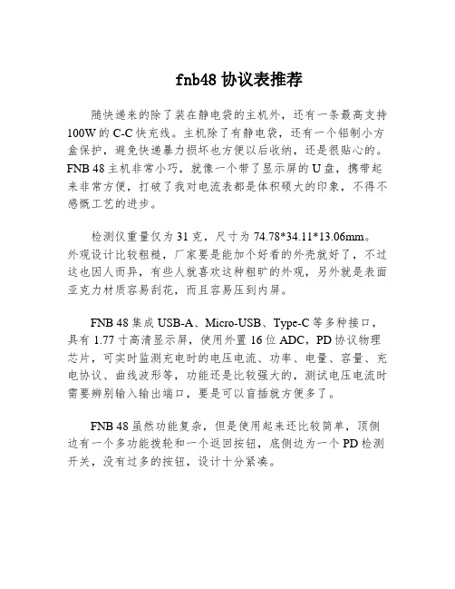
fnb48协议表推荐随快递来的除了装在静电袋的主机外,还有一条最高支持100W的C-C快充线。
主机除了有静电袋,还有一个铝制小方盒保护,避免快递暴力损坏也方便以后收纳,还是很贴心的。
FNB 48主机非常小巧,就像一个带了显示屏的U盘,携带起来非常方便,打破了我对电流表都是体积硕大的印象,不得不感慨工艺的进步。
检测仪重量仅为31克,尺寸为74.78*34.11*13.06mm。
外观设计比较粗糙,厂家要是能加个好看的外壳就好了,不过这也因人而异,有些人就喜欢这种粗旷的外观,另外就是表面亚克力材质容易刮花,而且容易压到内屏。
FNB 48集成USB-A、Micro-USB、Type-C等多种接口,具有1.77寸高清显示屏,使用外置16位ADC,PD协议物理芯片,可实时监测充电时的电压电流、功率、电量、容量、充电协议、曲线波形等,功能还是比较强大的,测试电压电流时需要辨别输入输出端口,要是可以盲插就方便多了。
FNB 48虽然功能复杂,但是使用起来还比较简单,顶侧边有一个多功能拨轮和一个返回按钮,底侧边为一个PD检测开关,没有过多的按钮,设计十分紧凑。
即插即用,无需内置供电。
接入待测设备稍等几秒,主机开机后便可自由选择测试项目。
选择与确认功能都由多功能拨轮实现,左右按动为切换显示,按下则为确认。
长按左键选择PD协议检测时,系统会提示高压警告,此时最好是在空载状态下使用,防止因为高压高电流对设备造成损坏。
检测完成后,支持的协议将在屏幕以绿色字体显示,反之则为红色,返回上一层只需要按下旁边白色的返回键。
设备支持触发单一协议检测也可自动检测全部协议。
FNB 48还支持重力感应,能够自动切换显示方向,方便数据查看,实测感应极为灵敏。
另外还可计算线阻、计算电池容量、PD协议转换等功能,因为平时很少使用,我就不做介绍了。
FNB 48小巧易带,我这一款为无蓝牙版,蓝牙版还可以连接手机实时查看,便捷程度更进一步。
FNB 48紧凑的外观下蕴含着丰富的功能以及简易的操作逻辑,还是不错的,价格也相较于Powe-Z等品牌稍低。
- 1、下载文档前请自行甄别文档内容的完整性,平台不提供额外的编辑、内容补充、找答案等附加服务。
- 2、"仅部分预览"的文档,不可在线预览部分如存在完整性等问题,可反馈申请退款(可完整预览的文档不适用该条件!)。
- 3、如文档侵犯您的权益,请联系客服反馈,我们会尽快为您处理(人工客服工作时间:9:00-18:30)。
Description
• For 1/4" x 1-1/4" and 5mm x 20mm fuses • All holder bodies have the option of using 1/4" x 1-1/4" or 5mm x 20mm carriers
• Withstands 15 to 20 lbs-in torque to mounting nut when mounting fuseholder to panel • High temperature, flame retardant, Thermoplastic meets UL 94 VO
Agency Information
• UL Recognized:IZL T2, E14853• CSA Component Acceptance:Class 6225-01, File 47235
Fuseholders
HTB Panel Mount Series
Replacement Parts
Maximum Panel Thickness
Body Type
Inch Millimeters
HTB-20.307.62HTB-30.307.62HTB-40.125 3.18HTB-50.125 3.18HTB-60.307.62HTB-80.125 3.18HTB-9
0.125
3.18
SPECIFICATIONS
Product Current Voltage Fuse Quick Code Rating Rating Size Connect HTB-X2I 15A 250V 1/4" x 1-1/4"3/16"HTB-X4I 15A 250V 1/4" x 1-1/4"3/16"HTB-X6I 20A 250V 1/4" x 1-1/4"1/4"HTB-X8I 20A 250V 1/4" x 1-1/4"1/4"HTB-X2M 15A 250V 5mm x 20mm 3/16"HTB-X4M 15A 250V 5mm x 20mm 3/16"HTB-X6M 16A 250V 5mm x 20mm 1/4"HTB-X8M 16A
250V
5mm x 20mm 1/4"
Fuseholders
HTB Panel Mount Series
Visit us on the Web at
3601 Quantum Boulevard Boynton Beach, Florida 33426-8638
T el:+1-561-752-5000 T oll Free:+1-888-414-2645 Fax:+1-561-742-1178
This bulletin is intended to present product design solutions and technical information that will help the end user with design applications. Cooper Electronic Technologies reserves the right, without notice, to change design or construction of any products and to discontinue or limit distribution of any products. Cooper Electronic Technologies also reserves the right to change or update, without notice, any technical information contained in this bulletin. Once a product has been selected, it should be tested by the user in all possible applications.
OC-2580 5/02© Cooper Electronic Technologies 2002
PACKAGING CODE
Packaging Code
Description
Blank 10 pieces of fuseholders packed into a carton
BK
100 pieces of fuseholders packed into a cardboard shelf package。