mdls20464_manual
松下实现光盘单面容量27GB

松下实现光盘单面容量27GB
佚名
【期刊名称】《中国科教创新导刊》
【年(卷),期】2000(0)10
【总页数】1页(P20-20)
【关键词】DVD光盘;双层记录;半导体激光;卫星数字电视;激光输出功率;记录膜;记录层;最优化处理;可擦写光盘;薄膜化
【正文语种】中文
【中图分类】TP333.4
【相关文献】
1.白送33%容量松下索尼将推67G蓝光盘 [J], ;
2.提高单面双层BD光盘容量的信号处理技术 [J], 袁海波;
3.27GB储存容量与高兼容性的新一代蓝光光盘——蓝光闪过之后 [J], 刘玉达
4.基于大容量蓝光光盘库的数字档案系统研究与实现 [J], 李茂华;陈易;罗嗣力;孙阳;罗翠华
5.“蓝光”单面容量是目前光盘的35倍 [J],
因版权原因,仅展示原文概要,查看原文内容请购买。
z OS 2.4 ISPF 用户指南 第 1 卷说明书

Chapter 1. Overview of ISPF.................................................................................. 1
Summary of changes for z/OS Version 2 Release 4 (V2R4).................................................................. xxvii Summary of changes for z/OS Version 2 Release 3 (V2R3).................................................................. xxvii Summary of changes for z/OS Version 2 Release 2 (V2R2).................................................................. xxvii
If you have a technical problem............................................................................................................... xxv
Summary of changes........................................................................................ xxvii
PSL646技术说明书V1.40

PSL 646数字式线路光纤电流差动保护装置技术说明书使用说明书编写兰金波楼红勇王家华王胜审核王文雄批准马文龙V1.40二○○二年八月国电南京自动化股份有限公司*本说明书可能会被修改,请注意最新版本资料第一部分技术说明书目次声明 (1)安全标准 (1)1.装置简介 (2)1.1.装置的特点: (3)2.技术参数 (6)2.1额定参数 (6)2.2主要技术性能 (6)2.3绝缘性能 (7)2.4抗电磁干扰性能 (8)2.5机械性能 (8)2.6环境条件 (9)3.装置硬件 (10)3.1.机箱结构 (10)3.2.交流插件 (10)3.3.CPU插件 (11)3.4.电源插件 (13)3.5.逻辑及跳闸插件 (13)3.6.人机对话(MMI)插件 (14)4.保护原理 (15)4.1.光纤电流差动保护原理 (15)4.2.方向元件 (17)4.3.低电压元件 (18)4.4.过电流元件 (18)4.5.零序过电流元件 (18)4.6.反时限元件...................................................................................................................... 错误!未定义书签。
4.7.加速 (18)4.8.三相重合闸(可选) (19)4.9.低频元件(不用).......................................................................................................... 错误!未定义书签。
4.10.过负荷元件(不用) (19)4.11.PT和CT断线检测 (19)4.12.数据记录 (20)5.与变电站自动化系统配合 (21)6.定值及整定说明 (22)6.1.PSL646数字式线路光纤电流差动保护装置的整定值清单及说明 (22)6.2.PSL646数字式线路光纤电流差动保护装置的软压板清单及说明 (25)·声明·声明恭喜您购买了国电南京自动化股份有限公司的数字式保护及自动化产品—数字保护及自动化技术的国内领先者。
机房和施工组织模板

江西新昌电厂“上大压小〞新建工程厂级管理信息系统〔MIS〕网络及硬件平台系统集成投标文件投标编号:03-ct-03-2007-156〔第三卷附件1-技术标准书〕投标人:安徽科大恒星电子商务技术二00九年四月目录第一章概述 (1)工程建设需求 (1)设计原那么 (2)实用性与先进性相结合 (2)可扩展性和开放性 (2)可靠性和平安性 (3)可管理性 (3)设计、施工标准 (3)工程建设目标 (6)第二章效劳器系统平台设计 (7)建设需求 (7)数据库效劳器设计 (7)IBM power550方案 (7)效劳器选型 (7)2.2.1.2 IBM Power 550配置 (12)HP 小型机方案 (13)效劳器选型 (13)2.2.2.2 HP Integrity rx6600 配置 (17)系统运行模式设计 (17)并行处理模式 (18)任务分担模式 (18)主机备用模式 (18)其它效劳器设计 (18)效劳器的部署 (18)物理效劳器与逻辑效劳器之间的关系 (19)效劳器选型设计 (20)2.3.3.1 IBM X3850 M2方案 (20)2.3.3.2 HP ProLiant DL580 G5 效劳器方案 (23)效劳器配置 (26)2.3.4.1 IBM X3850 M2配置 (26)2.3.4.2 HP ProLiant DL580 G5配置 (27)SAN存储系统设计 (27)2.4.1 IBM TotalStorage DS4800方案 (28)2.4.1.1 IBM TotalStorage DS4800介绍 (28)2.4.1.2 TotalStorage DS4800配置 (31)2.4.2 HP StorageWorks EVA8100方案 (32)2.4.2.1 HP StorageWorks EV A8100介绍 (32)2.4.2.2 HP StorageWorks EV A8100配置 (35)光纤交换机选型 (36)2.4.3.1 IBM System Storage SAN2005-B16 特性 (36)2.4.3.2 IBM System Storage SAN2005-B16 配置 (38)数据备份系统 (38)数据备份需求 (38)数据备份方案 (39)2.5.2.1 Veritas的优势 (39)2.5.2.2 Veritas配置 (42)磁带库选型配置 (43)虚拟磁带库选型 (44)第三章网络系统平台设计 (49)网络建设需求 (49)网络拓扑结构设计 (49)分层设计 (49)可靠性保证〔冗余设计〕 (49)网络拓扑实现 (50)核心层设计 (51)接入层设计 (51)远程访问层设计 (51)Cisco解决方案 (51)中心交换机选型 (51)3.3.1.1 Cisco® 6500介绍 (52)3.3.1.2 Supervisor Engine 720 (56)3.3.1.3 Cisco Catalyst 6513配置 (58)接入交换机选型 (59)H3C解决方案 (59)中心交换机选型 (59)H3C S7500E介绍 (60)H3C S7510E配置 (63)接入交换机选型 (63)第四章系统平安设计 (65)系统平安需求 (65)系统平安体系结构 (65)物理设备平安 (65)访问平安 (66)应用平安 (66)数据平安 (66)平安策略 (67)传输通道和传输设备平安 (67)应用平台平安 (68)资源访问平安 (68)网络防病毒 (69)多功能防火墙设计 (70)HillstoneSA-5020介绍 (71)HillstoneSA-5020功能规格 (72)内网核心平安防护系统〔主机加固〕设计 (74)S-NUMEN用途 (74)S-NUMEN功能 (75)S-NUMEN配置 (76)内网主机审计及监管系统 (76)系统功能 (77)系统特点 (79)体系架构 (80)配置 (81)防病毒系统设计 (81)网络防病毒配置 (84)第五章综合布线系统设计 (85)综合布线系统需求 (85)设计标准与设计目标 (85)设计标准 (85)设计目标 (86)布线系统设计 (86)光缆敷设 (86)SAN光纤走向 (86)布线系统测试 (87)测试标准与内容 (89)提交文档 (94)第六章工程组织与管理 (95)工程管理与目标 (95)工程组织及人力资源分配 (96)施工组织总体部署 (96)人力资源配置 (98)与相关单位合作 (99)与工程单位合作 (99)与厂商合作 (100)工程管理 (100)管理方法 (100)管理措施 (101)工程风险管理 (104)工程进度管理 (104)工程质量控制与保证 (105)工程阶段性评估 (106)第七章工程实施方案 (107)工程实施环节规划 (107)实施环节规划总表 (107)设计联络 (109)设备订货及到货 (110)实施现场情况调研 (110)制定详细实施方案 (111)培训 (111)设备验收 (111)查验设备 (111)查验方法 (112)查验报告 (117)系统安装调试 (117)系统调试方案制定 (117)小型机调试 (118)中心交换机调试 (118)边缘交换机调试 (118)中心路由器调试 (119)网管软件调试 (119)主机调试 (119)备份系统调试 (120)系统初验收 (120)试运行 (120)技术文档的提交 (121)系统终验 (121)技术支持与售后效劳 (121)实施进度方案 (121)里程碑事件及考核标准 (122)第八章验收方案与文档 (123)验收测试内容 (123)现场验收测试 (124)文档验收 (126)系统初验收 (126)系统终验 (127)测试方案 (127)测试方法 (127)测试工程 (127)测试方法 (128)工程文档 (129)工程文档内容 (129)工程文档提交方案 (132)第九章机房建设工程 (134)工程简述 (134)电子计算机机房组成及使用面积确定 (134)可维护性设备布置 (135)设计原那么 (135)计算机机房平安分类 (135)建设标准 (137)设计依据 (138)设计依据 (138)设计指标 (140)机柜及机房隔断、装饰设计 (141)机柜 (141)图腾机柜概述 (141)图腾机柜选型 (141)机房隔断 (141)装饰设计 (142)装修材料选材 (142)材料表 (143)吊顶 (143)地面 (144)墙、柱面 (145)门、窗 (145)供配电系统〔含UPS、照明等〕 (146)电气概述 (146)供配电系统 (147)设计标准要求 (147)9.5.2.2 机房配电冗余供电系统 (149)配电设备 (149)UPS系统 (149)UPS选型选型 (149)艾默生“UL33〞系列UPS性能参数 (150)美国“艾默生〞系列UPS特点 (151)电池配置 (151)照明系统设计 (152)普通照明系统设计 (153)应急照明、疏导灯具系统设计 (153)配电线路安装技术 (153)空调系统 (154)空调系统设计 (154)空调设备选型 (154)防雷接地 (154)防雷系统概述 (154)对雷电引入的分析 (155)机房防雷设计 (156)防雷验收及保障 (156)接地系统概述 (156)接地系统解决措施 (157)机房的地线系统 (157)局部等电位连接 (157)抗静电保护地 (157)静电防护 (158)KVM设备及机房布线 (158)KVM设计需求 (158)KVM设计方案说明 (159)环境监控、消防报警及其他相关效劳 (159)环境监控 (159)门禁系统 (159)视频监控 (159)动力环境监控 (159)消防报警 (160)9.9.3 控制台桌椅 (161)灾害处理 (161)机房区防水防护措施 (161)机房给水排水技术 (161)防虫、防鼠害 (162)电磁屏蔽 (162)第一章概述江西新昌电厂网络及硬件平台系统集成工程建设主要包括了网络系统、无线网络覆盖、效劳器系统、存储系统、数据备份系统、微软AD域设计及网络部署、管理及系统软件、MIS终端、智能机房、综合布线等系统,按现代先进技术设计,该系统集成完成后,新昌电厂具有统一的生产MIS系统运行平台,能为其信息化建设提供良好的根底效劳。
Mellanox Switch-IB 2 固件发行说明 Rev 15.2000.2046说明书

Mellanox Technologies Mellanox Switch-IB™ 2 Firmware Release NotesRev 15.2000.20462Mellanox Technologies Mellanox Technologies350 Oakmead Parkway Suite 100Sunnyvale, CA 94085U.S.A.Tel: (408) 970-3400Fax: (408) 970-3403© Copyright 2019. Mellanox Technologies Ltd. All Rights Reserved.Mellanox®, Mellanox logo, Mellanox Open Ethernet®, LinkX®, Mellanox Spectrum®, Mellanox Virtual Modular Switch®, MetroDX®, MetroX®, MLNX-OS®, ONE SWITCH. A WORLD OF OPTIONS®, Open Ethernet logo, Spectrum logo, Switch-IB®, SwitchX®, UFM®, and Virtual Protocol Interconnect® are registered trademarks of Mellanox Technologies, Ltd.For the complete and most updated list of Mellanox trademarks, visit /page/trademarks.All other trademarks are property of their respective owners.NOTE:THIS HARDWARE, SOFTWARE OR TEST SUITE PRODUCT (“PRODUCT(S)”) AND ITS RELATED DOCUMENTATION ARE PROVIDED BY MELLANOX TECHNOLOGIES “AS-IS” WITH ALL FAULTS OF ANY KIND AND SOLELY FOR THE PURPOSE OF AIDING THE CUSTOMER IN TESTING APPLICATIONS THAT USE THE PRODUCTS IN DESIGNATED SOLUTIONS. THE CUSTOMER'S MANUFACTURING TEST ENVIRONMENT HAS NOT MET THE STANDARDS SET BY MELLANOX TECHNOLOGIES TO FULLY QUALIFY THE PRODUCT(S) AND/OR THE SYSTEM USING IT. THEREFORE, MELLANOX TECHNOLOGIES CANNOT AND DOES NOT GUARANTEE OR WARRANT THAT THE PRODUCTS WILL OPERATE WITH THE HIGHEST QUALITY. ANY EXPRESS OR IMPLIED WARRANTIES, INCLUDING, BUT NOT LIMITED TO, THE IMPLIED WARRANTIES OF MERCHANTABILITY, FITNESS FOR A PARTICULAR PURPOSE AND NONINFRINGEMENT ARE DISCLAIMED. IN NO EVENT SHALL MELLANOX BE LIABLE TO CUSTOMER OR ANY THIRD PARTIES FOR ANY DIRECT, INDIRECT, SPECIAL, EXEMPLARY, OR CONSEQUENTIAL DAMAGES OF ANY KIND (INCLUDING, BUT NOT LIMITED TO, PAYMENT FOR PROCUREMENT OF SUBSTITUTE GOODS OR SERVICES; LOSS OF USE, DATA, OR PROFITS; OR BUSINESS INTERRUPTION) HOWEVER CAUSED AND ON ANY THEORY OF LIABILITY, WHETHER IN CONTRACT, STRICT LIABILITY, OR TORT (INCLUDING NEGLIGENCE OR OTHERWISE) ARISING IN ANY WAY FROM THE USE OF THE PRODUCT(S) AND RELATED DOCUMENTATION EVEN IF ADVISED OF THE POSSIBILITY OFSUCH DAMAGE.Rev 15.2000.20463Mellanox Technologies Table of ContentsChapter 1 Overview . . . . . . . . . . . . . . . . . . . . . . . . . . . . . . . . . . . . . . . . . . . . . . 61.1Supported Systems. . . . . . . . . . . . . . . . . . . . . . . . . . . . . . . . . . . . . . . . . . . . . 61.2Firmware Interoperability . . . . . . . . . . . . . . . . . . . . . . . . . . . . . . . . . . . . . . . 61.3Supported Cables and Modules . . . . . . . . . . . . . . . . . . . . . . . . . . . . . . . . . . 61.4Firmware Upgrade . . . . . . . . . . . . . . . . . . . . . . . . . . . . . . . . . . . . . . . . . . . . . 71.5 PRM Revision Compatibility. . . . . . . . . . . . . . . . . . . . . . . . . . . . . . . . . . . . . . 7Chapter 2 Changes and New Features in Rev 15.2000.2046 . . . . . . . . . . . . . . 8Chapter 3 Known Issues . . . . . . . . . . . . . . . . . . . . . . . . . . . . . . . . . . . . . . . . . . . 9Chapter 4 Bug Fixes History . . . . . . . . . . . . . . . . . . . . . . . . . . . . . . . . . . . . . . . 11Chapter 5 Firmware Changes and New Feature History. . . . . . . . . . . . . . . . . 13Rev 15.2000.20464Mellanox Technologies List of TablesTable 1:Release Update History. . . . . . . . . . . . . . . . . . . . . . . . . . . . . . . . . . . . . . . . . . . . . . . .5Table 2:Supported Systems . . . . . . . . . . . . . . . . . . . . . . . . . . . . . . . . . . . . . . . . . . . . . . . . . . .6Table 3:Firmware Interoperability. . . . . . . . . . . . . . . . . . . . . . . . . . . . . . . . . . . . . . . . . . . . . .6Table 4:Changes and New Features. . . . . . . . . . . . . . . . . . . . . . . . . . . . . . . . . . . . . . . . . . . . .8Table 5:Known Issues . . . . . . . . . . . . . . . . . . . . . . . . . . . . . . . . . . . . . . . . . . . . . . . . . . . . . . . .9Table 6:Bug Fixes History . . . . . . . . . . . . . . . . . . . . . . . . . . . . . . . . . . . . . . . . . . . . . . . . . . . .11Table 7:History of Major Changes and New Features . . . . . . . . . . . . . . . . . . . . . . . . . . . . .13Rev 15.2000.20465Mellanox Technologies Release Update HistoryTable 1 - Release Update History Date DescriptionSeptember 8, 2019Initial release of this firmware version.Rev 15.2000.20466Mellanox Technologies 1OverviewThese are the release notes for the Switch-IB™ 2 firmware, Rev 15.2000.2046. This firmware complements the Switch-IB™ 2 silicon architecture with a set of advanced features, allowing easy and remote management of the switch.1.1Supported SystemsThis firmware supports the devices and protocols listed in Table 2. For the most updated list of switches supported, visit the Firmware Download pages on .1.2Firmware InteroperabilityThis FW version has been validated to work against platforms with the following SW versions.1.3Supported Cables and ModulesFor a list of the Mellanox supported cables please visit the LinkX™ Cables and Transceivers page of the Mellanox Website at:/products/interconnect/cables-configurator.phpPlease refer to the LinkX™ Cables and Transceivers webpage (/products/interconnect/cables-configurator.php ) for the full list of supported cables and transceivers.Table 2 - Supported SystemsDevice Part NumberPSID Description MSB7890MT_2640110032Switch-IB™ 2 based EDR InfiniBand switch; 36 QSFP28 ports;externally managedTable 3 - Firmware Interoperability HCA/Switch Firmware VersionSwitch-IB™11.2000.2046SwitchX®-29.4.2000ConnectX®-5 (Ex)16.26.1xxx ConnectX-4 Lx14.26.1xxx ConnectX-412.26.1xxx Connect-IB®10.16.6000ConnectX-3 (Pro)2.42.5000MFT 4.13.0When using Mellanox AOC cables longer than 50m use one VL to achieve full wirespeed.Overview Rev 15.2000.20467Mellanox Technologies 1.4Firmware UpgradeFirmware upgrade may be performed directly from any previous version to this version. To upgrade firmware, please refer to the Mellanox Firmware Tools (MFT) package at:/page/management_tools1.5PRM Revision CompatibilityFirmware Rev 15.2000.2046 complies with the Mellanox Switches Programmer’s Reference Manual (PRM), Rev 1.45 or later.Rev 15.2000.20468Mellanox Technologies 2Changes and New Features in Rev 15.2000.2046Table 4 - Changes and New Features CategoryDescription15.2000.2046PSU’s TemperatureThresholds Now PSU’s temperature thresholds (high and low) can be queried via the MTMP register.Known Issues Rev 15.2000.20469Mellanox Technologies 3Known IssuesTable 5 describes known issues in this firmware release and possible workarounds.Table 5 - Known Issues Internal Ref.Issue955641Description : VL_HIGH_LIMIT is not affecting the VL arbiter as expected.Workaround : Arbitration table should be set using only the low priority VL arbitrationtableKeywords : VL Arbitration1249608Description : Configuring weight “0” for VL, results in unexpected behavior.Workaround : Arbitration table should be configured with weights other than “0”.Keywords : VL Arbitration982005Description : When connecting 6 & 7 meters, link may raise DDR instead of QDR againstGD4000/IS5000 switches.Workaround : N/AKeywords : Link-Description : Congestion control 1.3 supports congestion log only.Workaround : N/AKeywords : QoS-Description : VL2VL mode is not supported from an aggregation port to an egress port.Workaround : N/AKeywords : SHARP-Description : FDR link may rise with symbol errors on optic EDR cable longer than 30M.Workaround : N/AKeywords : Link-Description : Port LEDs do not flash on system boot.Workaround : N/AKeywords : LEDs-Description : Link width reduction is not supported in this release.Workaround : N/AKeywords : Power Management-Description : If QDR is not enabled for the switch's InfiniBand Port Speed while connectedto ConnectX-3/Pro or Connect-IB® FDR adapters or to SwitchX® /SwitchX®-2 FDRswitches, links will rise at SDR or DDR (even if FDR is enabled).Workaround : Enable QDR (in addition to FDR) when connecting to peer ports running atFDRKeywords : InteroperabilityRev 15.2000.204610Mellanox Technologies -Description : Force FDR10 is not supported on EDR products.Workaround : To raise link with an FDR10 device, make sure all speeds, including EDR,are configured on Switch-IB.Keywords : Interoperability-Description : Fallback Routing is not supported for DF+ topology. Fallback Routing Notifi-cations and Adaptive Routing notifications are not supported for topologies others thentrees.Workaround : N/AKeywords : Network-Description : Module info page in Diagnostics Data VS-MAD is not supportedWorkaround : N/AKeywords : Diagnostics Data VS-MADTable 5 - Known IssuesInternal Ref.IssueBug Fixes History4Bug Fixes HistoryTable 6 - Bug Fixes HistoryInternal Ref.Issue1786686Description: Wrong behavior of ARGroupTableCopy MAD.Keywords: Adaptive RoutingDiscovered in Release: 15.2000.1142Fixed in Release: 15.2000.16001730194Description: In rare cases, when connecting between Switch-IB/Switch-IB 2 and Quantumswitch systems, traffic lose might occur.Keywords: Traffic, Switch-IB/Switch-IB 2, QuantumDiscovered in Release: 15.2000.1000Fixed in Release: 15.2000.11421337469Description: In rare cases, when a receiver’s electrical eye is narrow, link might raise withBER higher (worse) than 10-12.Keywords: LinkDiscovered in Release: 15.1500.0034Fixed in Release: 15.1630.02061092005Description: Enable SDR speed regardless of cable supported speedsKeywords: LinkDiscovered in Release: 15.1400.0102Fixed in Release: 15.1500.01061089528Description: SHARP not functional in case of groups larger than 14 membersKeywords: SHARPDiscovered in Release: 15.1430.0160Fixed in Release: 15.1500.0106964972Description: In info block 29 (Thermal algorithm values):DELTA TEMP REPORTING > '4' will be considered '1'.DELTA TEMP REPORTING = 1,2,3 returns no issues.Keywords: Thermal ManagementDiscovered in Release: 15.1310.0138Fixed in Release: 15.1310.0150-Description: VL arbitration does not distribute traffic as expected in case of multiple VLsKeywords: GeneralDiscovered in Release: 15.1200.0102Fixed in Release: 15.1300.0100Table 6 - Bug Fixes HistoryInternal Ref.Issue-Description: In rare cases, FDR links may rise with errors. (Improved BER performance.) Keywords: LinkDiscovered in Release: 15.1.1002Fixed in Release: 15.1300.0092Firmware Changes and New Feature History5Firmware Changes and New Feature HistoryTable 7 - History of Major Changes and New FeaturesCategory Description15.2000.1600Bug Fixes See Section 4, “Bug Fixes History,” on page 1115.2000.1142Bug Fixes See Section 4, “Bug Fixes History,” on page 1115.2000.1000Chassis Management Changed the PSU voltage read from “V out” to “Vin”.General System stability improvements.15.1910.0618General Added support for PortStateTable standard SMP MADChassis Management Added support for PSU utilization and consumption of output powerChassis Management Added support for PSU temperature and 12V V out monitoring15.1701.0010General Added support for congestion control log 1.3 as described in IBTA IB specifica-tion release 1.3, Annex A10General Added additional information (PDDR pages as described in the Switches PRM,section 8.15.50 PDDR - Port Diagnostics Database Register) to diagnostics dataVS-MAD as described in Mellanox Vendor Specific MAD Specification 1.3 sec-tion 3.33 – DiagnosticDataChassis Management Added ability to read part numbers and serial numbers for fans (by using MFNRregister) and the power supply (by using MSPS register)15.1610.0210SHARP Added support for SHARP reproducibility configuration15.1610.0206General Bug fixes15.1610.0200Chassis Management Added ability to read part numbers and serial numbers for fans (by using MFNRregister) and the power supply (by using MSPS register)15.1610.0196General Added support for congestion control log 1.3 as described in IBTA IB specifica-tion release 1.3, Annex A10General Added additional information (PDDR pages as described in the Switches PRM,section 8.15.50 PDDR - Port Diagnostics Database Register) to diagnostics dataVS-MAD as described in Mellanox Vendor Specific MAD Specification 1.4 sec-tion 3.33 – DiagnosticDataTable 7 - History of Major Changes and New FeaturesCategory DescriptionSHARP Added support for group join optimization using root GID as described in Mella-nox Vendor Specific MAD Specification 1.4 section 4.10 – Aggregation GroupJoin15.1500.0106General Added support for IB telemetry, Top Talkers.For more details, refer to section “Congestion Telemetry” in the MellanoxSwitches Programmer’s Reference Manual.Module Added support for 100GbE PSM4/LR4 modules.15.1430.0160General Added support for Adaptive Routine (AR) optimizations with ConnectX-5 (RCMode)Link Added support for Force EDR on Switch IB systems as described in MellanoxSwitches Programmer's Reference Manual (PRM) under PTYS Register15.1400.0102General Added support for IB telemetry, Congestion Monitoring-Thresholds (See Mella-nox Switches PRM (Programmer's Reference Manual) - section 9.7 - CongestionTelemetry).General Added support for Additional Port Counters Extended (See IB Specification V ol1-Release-1.3, MgtWG 1.3 Errata).General Added support for IB Router Port (Port 37) Counters (See IB Specification V ol 1-Release-1.3).15.1300.0126General Added support for burst/traffic histograms (described in Vendor Specific MADPRM Rev 1.3, Section 3.33 – Mellanox Performance Histograms)Link Added support for Port PHY Link Mode (PLLM) register (For register descrip-tion, See Switch PRM - PPLM - Port Phy Link Mode)Link Added support for QSFP copper cables which do not publish attenuation in thememory map15.1200.0102General Added support for SHARP performance improvements (UD, Group trimming) General Added support for fast flash burn with new register MFMC and updates to currentflash burn register MFPA (according to Section 3.9 of the Switches PRM)Link Added support for PRBS generation tool (according to registers PPTT and PPRTregisters in Section 7.14 of the Switches PRM)Link Added support for new PHY statistical counters group to register PPCNT (accord-ing to Section 7.14 of the Switches PRM)15.1100.0072General Added support for SHARPSystem Management Added system MKey supportFirmware Changes and New Feature HistoryTable 7 - History of Major Changes and New FeaturesCategory DescriptionChassis Management Added support of IB NodeDescription SetModules Added support for reading from pages with password through cable info MADFor more information, please refer to register MCIA in the Switch PRM and theCableinfo VS-MAD15.0400.0064General First beta-level releaseGeneral Added support for port mirroringGeneral Added support for SHARPGeneral Improved support for adaptive routing, adaptive routing notification, fault rout-ing, fault routing notificationLink Removed out-of-the-box Forward Error Correction (FEC), reaching 90ns latency,on Mellanox GA level AOCs equal to or shorter than 30m.•MFA1A00-EXXX: 3, 5, 10, 15, 20, 30Link Added support for FDR10 speedChassis Management Added support for power supply monitoring (for more information please refer tothe MSPS register in the SwitchX Family Programmer’s Reference Manual)。
爱德华斯传统触发器目录说明书
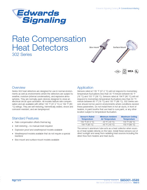
Page 1 of 4 D A T A S H E E TS85001-0589Not to be used for installation purposes. Issue 2Edwards Signaling Catalog uConventional InitiatingMEARate Compensation Heat Detectors302 SeriesBox mount Surface MountOverviewSeries 302 heat detectors are designed for use in normal environ-ments as well as environments where the detectors are subject to weather, moisture (internal condensation), and explosive atmo-spheres. They are normally-open devices designed to close an electrical circuit upon activation. All models feature rate compen-sation and are available with either 135 °F (57.2 °C) or 194 °F (90 °C) ratings. They are self restoring, hermetically sealed, shock and corrosion resistant, and are tamperproof.Standard Features• Rate compensation offsets thermal lag • Self-restoring – no manual reset required• Explosion proof and weatherproof models available • Weatherproof models available that do not require a special backbox • Box mount and surface mount models availableApplicationSensors rated at 135 °F (57.2 °C) will not respond to momentary temperature fluctuations less than 30 °F/minute between 60 °F (16 °C) and 100 °F (38 °C). Sensors rated at 194°F (90 °C) will not respond to momentary temperature fluctuations less than 50 °F/minute between 60 °F (16 °C) and 150 °F (66 °C). 302 Series sen-sors should not be used in environments where conditions exceed these parameters. Do not install them in hot air ducts, in front of heaters, in paint booths that use heat to cure paint, or any otherlocation subject to temperature fluctuation.194 °F (90 °C)-40 °F (-40 °C)150 °F (66 °C)The sensor's aluminum tube acts as a heat collector when sourc-es of heat radiate directly on the tube. Install these sensors out of direct sunlight and away from radiating heat sources including the direct flow from heaters and heat ducts.Page 2 of 4 D A T A S H E E TS85001-0589Not to be used for installation purposes. Issue 2Typical WiringElectrical Rating6-25 VDC 1 amp 125 VDC0.5 ampMaintenance302 Series heat sensors are low maintenance. Sensors automati-cally restore when temperatures drop below their rated tempera-tures. The accumulation of dust and dirt does not normally affect the sensors’ operation.TestingTesting for operation is simple and can be done before or after the sensor has been installed. Heat the sensor with a hair dryer (do not use any device with an open flame to test sensors). The sen-sor should operate shortly after the hot air is applied.Refer to NFPA 72, National Fire Alarm Code and/or the localauthority having jurisdiction to determine testing frequency, record keeping, and other testing considerations.Rate Compensation302 Series sensors feature rate compensation, which improves performance by offsetting thermal lag, an inherent property of conventional fixed temperature heat sensors.A slow rate of temperature rise allows the heat to penetrate the inner expansion struts. The tubular shell and the struts expand slowly until the total device has been heated to its rated tempera-ture level of 135 °F (57.2 °C) or 194 °F (90 °C). At this point, the silver contact points close and an alarm is initiated.When subjected to a rapid rate temperature rise, there is not as much time for heat to penetrate the inner strut. However, the rapid lengthening of the shell allows the struts to come together at a lower level.When the surrounding air temperature returns to below the rated level, the shell contracts, forcing the contacts to open, thus auto-matically resetting the sensor.Fine silver contact Expansion strutsHigh expansion sensingshell, 0.040 anodized aluminum Heat control sleeve Setting screwDevcon hermetic sealWARNING – Use For Property Protection Only: Heat detectors do not protect life against fire and smoke. In most fires, hazardous levels of smoke, heat and toxic gases can build up before a heat sensor would initiate an alarm. Independent studies indicate that heat sensors should only be used when property protection alone is involved. In cases where life safety is a factor, the use of smoke detectors is recommended.Under no circumstances should heat detectors be relied upon as the sole measure to ensure fire safety. However, if they are spaced in accordance with the specifications found under Application, these sensors can contribute, within an overall fire safety program, to reducing the risk of avoid-able property losses.When used with automatic fire suppression systems such as pre-action and deluge sprinkler systems, carbon dioxide systems, halon systems, and dry chemical systems, at least two sen-sors should be used to initiate the alarm. This is commonly referred to as cross-zoning or prioritymatrix zoning and is necessary to eliminate premature discharge of the system. Refer to NFPA 72 for more information.Detector Spacing(all models)(15.2 x 15.2 m)(15.2 x 15.2 m)(15.2 x 15.2 m)(12.2 x 12.2 m)UL- Horizontal Spacing (all models)40' x 40' (12.2 x 12.2 m)40' x 40' (12.2 x 12.2 m)40' x 40' (12.2 x 12.2 m)30' x 30' (9.1 x 9.1m)FM - Horizontal or vertical spacing.*30' x 30' (9.1 x 9.1m)30' x 30' (9.1 x 9.1m)30' x 30' (9.1 x 9.1m)Not ListedSpacing is based on smooth ceilings that are up to 10' (3 m) high. Refer to NFPA 72 for ceilings that are not considered smooth or are higher than 10' (3 m).* EPM models are not FM approved.DimensionsTube Diameter 0.5" (12.7 mm)0.5" (12.7 mm)NPT Thread 0.5" (12.7 mm)0.5" (12.7 mm)Hex Base1" (25.4 mm) plastic1.25" (31.75 mm)brassOrdering InformationJALX11Explosion proof outlet body with cover (½" thread hubs back, four sides and cover) - Killark 3.5 lb. (1.6 kg)Page 3 of 4D A T A S H E E T S85001-0589Not to be used for installation purposes. Issue 2Contact us...Phone: 1-800-336-4206Web: Edwards Signaling isan EDWARDS brand.3 Farm Glen BoulevardFarmington, CT 06032In Canada, contact Chubb Edwards...Email: **************************Web: © 2013 UTC Fire & Security AmericasCorporation, Inc. All rights reserved.Specifications subject to changewithout notice. Edwards is part of UTCClimate, Controls & Security, a unit ofUnited Technologies Corporation.06-27-13 Page 4 of 4D A T A S H E E T S85001-0589Not to be used for installation purposes. Issue 2。
psl640 系列数字式线路保护装置技术使用说明书

4.10 低压解列元件 ..........................................................................................................................18 4.11 过负荷元件...............................................................................................................................19 4.12 PT 断线检测 ............................................................................................................................19 4.13 小电流接地选线.......................................................................................................................19 4.14 数据记录...................................................................................................................................19 5 与变电站自动化系统配合 .......................................................................................................... 20 6 定值及整定说明 .......................................................................................................................... 21 6.1 PSL 641 PSL 643 数字式线路保护装置的整定值清单及说明 ..........................................21 6.2 PSL 641 PSL 643 数字式线路保护装置的软压板清单及说明 ..........................................24
xpt2046中文资料_数据手册_参数
XPT2046 Data Sheet
2007.5
Copyright©2007, SHENZHEN XPTEK TECHNOLOGY CO.,LTD
1/30
XPT2046 Touch Screen Controller
Copyright©2007, SHENZHEN XPTEK TECHNOLOGY CO.,LTD
2/30
XPT2046 Touch Screen Controller
General Description
The XPT2046 is a 4-wire resistive touch screen controller that incorporates a 12-bit 125 kHz sampling SAR type A/D converter. The XPT2046 operates down to 2.2V supply voltage and supports digital I/O interface voltage from 1.5V to VCC in order to connect low voltage uP. The XPT2046 can detect the pressed screen location by performing two A/D conversions. In addition to location, the XPT2046 also measures touch screen pressure.On-chip VREF can be utilized for analog auxiliary input, temperature measurement and battery monitoring withthe ability to measure voltage from 0V to 5V. The XPT2046 also has an on-chip temperature sensor The XPT2046 is available in 16pin QFN thin package(0.75mm in height) and has the operating temperature range of -40°C to +85°C
- 1、下载文档前请自行甄别文档内容的完整性,平台不提供额外的编辑、内容补充、找答案等附加服务。
- 2、"仅部分预览"的文档,不可在线预览部分如存在完整性等问题,可反馈申请退款(可完整预览的文档不适用该条件!)。
- 3、如文档侵犯您的权益,请联系客服反馈,我们会尽快为您处理(人工客服工作时间:9:00-18:30)。
第三章 字符型液晶显示模块特性
一 产品型号定义
1 VP系列产品型号定义
VPC—16465—SC—HT—LED04
VPC 16465 SC
HT
LED04
产品序列号 VPG — 点阵图形 VPC — 点阵字符
点阵数
驱动电源方式 空 外供驱动电源 SC 内置驱动电源
带温补电路
工作温度范围 空 0 +60
HT -20 +70
40466 点阵数
HT
工作温度
HV
驱动电压类型
G
STN模式: G — 黄/绿模式 S — 银色模式 B — 蓝模式 反显
F — 黑/白模式 带有补偿膜的FSTN型 D — 黑/白模式 双STN型
LED04 背光类型 LED01 LED02 LED03 LED04 EL CCFL
Y
背光颜色 Y — 黄 G — 绿 R — 红
单位 ns ns ns ns ns ns ns
点阵字符型液晶显示模块使用手册
(3) 信号真值表
RS
R/W
0
0
0
1
1
0
1
1
E
下降沿 高电平 下降沿 高电平
功能
写指令代码 读忙标志和AC值 写数据 读数据
五 MDLS系列电特性
(1)绝对最大值范围
项目
电路逻辑电压(V) 液晶驱动电压(V) 输入电压(V)
第四章
字符型液晶显示模块指令集……………………… 8
第五章
字符型液晶显示模块应用…………………………… 10
附录一
HD44780的内部字符集……………………………… 20
附录二
MDLS系列产品供电电路…………………………… 21
附录三 附录四
精电蓬远公司维修服务规范………………………… 22 点阵字符型液晶显示模块目录及其尺寸图………… 23
七 模块的存储 若长期 如几年以上 存储 我们推荐以下方式 1. 装入聚乙稀口袋 最好有防静电涂层 并将口封住 2. 在-10°C∼ +35°C 之间存储 3. 放暗处 避强光 4. 决不能在表面压放任何物品 5. 严格避免在极限温/湿度条件下存放
-3-
点阵字符型液晶显示模块使用手册
八 责任范围及维修 在您购买液晶显示模块时 精电蓬远将会为您做显示模块的检测 确保您所买的显
字符型液晶显示模块目前在国际上已经规范化 无论显示屏规格如何变化 其电特 性和接口形式都是统一的 因此只要设计出一种型号的接口电路 在指令设置上稍加改 动即可使用各种规格的字符型液晶显示模块
第一章 注意事项
十分感谢您购买我公司的产品 在使用前请您首先仔细阅读以下注意事 项 以免给您造成不必要的损失 您在使用过程中遇到困难时 请打拨打我们 的技术服务电话 我们将尽力为您提供服务和帮助
第二章 字符型液晶显示模块的基本特点
1. 液晶显示屏是以若干个5 8或5 11点阵块组成的显示字符群 每个点阵块为一个字 符位 字符间距和行距都为一个点的宽度
2. 主 控 制 驱 动 电 路 为 HD44780 HITACHI 及 其 他 公 司 全 兼 容 电 路 如 NT3881 NOVATEK KS0066 SAMSUNG SPLC78A01 SUNPLUS
一 处理保护膜 在装好的模块成品表面贴有一层保护膜 以防在装配时沾污显示表 面 在整机装配结束前不得揭去 以免弄脏或损坏显示面
二 加装衬垫 在模块与前面板之间最好加装一块约0.1毫米左右的衬垫 面板还应保持平整 以免在装 配后产生扭曲 并可提高其抗振性能
三 严防静电 模块中的控制 驱动电路是低压 微功耗的CMOS电路 极易被静电 击穿 静电击穿是一种不可修复的损坏 而人体有时会产生高达几 十伏或上百伏的高压静电 所以 在操作 装配以及使用中都应极 其小心 严防静电 为此 1. 不要用手随意去摸外引线 电路板上的电路及金属框 2. 如必须直接接触时 应使人体与模块保持在同一电位 或将人 体良好接地 3. 焊接使用的烙铁和操作用的电动工具必须良好接地 没有漏 电 4. 不得使用真空吸尘器进行清洁处理 因为它会产生很强的静 电 5. 空气干燥 也会产生静电 因此 工作间湿度应在RH60%以上 6. 取出或放回包装袋或移动位置时 也需小心 防止产生静电 不要随意更换包装或 舍弃原包装
8+* 8+.
9TKV G1RGT CVKQP
项目
使能周期 使能脉冲宽度 使能升 降时间 地址建立时间 地址保持时间 数据建立时间 数据保持时间
符号
TcycE Pweh Ter,Tef Tas Tah Tdsw
Th
最小值
1000 450
140 10 195 10
最大值
25
(2) 读操作 HD44780至MPU
4GCF1RGTCVKQP
项目 使能周期 使能脉冲宽度 使能升 降时间 地址建立时间 地址保持时间 数据延迟时间 数据保持时间
符号 TcycE Pweh Ter,Tef
Tas Tah Tddr Tdhr
-6-
最小值 1000 450
140 10
10
最大值 25 320
单位
ns ns ns ns ns ns ns
2. HD44780读 写操作 (1) 写操作 MPU至HD44780
8+*
45
8+.
V#5
8+* 8+. V#*
49 '
8+.
29'*
8+* 8+.
V'T
8+* 8+. V &59
8 +. V#* V'H
V*
8+.
&$VQ&$
8+* 8+.
8CNKFFCVC V E[E'
N
显示模式 空缺 — 正向显示 N — 负向显示
12
视角方向 空缺 — 6点钟向 12 — 12点钟方向
3 QH系列产品型号定义
QH前缀代表精电蓬远定制的标准屏 其余部分同MDLS系列产品型号定义
二 点阵字符型液晶显示模块产品规格 见附录四
三 点阵字符型液晶显示模块电路框图
四 字符型接口特性及时序
1. 引脚功能
3. 具有字符发生器ROM可显示192种字符 160个5 7点阵字符和32个5 10点阵字符 见附录一
4. 具有64个字节的自定义字符RAM 可自定义8个5 8点阵字符或4个5 11点阵字符 5. 具有80个字节的RAM 6. 标准的接口特性 适配M6800系列MPU的操作时序 7. 模块结构紧凑 轻巧 装配容易 8. 单+5V电源供电 宽温型需要一个 7V的驱动电源 9. 低功耗 长寿命 高可靠性
引脚号
符号
状态
功能
1
Vss
电源地
2
Vdd
+5V逻辑电源
3
V0
液晶驱动电源
4
RS
输入 寄存器选择 1 数据 0 指令
5
R/W
输入 读 写操作选择 1 读 0 写
6
E
输入 使能信号 MDLS40466未用 符号NC
7
DB0
三态 数据总线 LSB
8
DB1
三态 数据总线
9
DB2
三态 数据总线
10
DB3
三态 数据总线
-1-
点阵字符型液晶显示模块使用手册
前言
MDLS 是精电蓬远公司一个字符型液晶显示模块系列 LCM 标号的代码词 头 该系列是目前世界上品种最全的字符型LCM系列 它具有8 1 40 4 字符 行 各种规格 广泛应用于智能仪表 通讯 办公自动化及军工等领域
字符型液晶显示模块由字符型液晶显示屏 LCD 控制驱动主电路HD44780及其扩 展驱动电路HD44100或与其兼容的IC 少量阻 容元件 结构件等装配在PCB板上而成
五 焊接 在焊接模块外引线 接口电路时 应按如下规程进行操作 1. 烙铁头温度小于280°C 2. 焊接时间小于3∼4s 3. 焊接材料 共晶型 低熔点 4. 不要使用酸性助焊剂 5. 重复焊接不要超过3次 且每次重复需间隔5分钟
六 模块的使用与保养 1. 模块的外引线决不允许接错 在您想调试液晶模块时 请注意正确接线 尤其是正 负电源的接线不能有错 否则可能造成过流 过压 烧毁电路上的芯片等对液晶模块 元器件有损的现象 2. 模块在使用时 接入电源及断开电源 必须在正电源稳定接入以后 才能输入信号电 平 如在电源稳定前或断开后输入信号电平 有可能损坏模块中的IC及电路 3. 模块使用时 接入逻辑电源和驱动电源的顺序应是先逻辑电源 后驱动电源 断电 时 应先驱动电源 后逻辑电源 这样做有助于保持屏的良好显示效果和避免在上 电 断电时的电压冲击损坏 所以推荐使用带控制的DC-DC电源做为模块的驱动电源 4. 点阵液晶模块显示时的对比度 视角与温度 驱动电压关系很大 所以 如果VEE调整 过高 不仅会影响显示 还会缩短模块的使用寿命 5. 因为液晶材料的物理特性 液晶的对比度会随着温度的变化而相应变化 所以 您加 的负电压值应该随温度作相应的调整 大致是温度变化10 电压变化1伏 为满足这 一要求 您可做一个温度补偿电路 或者安排一个电位器 随温度调整负电压值 6. 不应在规定工作温度范围以外使用 并且不应在超过存储极限温度的范围外存储 如 果温度低于结晶温度 液晶就会结晶 如果温度过高 液晶将变成各向同性的液体 破坏分子取向 使器件报废 7. 用力按压显示部分 会产生异常显示 这时切断电源 稍待片刻 重新上电 即恢复 正常 8. 液晶显示器件或模块表面结雾时 不要通电工作 因为这将引起电极化学反应 产生 断线 9. 长期用于阳光及强光下时 被遮部分会产生残留影像