ILD615-4中文资料
REF615产品指南
REF615产品指南产品介绍:主要特点:1.多功能:REF615可提供多种保护功能,包括过流、短路、接地故障等,保证电网的安全和可靠运行。
2.可编程性:用户可以根据具体应用需求,通过软件灵活地配置和编程REF615的参数和功能。
3.高性能:REF615采用先进的数字技术和算法,具有高速、高精度的测量和计算能力。
5.易于安装和维护:REF615采用模块化设计,安装和维护非常方便,能够快速恢复电网的正常运行。
6.高可靠性:设备采用高品质的元器件和先进的保护算法,能够实时监测和响应系统故障,确保设备的可靠性和稳定性。
主要应用:1.配电网自动化:REF615可以实现对配电网的保护和控制,包括开关自动化、故障检测和定位、负荷管理等功能。
2.工业应用:REF615适用于各种工业电气设备和系统的保护和控制,如发电机、变压器、电动机等。
3.特殊应用:REF615还可以应用于特殊场景,如风力发电、光伏发电等新能源系统的保护和控制。
安全性能:1.压裂疲劳:REF615具有先进的压裂疲劳保护功能,能够实时监测设备的运行状态,防止过载造成的损坏。
2.跨相保护:设备内置的跨相保护功能能够在相间短路发生时迅速切断电路,避免事故扩大。
3.欠电压保护:REF615能够监测电网的欠电压情况,及时采取措施保护设备和系统的安全运行。
技术参数:1.额定电压:根据具体应用需求可选定。
2.额定电流:根据具体应用需求可选定。
3.工作温度范围:-25℃至+70℃。
4.输入/输出通道:根据具体应用需求可选定。
安装步骤:1.将REF615设备安装在合适的位置,并根据接线图连接设备和电路。
2.连接电源和通讯线路,确保设备工作正常。
3.使用相应的软件对设备进行编程和配置,设置保护参数和功能。
4.完成设备的调试和测试,确保其正常工作。
5.进行设备的检查和维护,定期对设备进行保养和升级。
总结:REF615是一款功能强大、灵活可编程的数字继电保护和控制设备,具有广泛的应用范围和高性能特点。
ABB 615系列保护设备固件更新 4.0.7 说明说明书

ABB OyDistribution Solutions P.O. Box 699FI-65101 Vaasa FINLAND Visiting Address Strömberg Park,Muottitie 2 A FI-65320 Vaasa FINLAND Phone: +358 10 2211Fax: +358 1022 41599e-mail:first st name @Business identity code:0763403-0Domicile: Helsinki www.abb.fiFirmware update release 4.0.7 for 615 series IEC product version 4.0protection relaysScopeFirmware update release 4.0.7 is for the following 615 series protection relays:▪REF615▪REM615▪RET615▪REU615▪RED615To verify that the firmware update applies to the protection relay version, ensure that the second and last two characters of the order code on the label on top of the human-machine interface (HMI) match the corresponding characters of the order code in Fig. 1.Fig 1.Order code of the 615 series protection relaysTo identify the current firmware revision of the 615 series protection relay, please refer to Fig. 2.Fig. 2 Current firmware revision of the 615 series protection relayDocument class Release Note Document ID 2NGA001102Business Unit ABB Oy, Distribution Solutions Page 1/6Date21.09.202121.09.2021Date2/6PageFirmware update releaseSubjectImplemented usability improvementThe firmware update release includes usability and operational improvement. The following improvements has been implemented:1Firmware update release 4.0.7:Cyber Security▪Cyber Security improvements to the "Ripple20" vulnerability in TCP/IP communication stack for normal product usage conditions. Following vulnerabilities (CVE, Common Vulnerabilities andExposures) has been identified in the product and fixed by the update:• CVE-2020-11907• CVE-2020-11909• CVE-2020-11910• CVE-2020-11911• CVE-2020-11912Note! Some of the security scanners might still report existence of Ripple20 vulnerability after the update. This is a false positive, since the scanners indicate the presence of the IP stack, without being able to check the vulnerability and its fixes.Supervision▪Improvement to relay CPU FPGA (IRF 83) internal fault supervision – the supervision interval speed is fastened to reach faster issue detection.▪Improving Time counter rollover in relay’s communication module that may have caused internal relay fault with error code IRF116 COM card error and relay to self-reboot after time interval(s)which is divisible by ~50 days from previous restart.▪Self-supervision improvement for composition detection.▪Internal diagnostic improvement for the self-supervision.1The relay firmware update may also include some minor usability improvements not listed in this note.21.09.2021Date3/6PageFirmware update releaseSubjectProtection▪Improvement to Intermittent earth-fault protection function (INTRPTEF) in “Intermittent EF” mode in case of very small earth fault current Io and high earth fault voltage Uo.Communication▪Improvement to the Frequency measurement FMMXU avoids unnecessary reporting during momentary vector shift situations.▪Improvement on GOOSE receiving. In a system where one relay is receiving GOOSE communication from multiple senders, it is possible that a communication break in one sendermight impact handling of received values from other senders.▪Improvement on line differential protection communication for LD frame sending to remove occasionally happened excess delay in it.Firmware update release 4.0.6:Control▪Improvement to the synchrocheck function for preventing unexpected short-period reset of SYNC_OK output. The reset could have be seen in vector shift situations earlier.▪Improvement to the synchrocheck function for preventing unexpected short-period reset of SYNC_OK output. The reset could have be seen in very rare situations earlier even when thesynchronism conditions were fulfilled and voltages were aligned on both sides of the breaker. Firmware update release 4.0.5:Control▪Manual control of function block OLATCC1 is now enabled for “Operator” user of the relay.HMI▪Enhanced programmable LED response for ensuring update of the programmable LEDs on the LHMI during open/close command.▪The Local HMI object control selection behavior improved while user log in and log out.21.09.2021Date4/6PageFirmware update releaseSubjectMeasurement▪The updating of the minimum demand value calculation is improved for function block PEMMXU when the measurement is under minimum power limit.▪Unnecessary warning is not any more generated by the self-supervision of the RTD measurements in REM615 motor protection relay.Communication▪The relay is able to start up normally even if vertical communication data sets are empty or not available at all.▪ARP table size increased to hold more client IPs.IEC 61850:▪Improved GOOSE sending performance at high application load, e.g. when using complex configurations.▪The performance enhancement for system communication (MMS) event sending during extremely high event load situations.IEC 103:▪Improvement in Rated primary value (RPV) and rated secondary value (RSV) of the IEC 103 for preventing that the U0 value is constantly zero in IEC 103 disturbance recording.▪Improvement in the time stamp of the disturbance recording for preventing that minutes in the IEC 103 disturbance record might occasionally be incorrect▪The transmission handling of the disturbance recorder has been improved for IEC 103 protocol when uploading with very fast reading cycles.▪CRC check sum calculation improved for retransmitted variable-length messages with certain masters in IEC 103 protocol.Modbus:▪Improved refreshing logic of current measurement value for Modbus protocol.DNP 3.0:▪The DNP3.0 Rx buffering has been improved to prevent a situation where the DNP3.0 response sequence numbers are occasionally lagging behind the requested sequence numbers.21.09.2021Date5/6PageFirmware update releaseSubjectSupervision▪Audit trail handling is improved during restart situation.▪Self-supervision coverage of the RAM memory has been improved.▪Improved failure tolerance of the file system for preventing a possible file opening failure, resulting “CRC error” indication on the Local HMI, after restarting of the relay.▪Self-supervision improved to prevent the unnecessary error message “57 Light sensor error” when ARCSARC functionality is not supported.▪The internal diagnostic logging of the line differential communication in RED615 relay has been enhanced.21.09.2021Date6/6PageFirmware update releaseSubjectUpdate procedureFirmware updates represent an integral part of ABB’s life cycle management of distribution protection and control relays. The updates ensure optimized usability throughout the relay’s entire life cycle by offering the latest improvements. The ideal time for a firmware update would be at device commissioning, during periodical testing or a maintenance break.All 615 series IEC version 4.0 (XE) product deliveries manufactured later than August 20th, 2021 include the stated relay firmware update 4.0.7 or newer.Please note that ABB will not be liable for any direct or indirect costs related to the firmware update procedure. The update procedure shall be performed at the sole responsibility of the possessor of the devices.。
REF615通讯协议手册
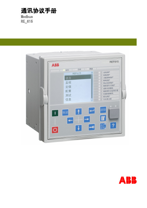
Modbus 标准.................................................7 串行通讯.................................................7 以太网通讯...............................................7 数据应用设备 ............................................8
© 版权 2008 ABB. 版权所有
版权
未经 ABB 书面允许,不得复制本文件的任何部分,不得将其内容透露给第三 方或进行任何未经授权的应用。
本文件中所述的软件和硬件受许可证保护,任何使用、复制或公开应符合许可 证的条款。
商标 ABB 是 ABB 集团的注册商标。本文件中提及的所有其他品牌或产品名称可能 是其持有者的注册商标。
1
目录
章节 4 章节 5
时间的更新...........................................19 控制操作................................................20
控制功能.............................................21 通过 4X 寄存器结构进行的控制操作.....................21 其它的控制操作.......................................23 系统状态寄存器 .........................................24 SSR1.................................................24 SSR2 ................................................25 SSR3 ................................................25 SSR4 ................................................26 SSR5 ................................................27 SSR6 ................................................27 用户定义数据.........................................28 事件记录 ...............................................30 事件记录结构.........................................30 事件读取.............................................31 其他事件记录寄存器...................................32 多事件读取...........................................35 故障录波 ...............................................37 故障录波读取.........................................37 其他故障录波寄存器...................................39 定值组选择..............................................40 时间同步 ...............................................40 实时时钟结构.........................................40 写入实时结构.........................................40 继电保护装置信息........................................41 ASCII 字符编码.......................................42 ASCII 字符串语法.....................................42 复位时间结构............................................42
基于IAP15W4K58S4单片机的信号发生器
摘要:信号发生器是一种常用的信号源,广泛应用于科学研究、生产实践和教学实验等领
域。特别实在通信系统的科研实验中,常常需要用到多种不同频率和相位的信号,因此多功 能信号发生器应用非常广泛。本装置基于增强型 8051 单片机 IAP15W4K58S4,利用串行接口 DAC 芯片 TLC5615 设计信号发生器,可以产生频率、幅值可调的方波、正弦波、三角波信号, 并通过 12864 液晶实时绘制波形并显示信号幅值、频率,手机上位机通过蓝牙可以控制信号 发生器的波形、频率和幅度,信号具有很高的稳定性和精确度,整个系统运行稳定,流畅。
,0xc7,0xd1,0xda,0xe3,0xea,0xf1
,0xf6,0xfa,0xfd,0xff,0xff,0xff
,0xfd,0xf9,0xf5,0xef,0xe9,0xe1
,0xd8,0xcf,0xc5,0xba,0xae,0xa2
,0x96,0x89,0x80,0x72,0x66,0x5a
编程思路:蓝牙控制的程序就是相应的串口控制的程序。波特率设定为 9600,每次向单片 机发送一个字节(8 位)数据。经过判断后可让单片机执行相应的操作。 程序如下: void UART1_int (void) interrupt UART1_VECTOR {
if(RI) {
RI = 0; RX1_Buffer[RX1_Cnt] = SBUF; //保存一个字节
1
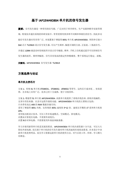
DA 转换及放大模块
图 1:DA 转换及放大模块
DA 转换方案选择 方案 1:串行 DAC 转换芯片 TLC5615。TLC5615 是一个串行 10 位 DAC 芯片,性能优于早期 电流输出型 DAC,只通过 3 根串行总线就可以完成 10 位数据的串行输入,易于和工业标准 的微处理器或微处理器接口,适用于电池供电的测试仪表、移动电话,也适用于数字失调与 增益调整以及工业控制场合。其主要参数如下: 单 5V 电源工作; 3 线串行接口; 高阻抗基准输入端; DAC 输出的最大电压为 2 倍基准输入电压; 上电时内部自动复位; 微功耗,最大功耗唯爱 1.75mw; 转换速率快,更新率为 1.21MHz; 方案 2:并行 DAC 转换芯片 DAC0832。DAC0832 是 8 分辨率 D/A 转换集成芯片,芯片由 8 位 输入锁存器、8 位 DAC 寄存器、8 位 D/A 转换电路及转换控制电路构成。其主要参数如下: 分辨率为 8 位; 电流稳定时间为 1us; 单电源供电(+5V~+15V); 8 位并行数据输入; 方案比较说明:并行 DAC 转换时间短,反应速度快,但芯片引脚多,体积较大,与单片机的
ILD621中文资料
750
°C/W
6.8
pF
VCE=5 V, f=1 MHz
10
100
nA
VCE=24 V
2
50
µA
TA=85°C, VCE=24 V
500
°C/W
1 to 1
3 to 1
IF=5 mA, VCE=5 V
60
%
50
80
600
%
0.4
V
IF=1 mA, VCE=0.4 V IF=5 mA, VCE=5 V IF=8 mA, ICE=2.4 mA
CCM CI-O RS
Switching Times Figure 1. Non-saturated switching timing
IF
Min. Typ. Max. Unit Condition
1
1.15 1.3
V
IF=10 mA
0.01 10
µA
VR=6 V
40
pF
VF=0 V, f=1 MHz
Detector
Collector-Emitter Reverse Voltage ...................70 V Collector Current .......................................... 50 mA Collector Current (t <1 ms)..........................100 mA Power Dissipation.......................................150 mW Derate from 25°C .................................... –2 mW/°C
zdk615-4-12单开道岔

14°02′10″ 11°18′36″ 9°27′36″ 18°26′06″ 18°26′06″ 18°26′07″ 18°26′08″ 18°26′09″ 18°26′10″ 14°02′10″ 14°02′11″ 11°18′36″ 11°18′37″ 9°27′44″ 9°27′45″ 14°02′10″ 14°02′11″ 11°18′36″ 11°18′37″ 9°27′44″ 9°27′45″ 14°02′10′ 14°02′11′ 11°18′36″ 11°18′37″ 9°27′44″ 9°27′45″
主
11 12 13 14 15 16 17 18 19 20 21 22 23 24 25 26 27 28 29 30 31 32 33 34 35 36 37
单开道岔 单开道岔 单开道岔 对称道岔 对称道岔 对称道岔 对称道岔 对称道岔 对称道岔 渡线道岔 渡线道岔 渡线道岔 渡线道岔 渡线道岔 渡线道岔 渡线道岔 渡线道岔 渡线道岔 渡线道岔 渡线道岔 渡线道岔 渡线道岔 渡线道岔 渡线道岔 渡线道岔 渡线道岔 渡线道岔
15283564825
7300 8300 10100 4814 5064 4964 5224 5115 5375 12123 12923 14137 15137 17147 18347 12523 13323 14537 15537 17747 18947 12920 13720 14934 15934 18344 19544
1562 1734 8400 606 629 940 957 1214 1253 1466 1542 1692 1734 1959 2013 2160 2323 2478 2581 2992 3129 2919 3229 3214 3476 3931 4243
VISHAY ILD615 ILQ615 数据手册

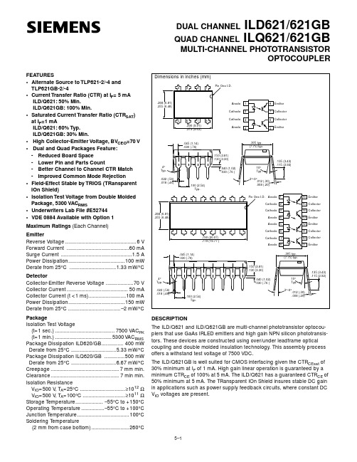
Document Number Optocoupler, Phototransistor Output (Dual, Quad Channel)Features•Identical Channel to Channel Footprint •Dual and Quad Packages Feature: - Reduced Board Space - Lower Pin and Parts Count- Better Channel to Channel CTR Match - Improved Common Mode Rejection•Isolation Test Voltage from Double Molded Pack-age, 5300 V RMS•Lead-free component•Component in accordance to RoHS 2002/95/EC and WEEE 2002/96/ECAgency Approvals•UL1577, File No. E52744 System Code H or J, Double Protection •CSA 93751•BSI IEC60950 IEC60965•DIN EN 60747-5-2 (VDE0884)DIN EN 60747-5-5 pending Available with Option 1DescriptionThe ILD615/ ILQ615 are multi-channel phototransis-tor optocouplers that use GaAs IRLED emitters and high gain NPN phototransistors. These devices are constructed using over/under leadframe optical cou-pling and double molded insulation technology result-ing a withstand test voltage of 7500 VAC PEAK and a working voltage of 1700 V RMS .The binned min./max. and linear CTR characteristics make these devices well suited for DC or AC voltage detection. Eliminating the phototransistor base con-nection provides added electrical noise immunity from the transients found in many industrial control envi-ronments.Because of guaranteed maximum non-saturated and saturated switching characteristics, the ILD615/ILQ615 can be used in medium speed data I/O and control systems. The binned min./max. CTR specifi-cation allow easy worst case interface calculations forboth level detection and switching applications. Inter-facing with a CMOS logic is enhanced by the guaran-teed CTR at I F = 1.0 mA. Document Number 83652ILD615/ ILQ615Vishay Semiconductors Order InformationFor additional information on the available options refer to Option Information.PartRemarksILD615-1CTR 40 - 80 %, Dual Channel, DIP-8ILD615-2CTR 63 - 125 %, Dual Channel, DIP-8ILD615-3CTR 100 - 200 %, Dual Channel, DIP-8ILD615-4CTR 160 - 320 %, Dual Channel, DIP-8ILQ615-1CTR 40 - 80 %, Quad Channel, DIP-16ILQ615-2CTR 63 - 125 %, Quad Channel, DIP-16ILQ615-3CTR 100 - 200 %, Quad Channel, DIP-16ILQ615-4CTR 160 - 320 %, Quad Channel, DIP-16ILD615-1X007CTR 40 - 80 %, Dual Channel, SMD-8 (option 7)ILD615-2X006CTR 63 - 125 %, Dual Channel, DIP-8 400 mil (option 6)ILD615-2X009CTR 63 - 125 %, Dual Channel, SMD-8 (option 9)ILD615-3X006CTR 100 - 200 %, Dual Channel, DIP-8 400 mil (option 6)ILD615-3X007CTR 100 - 200 %, Dual Channel, SMD-8 (option 7)ILD615-3X009CTR 100 - 200 %, Dual Channel, SMD-8 (option 9)ILD615-4X006CTR 160 - 320 %, Dual Channel, DIP-8 400 mil (option 6)ILD615-4X009CTR 160 - 320 %, Dual Channel, SMD-8 (option 9)ILQ615-1X009CTR 40 - 80 %, Quad Channel, SMD-16 (option 9)ILQ615-2X007CTR 63 - 125 %, Quad Channel, SMD-16 (option 7)ILQ615-3X006CTR 100 - 200 %, Quad Channel, DIP-16 400 mil (option 6)ILQ615-3X009CTR 100 - 200 %, Quad Channel, SMD-16 (option 9)ILQ615-4X007CTR 160 - 320 %, Quad Channel, SMD-16 (option 7)ILQ615-4X009CTR 160 - 320 %, Quad Channel, SMD-16 (option 9)ILD615/ ILQ615Document Number 83652Vishay SemiconductorsAbsolute Maximum RatingsT amb = 25°C, unless otherwise specifiedStresses in excess of the absolute Maximum Ratings can cause permanent damage to the device. Functional operation of the device is not implied at these or any other conditions in excess of those given in the operational sections of this document. Exposure to absolute Maximum Rating for extended periods of the time can adversely affect reliability.InputOutputCouplerParameterTest conditionSymbol Value Unit Reverse voltage V R 6.0V Forward current I F 60mA Surge current I FSM 1.5A Power dissipation P diss100mW Derate linearly from 25°C1.33mW/°CParameterTest conditionSymbol Value Unit Collector-emitter breakdown voltageBV CEO 70V Emitter-collector breakdown voltageBV ECO 7.0V Collector currentI C 50mA t < 1.0 msI C 100mA Power dissipation P diss150mW Derate linearly from 25°C2.0mW/°CParameterTest conditionSymbol Value Unit Storage temperature T stg - 55 to + 150°C Operating temperature T amb - 55 to + 100°C Junction temperature T j 100°C Soldering temperature 2.0 mm distance from case bottomT sld260°C Package power dissipation, ILD615400mW Derate linearly from 25°C 5.33mW/°C Package power dissipation, ILQ615500mW Derate linearly from 25°C 6.67mW/°C Isolation test voltage t = 1.0 sec.V ISO5300V RMS Creepage ≥ 7.0mm Clearance≥ 7.0mm Isolation resistanceV IO = 500 V, T amb = 25°C R IO ≥ 1012ΩV IO = 500 V, T amb = 100°CR IO≥ 1011Ω Document Number 83652ILD615/ ILQ615Vishay Semiconductors Electrical CharacteristicsT amb = 25°C, unless otherwise specifiedMinimum and maximum values are testing requirements. Typical values are characteristics of the device and are the result of engineering evaluation. Typical values are for information only and are not part of the testing requirements.InputOutputCouplerCurrent Transfer RatioParameterTest conditionSymbol Min Typ.Max Unit Forward voltage I F = 10 mA V F 1.0 1.15 1.3V Breakdown voltage I R = 10 µA V BR 6.030V Reverse current V R = 6.0 VI R 0.0110µA CapacitanceV R = 0 V, f = 1.0 MHzC O 25pF Thermal resistance, junction to leadR THJL750K/WParameterTest conditionSymbol MinTyp.MaxUnit Collector-emitter capacitance V CE = 5.0 V, f = 1.0 MHz C CE 6.8pF Collector-emitter leakage current, -1, -2V CE = 10 V I CEO 2.050nA Collector-emitter leakage current, -3, -4V CE = 10 V I CEO 5.0100nA Collector-emitter breakdown voltageI CE = 0.5 mA BV CEO 70V Emitter-collector breakdown voltageI E = 0.1 mABV ECO 7.0V Thermal resistance, junction to leadR THJL500K/WPackage transfer characteristics Channel/Channel CTR matchI F = 10 mA, V CE = 5.0 VCTRX/CTRY1 to 12 to 1ParameterTest conditionSymbol MinTyp.MaxUnit Capacitance (input-output)V IO = 0 V, f = 1.0 MHz C IO 0.8pF Insulation resistance V IO = 500 V, T A = 25°CR S10121014ΩChannel to channel isolation500VACParameterTest conditionPart Symbol MinTyp.MaxUnit Current Transfer Ratio(collector-emitter saturated)I F = 10 mA, V CE = 0.4 VILD615-1 ILQ615-1CTR CEsat 25%ILD615-2 ILQ615-2CTR CEsat 40%ILD615-3 ILQ615-3CTR CEsat 60%ILD615-4 ILQ615-4CTR CEsat100%ILD615/ ILQ615Document Number 83652Vishay SemiconductorsSwitching Non-saturatedSwitching SaturatedCommon Mode Transient ImmunityCurrent Transfer Ratio (collector-emitter)I F = 10 mA, V CE = 5.0 V ILD615-1 ILQ615-1CTR CE 406080%I F = 1.0 mA, V CE = 5.0 V ILD615-2 ILQ615-2CTR CE 1330%I F = 10 mA, V CE = 5.0 V ILD615-3 ILQ615-3CTR CE 6380125%I F = 1.0 mA, V CE = 5.0 V ILD615-4 ILQ615-4CTR CE 2245%I F = 10 mA, V CE = 5.0 V ILD615-1 ILQ615-1CTR CE 100150200%I F = 1.0 mA, V CE = 5.0 V ILD615-2 ILQ615-2CTR CE 3470%I F = 10 mA, V CE = 5.0 V ILD615-3 ILQ615-3CTR CE 160200320%I F = 1.0 mA, V CE = 5.0 VILD615-4 ILQ615-4CTR CE5690%ParameterTest conditionPart Symbol Min Typ.Max Unit Parameter CurrentTurn-on timeRise timeTurn-off timeFall timePropagationH-LPropagationL-HTest condition V CC = 5.0 V, R L = 75 Ω, 50 % of V PP Symbol I F t on t r t off t f t PHL t PLH Unit mA µs µs µs µs µs µs ILD615-1103.02.02.32.01.12.5Parameter CurrentTurn-on timeRise timeTurn-off timeFall timePropagationH-LPropagationL-HTest condition V CC = 5.0 V, R L = 1.0 k Ω, V TH = 1.5 V Symbol I F t on t r t off t f t PHL t PLH Unit mA µs µs µs µs µs µs ILD615-1 ILQ615-120 3.0 2.01811 1.68.6ILD615-2 ILQ615-210 4.3 2.82514 2.67.2ILD615-3 ILQ615-310 4.3 2.82514 2.67.2ILD615-4 ILQ615-45.06.04.625155.47.4ParameterTest conditionSymbol MinTyp.MaxUnit Common mode rejection output high V CM = 50 V P-P , R L = 1.0 k Ω, I F = 0 mA CM H 5000V/µs Common mode rejection output low V CM = 50 V P-P , R L = 1.0 k Ω, I F = 10 mA CM L 5000V/µs Common mode coupling capacitanceC CM0.01pF Document Number 83652ILD615/ ILQ615Vishay SemiconductorsTypical Characteristics (Tamb = 25 °C unless otherwise specified)Figure 1. Non-saturated Switching Timing Figure 2. Saturated Switching Timing Figure 3. Non-saturated Switching Timing iild615_01O =5V75ΩF =DF I F =iild615_02O=5Viild615_03V I onoffFigure 4. Saturated Switching TimingFigure 5. Maximum LED Current vs. Ambient TemperatureFigure 6. Maximum LED Power Dissipationiild615_04IV O-60-40-20020406080100120100806040020Ta -Ambient Temperature -°CI F -M a x i m u m L E D C u r r e n t -m Aiild615_05iild615_06-60-40-2002040608010020010050Ta -Ambient Temperature -°CP L E D -L E D P o w e r -m W150ILD615/ ILQ615Document Number 83652Vishay SemiconductorsFigure 7. Forward Voltage vs. Forward Current Figure 8. Peak LED Current vs. Pulse Duration, TauFigure 9. Maximum Detector Power Dissipationiild615_07IF -Forward Current -mA100101.10.70.80.91.01.11.21.31.4V F -F o r w a r d V o l t a g e -Viild615_0810-610-510-410-310-210-110010110000100010010t -LED Pulse Duration -sI f (p k )-P e a k L E D C u r r e n t -m Aiild615_0950Ta -Ambient Temperature -°CP D E T -D e t e c t o r P o w e r -m WFigure 10. Maximum Collector Current vs. Collector VoltageFigure 11. Normalization Factor for Non-saturated and SaturatedCTR vs. I FFigure 12. Normalization Factor for Non-saturated and SaturatedCTR vs. I Fiild615_10.1101001000100101.1V CE -Collector-Emitter Voltage -VI C E -C o l l e c t o r C u r r e n t -m A1iild615_11C T R N F -N o r m a l i z e d C T R F ac t o r.11101002.01.51.00.50.0I F -LED Current -mAiild615_12C T R N F -N o r m a l i z e d C T R F a ct o r.11101002.01.51.00.50.0I F -LED Current -mA Document Number 83652ILD615/ ILQ615Vishay SemiconductorsFigure 13. Normalization Factor for Non-saturated and SaturatedCTR vs. I FFigure 14. Normalization Factor for Non-saturated and SaturatedCTR vs. I FFigure 15. Collector-Emitter Current vs. Temperature and LEDCurrentiild615_13C T R N F -N o r m a l i z e d C T R F a c t o r.11101002.01.51.00.50.0I F -LED Current -mAiild615_14C T R N F -N o r m a l i z e d C TR F a c t o r.11101002.01.51.00.50.0I F -LED Current -mAiild615_15605030201005101520253035I F -LED Current -mAI C E -C o l l e c t o r C u r r e n t -m A40Figure 16. Collector Emitter Leakage vs. TemperatureFigure 17. -1, Propagation Delay vs. Collector Load ResistorFigure 18. -2, -3, Propagation Delay vs. Collector Load Resistoriild615_161010101010101010-2-1012345T A -Ambient Temperature -°CI C E O -C o l l e c t o r -E m i t t e r -n Aiild615_17R L -Load Resistor -k Ω100101.111010010001.01.52.04.0t p L H -P r o p a g a t i o n L o w -H i g h µst p H L -P r o p a g a t i o n H i g h -L o w µs2.53.03.5iild615_18R L -Collector Load Resistor -k Ω100101.111010010001.01.52.02.5t p L H -P r o p a g a t i o n L o w -H i g h µst p H L -P r o p a g a t i o n H i g h -L o w µsILD615/ ILQ615Document Number 83652Vishay SemiconductorsPackage Dimensions in Inches (mm)iild615_19R L -Collector Load Resistor -k Ω100101.111010010001.01.52.02.5t p L H -P r o p a g a t i o n L o w -H i g h µst p H L -P r o p a g a t i o n H i g h -L o w µsFigure 19. -4, Propagation Delay vs. Collector Load Resistor Document Number 83652ILD615/ ILQ615Vishay SemiconductorsPackage Dimensions in Inches (mm)ILD615/ ILQ615Document Number 83652Rev. 1.3, 19-Apr-04Vishay Semiconductors 11Ozone Depleting Substances Policy StatementIt is the policy of Vishay Semiconductor GmbH to 1.Meet all present and future national and international statutory requirements.2.Regularly and continuously improve the performance of our products, processes, distribution andoperatingsystems with respect to their impact on the health and safety of our employees and the public, as well as their impact on the environment.It is particular concern to control or eliminate releases of those substances into the atmosphere which are known as ozone depleting substances (ODSs).The Montreal Protocol (1987) and its London Amendments (1990) intend to severely restrict the use of ODSs and forbid their use within the next ten years. Various national and international initiatives are pressing for an earlier ban on these substances.Vishay Semiconductor GmbH has been able to use its policy of continuous improvements to eliminate the use of ODSs listed in the following documents.1.Annex A, B and list of transitional substances of the Montreal Protocol and the London Amendments respectively2.Class I and II ozone depleting substances in the Clean Air Act Amendments of 1990 by the Environmental Protection Agency (EPA) in the USA3.Council Decision 88/540/EEC and 91/690/EEC Annex A, B and C (transitional substances) respectively.Vishay Semiconductor GmbH can certify that our semiconductors are not manufactured with ozone depleting substances and do not contain such substances.We reserve the right to make changes to improve technical designand may do so without further notice.Parameters can vary in different applications. All operating parameters must be validated for each customer application by the customer. Should the buyer use Vishay Semiconductors products for any unintended or unauthorized application, the buyer shall indemnify Vishay Semiconductors against all claims, costs, damages, and expenses, arising out of, directly or indirectly, any claim of personaldamage, injury or death associated with such unintended or unauthorized use.Vishay Semiconductor GmbH, P.O.B. 3535, D-74025 Heilbronn, GermanyTelephone: 49 (0)7131 67 2831, Fax number: 49 (0)7131 67 2423。
CA 6155多功能电气设备检测仪说明书

C.A 6155IEC 60204第五版VDE 0701/0702便携式电气设备,机械和开关柜等电子安全测试适用千标准或个性化需求的预编程测试次序超大存储容量允许用户存放最多6000组测试值标配有数据处理和报告生成软件带有直观用户界面和每项功能文字帮助说明的大型背光式图形显示器内置键盘能够快速简易自定义测量值记录多功能电气设备检测仪规格介电强度测试测试电压电流限制1 O OOV / 1890V / 2500V 0.1至100mA (1890V / 2500V) 0.1至200mA I 1 O OOV IHV/电源的lmax 计时器200V A2. 3_ 5_ 10_ 30s绝缘电阻测蛋测试电压呈程计时器连续性测试旦程Zs回路测歪(不带RCD跳闸)程250 / 500VDC 最高至200MO 5. 10. 30. 60. 120 s精度lk 计算0.00至1.999fl 士(5%读数+10个字)0.00至230 kA测试电流高电流Zs回路测皂0 01至1.99n 0.20/10A 测试电压<9V测试电流登程精度lk 计算6.5A 0.00至1.999fl 土(5%读数+5个宇)0.00至230 kAZi回路测昼测试电流贵程精度lk 计算 6.5A 0.00至1.9990 ±(5%读数+5个字)0 00至199kA计时器 5. 10. 30. 60. 120. 180 s泄漏电流测登代替法差分法精度0.00至19.99mA 0.00至9.99mA士{5%读数+5个字)电压I频率0至550V / 14.0至499.9Hz相序检测电压频率100至550VAC 14至500Hz接触泄,届龟流测至程精度60V放电时间测歪电压范围(峰值10.00至2.50mA土(5%读数+3个字)时间范匣0至550V 0至10s其它规格RS232功能测试视在功率0.00至400 k VA电源残极性测试1个连接口用千条形码I无线射频识别读取器+1个接口用于打印机/PC1个接口用于打印机/PC全功能都可用是6000个存储单元电流钳的龟流测霍坚堡登软件标配附送0.00 mA至24.9A电源PRC D测试口径测试电流230V I 50-60 Hz10. 15、30mA 功能标准0.5xlt>n. lt>n. 5xlt,.n其它自动P RCD 测试VOE 701 702 / I EC / 60204 Ed 5 / I EC / 60439 / I EC 61439RCD 测试口径测试电流电流类型RCD 类型测试类型Uc 接触电压测贵其它10, 30, 100、300,500、1000mA 0.5xlt.n, lt.n, 2xlt.n, 5xlt.nAC /A IEC 61010-1 / I EC /61557 (第1. 2. 3_ 4. 6_ 7和10部分)—般l选择性步进l脉冲电气安全性CAT II /300V是尺寸/重量自动RCD 测试标准33.5 cm x 16.0 cm x 33.5 cm -8.4 kg订购�C.A 6155 .............................................................. P 01146001随便携包配送附件包含:—1x高压测试探棒—1x电源插头测试线—1x分离导线测试电缆—1x红色1.5m长导线—1x黑色1.5m长导线—1x绿色1.5m长导线—1x红色4m长导线-4x测试探棒—3x鍔鱼夹—1x五国语言操作手册—1xUS B连接线—1xRS 232连接线—数据传输软件厂。
- 1、下载文档前请自行甄别文档内容的完整性,平台不提供额外的编辑、内容补充、找答案等附加服务。
- 2、"仅部分预览"的文档,不可在线预览部分如存在完整性等问题,可反馈申请退款(可完整预览的文档不适用该条件!)。
- 3、如文档侵犯您的权益,请联系客服反馈,我们会尽快为您处理(人工客服工作时间:9:00-18:30)。
• UL Approval #E52744
• VDE #0884 Available with Option 1
Maximum Ratings (Each Channel)
Because of guaranteed maximum non-saturated and saturated switching characteristics, the ILD/Q615 can be used in medium speed data I/O and control systems. The binned min./max. CTR specification allow easy worst case interface calculations for both level detection and switching applications. Interfacing with a CMOS logic is enhanced by the guaranteed CTR at an IF=1 mA.
• Guaranteed CTR at IF=1 mA ILD/Q615-1: 13% Min. ILD/Q615-2: 22% Min. ILD/Q615-3: 34% Min. ILD/Q615-4: 56% Min.
• High Collector-Emitter Voltage BVCEO=70 V • Dual and Quad Packages Feature:
The binned min./max. and linear CTR characteristics combined with the TRIOS (TRansparent IOn Shield) field-effect process make these devices well suited for DC or AC voltage detection. Eliminating the phototransistor base connection provides added electrical noise immunity from the transients found in many industrial control environments.
.100 (2.54) Typ.
10° Typ.
.135 (3.43) .115 (2.92)
3°) .255 (6.48)
.790 (20.07) .779 (19.77 )
.045 (1.14) .030 (.76)
4° Typ.
- Reduced Board Space
- Lower Pin and Parts Count
- Better Channel to Channel CTR Match
- Improved Common Mode Rejection
• Field-Effect Stable by TRIOS (TRansparent IOn Shield)
(2 mm distance from case bottom) ........... 260°C Package Power Dissipation, ILD615.......... 400 mW
Derate Linearly from 25°C.................. 5.33 mW/°C Package Power Dissipation, ILQ615 ......... 500 mW
Emitter
Reverse Voltage ................................................ 6 V Forward Current ........................................... 60 mA Surge Current .................................................1.5 A Power Dissipation ...................................... 100 mW Derate Linearly from 25°C ................... 1.33 mW/°C
See Appnote 45, “How to Use Optocoupler Normalized Curves.”
5–1
元器件交易网
Characteristics, TA=25°C
Emitter Forward Voltage Breakdown Voltage Reverse Current Capacitance Thermal Resistance, Junction to Lead Detector Capacitance Collector-Emitter Leakage Current, -1, -2 Collector-Emitter Leakage Current, -3, -4 Collector-Emitter Breakdown Voltage Emitter-Collector Breakdown Voltage Thermal Resistance, Junction to Lead Package Transfer Characteristics Channel/Channel CTR Match ILD/Q615-1 Saturated Current Transfer Ratio Current Transfer Ratio Current Transfer Ratio ILD/Q615-2 Saturated Current Transfer Ratio Current Transfer Ratio Current Transfer Ratio ILD/Q615-3 Saturated Current Transfer Ratio Current Transfer Ratio Current Transfer Ratio ILD/Q615-4 Saturated Current Transfer Ratio Current Transfer Ratio Current Transfer Ratio Isolation and Insulation Common Mode Rejection, Output High Common Mode Rejection, Output Low Common Mode Coupling Capacitance Package Capacitance Insulation Resistance Channel to Channel Isolation
VIO=500 V, TA=25°C ............................... ≥1012 Ω VIO=500 V, TA=100°C ............................. ≥1011 Ω
DUAL CHANNEL ILD615 QUAD CHANNEL ILQ615
.150 (3.81) .130 (3.30)
.305 Typ. (7.75) Typ.
.040 (1.02) .030 (.76 )
10° Typ.
.135 (3.43) .115 (2.92)
3°–9°
.012 (.30) .008 (.20)
DESCRIPTION
The ILD/Q615 are multi-channel phototransistor optocouplers that use GaAs IRLED emitters and high gain NPN phototransistors. These devices are constructed using over/under leadframe optical coupling and double molded insulation technology resulting a Withstand Test Voltage of 7500 VACPEAK and a Working Voltage of 1700 VACRMS.
Package Storage Temperature................... –55°C to +150°C Operating Temperature ............... –55°C to +100°C Junction Temperature.................................... 100°C Soldering Temperature
Derate Linearly from 25°C................. 6.67 mW/°C Isolation Test Voltage (t=1 sec.)........ 5300 VACRMS Creepage ............................................... 7 mm min. Clearance............................................... 7 mm min. Isolation Resistance
.045 (1.14) .150 (3.81) .030 (.76) .130 (3.30)
8 Collector 7 Emitter 6 Collector 5 Emitter
.305 Typ. (7.75) Typ.
T4y°p.
.022 (.56) .018 (.46)
.040 (1.02) .030 (.76 )
PHOTOTRANSISTOR OPTOCOUPLER
Dimensions in inches (mm)