Fe-Si for Li battery[1]
硅烷添加剂在锂离子电池电解液中的应用
第49卷第1期 2021年1月硅 酸 盐 学 报Vol. 49,No. 1 January ,2021JOURNAL OF THE CHINESE CERAMIC SOCIETY DOI :10.14062/j.issn.0454-5648.20200377硅烷添加剂在锂离子电池电解液中的应用徐 菲1,2,李世友1,2,赵冬妮1,2,杨 莉1,2,王 洁1,2(1. 兰州理工大学石油化工学院,兰州 730050;2. 甘肃省锂离子电池电解液材料工程实验室,兰州 730050)摘 要:硅烷添加剂因具有高热稳定性、低可燃性、无毒性、高电导率和高分解电压等优点,近年来成为了锂离子电池电解液新型添加剂的研究热点。
本文重点介绍了在硅烷电解液添加剂中Si—O 结构、Si—N 结构所发挥的作用以及机理,最后对硅烷添加剂的进一步研究趋势和应用前景进行了展望。
关键词:锂离子电池;电解液;硅烷添加剂;机理中图分类号:TM911.3 文献标志码:A 文章编号:0454–5648(2021)01–0161–06 网络出版时间:2020–12–17Application of Silane Additive in Electrolyte of Lithium Ion BatteryXU Fei 1,2, LI Shiyou 1,2, ZHAO Dongni 1,2, YANG Li 1,2, WANG Jie 1,2(1. College of Petrochemical Technology, Lanzhou University of Technology, Lanzhou 730050, China; 2. Gansu Engineering Laboratory of Electrolyte Material for Lithium-ion Battery, Lanzhou 730050, China)Abstract: Silane additives have attracted recent attention as novel electrolytes for lithium-ion batteries due to their high thermal stability, low flammability, non-toxicity, high conductivity and high decomposition voltage. The role and mechanism of Si—O and Si—N structure in silane electrolyte additives were mainly reviewed. In addition, the further research trends and application prospects of silane additives were also prospected.Keywords: lithium-ion battery; electrolyte; silane additive; mechanism锂离子电池因具有高电压、高容量、长寿命等显著优点,已被广泛应用于消费类电子产品、新能源汽车、航空航天及军事装备等领域[1]。
硫化亚铁锂硫电池-概述说明以及解释

硫化亚铁锂硫电池-概述说明以及解释1.引言1.1 概述硫化亚铁锂电池是一种新型的高性能锂硫电池,其以硫化亚铁(FeS2)作为正极材料,锂金属或锂合金作为负极材料。
相比传统的锂离子电池,硫化亚铁锂电池具有更高的能量密度和较低的成本,被认为是未来可持续能源存储和电动汽车领域的重要技术之一。
硫化亚铁锂电池的工作原理基于锂-硫反应,通过在正极和负极之间嵌入锂离子来存储和释放电能。
当电池充电时,锂离子从负极向正极移动,在正极的硫材料中发生反应形成Li2S2或Li2S的锂-硫化物。
在放电过程中,锂离子从正极释放出来,重新嵌入到负极中,使得硫材料逐渐还原为硫化物,同时释放出电能。
硫化亚铁锂电池具有多种优势。
首先,硫化亚铁作为正极材料具有较高的比容量和较低的成本,能够提高电池的能量密度和经济效益。
其次,硫化亚铁锂电池具有良好的循环寿命和循环稳定性,能够实现长时间的充放电循环而不损失性能。
此外,硫化亚铁锂电池的工作温度范围宽广,能够在较低温度下仍然保持良好的性能。
这些优势使得硫化亚铁锂电池在可再生能源储存和电动车辆领域具有广泛的应用前景。
本文将详细介绍硫化亚铁锂电池的原理和优势,并对其应用前景进行展望。
深入了解和掌握硫化亚铁锂电池的特点和性能,有助于我们更好地利用和发展这一高性能能源储存技术,推动清洁能源的发展和应用。
1.2 文章结构文章结构部分主要介绍本篇文章的组织架构和各个章节的内容概述。
本文总共分为引言、正文和结论三个部分。
在引言部分,本文首先概述了硫化亚铁锂硫电池的背景和基本概念,以引发读者的兴趣。
接着,文章结构部分对整篇文章进行了概括,为读者提供了整体的框架。
正文部分是本文的核心部分,主要介绍了硫化亚铁锂电池的原理和优势。
在2.1节中,详细解释了硫化亚铁锂电池的工作原理,包括其反应过程和电化学反应机制。
2.2节则着重介绍了硫化亚铁锂电池相较于传统锂离子电池的优势,包括高能量密度、长循环寿命和低成本等方面。
硅负极锂离子电池
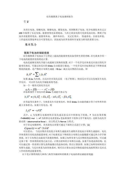
从中可以看出硅材料做负极材料的理论储能密度高达4200mAh/g,是所有负极材料中储能密度最高的,远超现在的商业石墨负极电极。
研究进展
面临的问题
电池实际上能够实现的能量密度显著低于基于活性物质计算的理论能量密度。对于硅负极锂离子电池来说这个问题尤为严重,这是因为在充放电循环中,由于锂离子不断地嵌入和脱出,硅的体积变化可以达到400%[3],由此会产生一系列的问题,硅颗粒粉碎和材料的断裂会破坏电极结构,使得导电变差引起容量下降,电化学循环过程中,沿电极厚度方向的电化学反应导致的不均匀极化会导致电极发生层状破裂与剥离,进而出现导电网络崩溃以及电极失效。同时由于体积在脱嵌和嵌入锂离子的过程中体积变化过大,导致电极表面的SEI膜不断的生成和破损,结果会使得SEI不断增加,消耗活性物质,使得电池的容量下降。[4]
[8]D.Chen,X.Mei,G.Ji,M.Lu,J.Xie,J.Lu and J.Y.Lee,Reversible lithium-ion storage in silver-treated nanoscale hollow porous silicon particles,Angew Chem.Int.Ed.,2012,5 1:2409.2413
Mullane[12]等人利用类似的VLS机理,改用不同的催化剂(Sn)与硅源(苯基硅烷),通过CVD万法合成了硅纳米线,由于sn本身也可以作为锂离子电池负极材料,因此阻sn为催化剂合成的硅纳米线在充放电循环过程中,sl与sn均参与循环。这种方法合成的硅纳米线,在0.5C电流密度下(活陛物质的质量计算为Si与sn的总质量,0.5c电流密度为1245 mAh/g),50个充放电循环后依然具有1078mAh/g的比容量.
磷酸铁锂电化学反应方程式
磷酸铁锂电化学反应方程式磷酸铁锂(LiFePO4)是一种常见的锂离子电池正极材料,具有高容量、高循环寿命和较高的安全性。
在充放电过程中,磷酸铁锂发生着一系列电化学反应。
充电过程中,锂离子从电源的负极(如石墨)通过电解液中的传导剂(如碳酸锂)进入正极材料磷酸铁锂的结构中。
此时,磷酸铁锂结构中的Fe(金属离子)与Li(锂离子)发生置换反应,形成锂含量较高的亚相锂磷酸铁(Li[1-x]FePO4)。
具体反应示例如下:LiFePO4 + Li+ + e- --> Li[1-x]FePO4在充电的过程中,正极材料磷酸铁锂的结构发生了改变,锂离子进入了磷酸铁锂的结构中,降低了Fe的含量,因此被称为锂离子嵌入反应。
这个嵌入反应是可逆的,即充电和放电过程中可以反复发生。
放电过程中,锂离子从正极材料的结构中脱嵌出来,再通过电解液中的传导剂返回至电源的负极,释放出电能。
此时,锂离子从亚相锂磷酸铁(Li[1-x]FePO4)中脱出,反应式如下:Li[1-x]FePO4 --> LiFePO4 + Li+ + e-这是一个锂离子脱嵌反应。
可以看出,充放电过程中,磷酸铁锂的结构发生了变化,锂离子在正极材料和电解液之间穿梭,完成了电池的充放电。
磷酸铁锂电池的充放电反应还受到其他因素的影响,如电极材料的导电性、电解液的反应性等。
磷酸铁锂电池还具有较高的容量衰减率,在循环充放电过程中容量会逐渐降低,主要原因是磷酸铁锂颗粒中的内部电阻增加,并且锂离子嵌入和脱嵌反应过程中的极化现象。
总的来说,磷酸铁锂电池的电化学反应方程式可以简化为以下两个反应:充电过程:LiFePO4 + Li+ + e- --> Li[1-x]FePO4放电过程:Li[1-x]FePO4 --> LiFePO4 + Li+ + e-随着锂离子电池技术的不断发展,磷酸铁锂电池在电动汽车、储能等领域得到了广泛应用,并且具有良好的前景。
静电纺丝制备富锂锰基锂电正极材料及其性能
静电纺丝制备富锂锰基锂电正极材料及其性能李永亮;马定涛;张培新【摘要】通过静电纺丝技术制备了具有一维管状结构的Li1.2Mn0.54Ni0.13Co0.13O2正极材料,研究了煅烧温度对电极材料表面形貌和电化学性能的影响.结果表明,煅烧温度为850 ℃时所制产物具有较好的离子扩散性能,在50 mAh·g-1的电流密度下首次放电比容量为249.5 mAh·g-1,50次循环后的容量保持率为87%,表现出较高的放电比容量和较好的循环稳定性.%One-dimensional tube-like structure of Li1.2Mn0.54Ni0.13Co0.13O2 cathode material was synthesized by electrospinning.The effects of calcination temperature on the morphology and electrochemical performance of the battery cathode material were studied.The results show that the sample synthesized at 850 ℃ possesses a relatively high discharge capacity and good cyclic stability, which delivers 249.5 mAh·g-1 at the first cycle and remains 87% retention after 50 cycles at the current density of 50 mAh·g-1, owing to a relatively high ionic diffusion capability.【期刊名称】《深圳大学学报(理工版)》【年(卷),期】2017(034)002【总页数】6页(P132-137)【关键词】应用化学;静电纺丝;富锂锰基;管状结构;煅烧温度;电化学性能【作者】李永亮;马定涛;张培新【作者单位】深圳大学化学与环境工程学院,广东深圳518060;深圳大学化学与环境工程学院,广东深圳518060;深圳大学化学与环境工程学院,广东深圳518060【正文语种】中文【中图分类】O69随着经济快速发展,燃油轿车日益普及,汽车尾气排放导致的环境污染及石油过度消耗导致的能源危机,成为不得不面临的严竣问题.发展绿色无污染且具有高续航里程的电动轿车无疑是解决问题的有效途径,而高比容量正极材料的研究将是推动高能量密度锂离子电池发展的关键.目前,中国商业化的锂离子电池正极材料主要是磷酸铁锂与三元体系层状材料,尽管它们具有优异的循环稳定性,然而其理论比容量却不高.针对这一问题,寻找一种具有更高比容量的正极材料很有必要.其中,富锂锰基固溶体材料xLiMO2·(1-x)Li2MnO3(M表示Mn、Co和Ni等)的理论比容量可高达250 mA h·g-1以上,高于磷酸铁锂与三元层状材料,具有较好的应用前景.然而其不可逆的首次循环容量损失及循环过程中过渡金属层中的离子混排,导致其电化学循环性能难以满足实际需要[1-3].一维结构的纳米材料,由于具有比表面积大、长径比大和易功能化等优点,在能源研究领域具有较好的发展前景.然而,其常见的合成方法,如模板法和自组装法等,合成工艺复杂且成本较高,不利于进一步应用发展.静电纺丝是通过施加电压将纺丝溶液定向拉伸成丝,是一种用于构建一维结构纳米材料的简易技术.由于纺丝溶液分子级别的混合能够保证前驱体产物中离子的均匀分布,通过对于纺丝与煅烧工艺的调控,可有效用于制备高性能锂离子电池电极材料.基于前期研究结果[4-9],本研究采用静电纺丝技术,一步原位合成了具有空心管状结构的富锂锰基正极材料.这种结构在充放电过程中不仅为反应提供更多的活性位点,还可以大大缩短锂离子的传输扩散距离.同时,通过调节合成温度能有效提高充放电过程中的锂离子扩散系数,从而制备出电化学性能优异的正极材料.1.1 正极材料的制备① 分别将1.8 g的高分子聚丙烯腈(polyacrylonitrile, PAN)、1.2 mmol的醋酸锂、0.54 mmol的醋酸锰、0.13 mmol的醋酸镍与0.12 mmol的醋酸钴溶解于有机溶剂N, N-二甲基甲酰胺 (N, N-dimethylformamide, DMF)中,密封持续搅拌10 h后,得到混合均匀的溶液.② 将醋酸盐溶液缓慢地倒入PAN溶液中,密封继续搅拌12 h后得到混合均匀的纺丝溶液.静电纺丝过程主要参数为:高压电源13.5 kV、环境湿度30%、纺丝温度40 ℃、接收距离17 cm、滚筒转速800r/min.③ 将接收板上所得的无纺布膜从铝箔上揭出,在空气中,以5 ℃/min 的速率升温至280 ℃保温4 h,然后升温至目标温度,并保温5 h,即可得产物.1.2 材料表征采用X射线衍射仪(X-ray diffraction, XRD, 型号为Bruker D8 Advance)对产物的晶体结构进行分析(CuKα, 40 kV, 40 mA ).采用扫描电子显微镜(scanning electron microscope, SEM,型号为Hitachi S-3400N)与透射电子显微镜(transmission electron microscope, TEM,型号为Tecnai G2 F30)对产物的形貌结构进行表征.采用粉末X射线光电子能谱仪(X-ray photoelectron spectroscopy, XPS,型号为ESCALAB 250Xi)对产物表面的金属元素化合价态进行分析,并采用C1s =284.4 eV进行数据较正;使用XPS Peak软件进行数据拟合.1.3 电化学性能测试将产物、乙炔黑与黏结剂按质量比为8∶1∶1混合均匀,加入到N-甲基吡咯烷酮(N-methyl pyrrolidone, NMP)溶剂中,搅拌6 h得电极浆料.把所得浆料均匀涂覆在集流体铝箔表面,于120 ℃真空干燥8 h后冲成正极极片,并于手套箱中进行半电池封装.用蓝电测试系统进行电化学性能测试,充放电电压为2.0~4.8 V,在电化学工作站(CHI660A)中进行交流阻抗谱测试.图1为不同煅烧温度(800、850和900 ℃)所制的Li1.2Mn0.54Ni0.13Co0.12(LMNCO) 晶体结构衍射图.从图1可以看出,这3种产物的衍射峰基本一致,归属于m空间点群的α-NaFeO2结构.除此之外,在20°~24°间出现的几个弱衍射峰则归属于C2/m空间点群的单斜晶系Li2MnO3[10-14].一方面,随着煅烧温度的升高,可以发现(003)与(104)等晶面的衍射强度呈现上升趋势.文献[15-16]研究结果表明,当晶胞参数轴长c与轴长a的比值c/a>4.9时,富锂固溶体材料具有良好的层状结构.通过计算可知,上述3种产物(800、850和900 ℃)的c/a值分别为4.945 4、4.955 7和4.964 0,均具有良好的层状结构.另一方面,可用I(003)/I(104)比值表征过渡金属层中阳离子的混排程度,该值越大,则表明离子排布有序度越高,更有利于锂离子在晶格中的扩散传递[16-17].通过计算可知,上述3种产物(800、850和900 ℃)的I(003)/I(104)比值分别为1.598 7、1.609 4和1.605 8,即850 ℃和900 ℃产物阳离子排布有序度更好.图2分别为不同煅烧温度下所得产物的表面形貌图.其中,图2(a)为静电纺丝后所得前驱体无机盐-PAN纤维,可以看出纤维直径约为1 μm,分布比较均匀.图2(b)至(d)分别为800、850和900 ℃煅烧温度下所得产物的形貌图.从图2(b)至(d)中可以看出,随着煅烧温度逐渐升高,产物形貌发生了明显的变化.800 ℃时产物的形貌依然保持纤维状;而当煅烧温度升至850 ℃时,纤维结构发生断裂,产物具有明显的管状结构,该结构具有较高的反应比表面积,更有利于充放电过程中活性材料与电解液的接触;当煅烧温度升至900 ℃时,由于颗粒的过度生长,晶粒界面间的作用应力过大,从而导致一维结构发生崩塌,变成了许多团聚的二次颗粒.图3分别为800-LMNCO与850-LMNCO产物的TEM图像.由图3(a)和(c)可以看出,产物的边缘部分与中心部分呈现一定的亮度反差,表明该产物为管状结构,这与前面SEM观察结果一致.图3(b)和(d)为两种样品进一步放大后的透射电镜图,由图可知,管状结构是由许多纳米颗粒无序堆积形成.事实上,这种空心结构能够在充放电过程中为反应提供更多的活性点,且纳米尺寸的颗粒有利于大电流下锂离子的快速脱嵌.对于锂离子电池而言,充放电过程中锂离子的来回脱嵌主要依赖于金属元素的氧化还原反应驱动,所以有必要对其中的Mn、Ni和Co 3种金属元素进行化合价态分析.图4为850 ℃时制得产物的金属元素2pXPS图谱,所有曲线均用C1s (284.4 eV)进行了校正.图4(a)为测试范围内的全谱曲线.图4(b)和(d)分别为产物Mn 2p、Co 2p和Ni 2p的拟合图谱,拟合曲线与实验曲线基本吻合.从图4(b)中可以看出,Mn 2p图谱主要是由一个Mn 2p3/2(643.2 eV)主峰及相对应的Mn 2p1/2卫星峰组成,由文献[18-19]报道可知,它主要对应于Mn4+,即样品中的锰元素主要以+4价存在.类似地,Ni 2p3/2与Co 2p3/2图谱均为主峰(Co约为780.5 eV,Ni约为855.5 eV)及对应的卫星峰组成,分别对应于Co3+与Ni2+.综上分析可知,富锂锰基材料中的金属元素Mn、Co和Ni主要以+4、+3和+2化合价态存在.图5(a)为不同煅烧温度下所得产物在电流密度为50 mAh·g-1、电压范围为2.0~4.8 V的循环性能比较图.由图5(a)可知,相比另外两种产物,800 ℃时合成产物的循环性明显较差.这可能是受煅烧温度的影响,颗粒的结晶度和晶体中阳离子的排列有序度较低所导致.而煅烧温度为850和900 ℃的产物虽然首次放电比容量相近,分别为249.5和251.2 mAh·g-1,但经过50次循环后,它们的放电比容量分别为217.6和210.8 mAh·g-1,容量保持率分别为87%和84%.此外,由图5(b)可知,随着充放电倍率的增加,850 ℃时产物表现出最佳的大倍率充放电性能.由此可见,煅烧温度不仅对产物的形貌结构有较大影响,且对电化学性能影响也较大.事实上,反应发生的动力学难易程度对于锂离子电池材料电化学性能的发挥起着制约作用.其中,反应过程中的锂离子扩散系数是衡量电极材料电化学性能的最重要参数之一.图6为不同合成温度所得LMNCO产物的电化学交流阻抗谱图.利用电化学反应过程中的交流阻抗谱,并结合式(1)估算锂离子扩散系数DLi+[20-21].其中, R与F分别为气体常数和法拉第常数; T为实验测热力学温度; A为电极片的面积; n为参与反应时的转移电子数; c为极片中的锂离子浓度.σ为Warburg系数,对应于直线Z'~ω-1/2的斜率,即图6(b).计算可得800、850和900 ℃时产物的锂离子扩散系数DLi+分别为1.82×10⁻¹³、2.53×10⁻¹³和2.01×10⁻¹³ cm2·s-1.比较可知,当合成温度为850 ℃时所得产物具有更大的锂离子扩散系数,因此表现出更好的性能.本研究采用静电纺丝技术一步合成了具有一维管状结构的富锂锰基正极材料.在充放电过程中,这种由许多纳米颗粒无序堆叠而成的管状结构,能在有效提高反应接触面积的同时,缩短锂离子的迁移距离,提高其倍率性能.研究结果表明,煅烧温度对于产物形貌结构与电化学性能具有明显的影响作用,当煅烧温度为850 ℃时产物具有相对较高的可逆放电比容量和较好的循环稳定性.事实上,这种简易的合成工艺同样适应于制备其他性能优异的电极材料,具有较好的应用前景.【相关文献】[1] Johnson C S, Kim J S, Lefief C, et al. The significance of the Li2MnO3 component in‘composite’ xLi2MnO3·(1-x)LiMn0.5Ni0.5O2 electrode[J]. Electrochemistry Communications, 2004, 6(10): 1085-1091.[2] Jarvist K A, Deng Z Q, Allard L F, et al. Atomic structure of a lithium-rich layered oxide material for lithium-ion batteries: evidence of a solid solution[J]. Chemistry of Materials,2011, 23(16): 3614-3621.[3] Zheng Jianming, Gu Meng, Genc A, et al. Mitigating voltage fade in cathode materials by improving the atomic level uniformity of elemental distribution[J]. Nano Letters, 2014, 14(5): 2628-2635.[4] 张培新,汪静伟,黄亮,等. 锂离子电池硅基负极材料研究现状与发展趋势[J]. 深圳大学学报理工版, 2014, 31(5): 441-451. Zhang Peixin. Wang Jingwei, Huang Liang, et al. Research status and development trend on Si-based anode materials of lithium ion batteries[J]. Journal of Shenzhen University Science and Engineering, 2014, 31(5): 441-451.(in Chinese) [5] Zhang Peixin, Huang Liang, Li Yongliang, et al. Si/Ni3Si-encapsulated carbon nanofiber composites as three-dimensional network structured anodes for lithium-ion batteries[J]. Electrochimica Acta, 2016, 192: 385-391.[6] Ma Dingtao, Zhang Peixin, Li Yongliang, et al.Li1.2-Mn0.54Ni0.13Co0.13O2-encapsulated carbon nanofiber network cathodes with improved stability and rate capability for li-ion batteries[J]. Scientific Reports, 2015, 5: 11257.[7] Ma Dingtao, Zhang Peixin, Li Yongliang, et al. MesoporousLi1.2Mn0.54Ni0.13Co0.13O2 nanotubes for high-performance cathodes in Li-ion batteries[J]. Journal of Power Sources, 2016, 311: 35-41.[8] Ma Dingtao, Li Yongliang, Wu Maosheng, et al. Enhanced cycling stability of Li-rich nanotube cathodes by 3D graphene hierarchical architectures for Li-ion batteries[J]. Acta Materialia, 2016, 112: 11-19.[9] Ma Dingtao, Zhang Peixin, Li Yongliang, et al. 3D networks of carbon-coated magnesium doped olivine nanofibers as binder-free cathodes for highperformance Li-ion battery[J]. Advanced Materials Interfaces, 2016, 3(17):1600241.[10] Kalluri S, Seng K H, Guo Z, et al. Electrospun lithium metal oxide cathode materials for lithium-ion batteries[J]. RSC Advances, 2013, 3(48): 25576-25601.[11] Wang Dan, Huang Yan, Huo Zhengqing, et al. Synthesize and electrochemical characterization of Mg-doped Li-rich layered Li[Li0.2Mn0.6Ni0.2]O2 cathode material[J]. Electrochimica Acta, 2013, 107(3): 461-466.[12] Wang Jun, He Xin, Paillard Elie, et al. Improved rate capability of layered Li-rich cathode for lithium ion battery by electrochemical treatment[J]. ECS Electrochemistry Letters, 2013, 2(8): A78-A80.[13] Chen Dongrui, Yu Qipeng, Xiang Xingde, et al.Porous layered lithium-rich oxide nanorods: synthesis and performances as cathode of lithium ion battery[J]. Electrochimica Acta, 2015, 154: 83-93.[14] Ates M N, Mukerjee S, Abraham K M. A Li-rich layered cathode material with enhanced structural stability and rate capability for Li-ion batteries[J]. Journal of the Electrochemical Society, 2014, 161(3): A355-A363.[15] Martha S K, Nanda J, Veith G M, et al. Electrochemical and rate performance study of high-voltage lithium-rich composition:Li1.2Mn0.525Ni0.175Co0.1O2[J]. Journal of Power Sources, 2012, 199: 220-226.[16] Ito A, Sato Y, Sanada T, et al. In situ X-ray absorption spectroscopic study of Li-rich layered cathode material Li[Ni0.17Li0.2Co0.07Mn0.56]O2[J]. Journal of Power Sources, 2011, 196(16): 6828-6834.[17] Deng Z Q, Manthiram A. Influence of cationic substitutions on the oxygen loss and reversible capacity of lithium-rich layered oxide cathodes[J]. The Journal of Physical Chemistry C, 2011, 115(14): 7097-7103.[18] Laszczynski N, Zamory J V, Kalhoff J, et al. Improved performance of VOx-coated Li-rich NMC electrodes[J]. ChemElectroChem, 2015, 2(11): 1768-1773.[19] Prakasha K R, Prakash A S. A time and energy conserving solution combustion synthesis of nano Li1.2Ni0.13Mn0.54-Co0.13O2 cathode material and its performance in Li-ion batteries[J]. RSC Advances, 2015, 5(114): 94411-94417.[20] Wang Xiaoya, Hao Hao, Liu Jiali, et al. A novel method for preparation of macroporous lithium nickel manganese oxygen as cathode material for lithium ion batteries[J]. Electrochimica Acta, 2011, 56(11): 4065-4069.[21] Das S R, Majumder S B, Katiyar R S. Kinetic analysis of the Li+ ion intercalation behavior of solution derived nano-crystalline lithium manganate thin films[J]. Journal of Power Sources, 2005, 139(1/2): 261-268.。
功能添加剂FEC在含Si锂离子电池中的作用机理
功能添加剂FEC在含Si锂离子电池中的作用机理硅负极凭借着高容量的优势成为了目前最为成功的高容量负极材料,也是下一代高比能电池的首选负极材料,但是硅材料还面临着循环性能差、体积膨胀大等问题。
因此一般而言,在针对硅负极开发的电解液中都会添加一些能够促进成膜的添加剂,帮助形成更加稳定的SEI膜,从而提高电池的循环性能,而FEC是常用的成膜添加剂。
对FEC在锂离子电池内部的作用机理的研究很多,有的研究显示FEC在电池中分解的主要产物为LiF和-CHF-OCO2-型化合物,这些产物能够帮助形成更加稳定的SEI膜,从而阻止电解液在电极表面进一步的分解,相关的实验数据显示在电解液中的FEC消耗殆尽时,锂离子电池可能会遭遇突然的失效,这也证明FEC对于改善锂离子电池的循环性能具有至关重要的影响。
德国吉森大学的Alexander Schiele等人通过气体分析的方法研究了FEC在含硅锂离子电池中的反应机理。
实验表明,相比于没有添加FEC的电解液,添加FEC后的电解液在电池循环过程中产气的成分和规律明显不同,FEC在Si负极脱锂的过程中仍然能够与其发生反应,分解产生LiF,在Si 颗粒和SEI之间产生粘合作用,从而改善SEI膜的稳定性,提高Si负极电池的循环性能。
实验中Alexander Schiele采用了两种电解液,其中一种为FEC:EMC=3:7(重量比),另一种为EC:EMC=3:7(重量比),实验电池采用了Si半电池。
下图为两种电解液体系电池的循环曲线,从图上我们注意到,两种电解液的差距还是非常明显的,在经过400次循环后,使用FEC添加剂电解液的电池的容量为1880mAh/g,而使用不含FEC电解液的电池的容量仅为760mAh/g,前者为后者的2.5倍,前者库伦效率也更快的达到98%以上(3次vs 80次)。
首次效率两者分别为81%和87%,这表明在首次充放Ω过程中含有FEC的电解液会与电极发生更多的副反应,从而形成更加稳定的SEI膜,从而促使锂离子电池在后续的循环过程中有更加出色的表现。
磷酸铁锂化学反应式

磷酸铁锂化学反应式磷酸铁锂化学反应式是指在磷酸铁锂电池中,电池正极材料LiFePO4(磷酸铁锂)与电池负极材料Li(锂)之间发生的化学反应。
这一反应式对于理解和解释磷酸铁锂电池的工作原理以及提升其性能至关重要。
在本文中,我将对磷酸铁锂化学反应式进行深度和广度的探讨,旨在帮助读者更好地理解这一关键概念。
1. 研究历史与背景在探讨磷酸铁锂化学反应式之前,我首先想分享磷酸铁锂电池的研究历史与背景。
磷酸铁锂电池是一种锂离子电池,最早由日本科学家Akira Yoshino于1985年首次成功制备。
自那时起,磷酸铁锂电池因其高能量密度、较高的安全性和长寿命而得到了广泛应用,成为现代移动电子设备和电动汽车的主要动力源。
2. 磷酸铁锂的结构与性质磷酸铁锂(LiFePO4)是一种化学式为LiFePO4的无机化合物,具有特定的晶体结构和性质。
其晶格结构是正交晶系,由Li+离子、Fe2+离子、PO43-离子和O2-离子组成。
这种结构赋予了磷酸铁锂优异的电化学性能,包括高比容量、低自放电率和良好的循环寿命。
3. 磷酸铁锂电池工作原理了解磷酸铁锂化学反应式之前,我们需要先了解磷酸铁锂电池的工作原理。
磷酸铁锂电池是一种可充电电池,其工作基于正极材料LiFePO4与负极材料Li之间的离子交换。
在放电过程中,Li+离子从磷酸铁锂正极材料中脱嵌,经过电解质传输至负极材料,并与负极材料中的Li发生反应。
反之,在充电过程中,Li+离子从负极材料脱嵌,通过电解质传输至正极材料,并与正极材料中的Fe发生反应。
4. 磷酸铁锂化学反应式磷酸铁锂电池的化学反应式可以表示为:LiFePO4 + Li+ + e- -> FePO4 + LiLiFePO4这个反应式描述了正极材料LiFePO4中的Li+离子与负极材料Li之间的反应,生成FePO4和LiLiFePO4两种物质。
这一反应式正是磷酸铁锂电池放电和充电过程中的关键反应。
通过这一反应式的理解,我们可以更好地了解磷酸铁锂电池的工作机制以及其优缺点。
磷酸铁锂电化学反应方程式
磷酸铁锂电化学反应方程式磷酸铁锂电化学反应方程式磷酸铁锂电化学反应方程式是描述磷酸铁锂电池在充放电过程中发生的化学反应的方程式。
磷酸铁锂电池是一种重要的二次电池,具有高能量密度、长循环寿命和较低的自放电率等优点,被广泛应用于电动汽车、储能系统和便携式电子设备等领域。
在磷酸铁锂电池中,正极材料是磷酸铁锂(LiFePO4),负极材料是石墨(C),电解液是含有锂盐(如LiPF6)的有机溶剂。
充电时,锂离子从正极材料中脱嵌,通过电解液迁移到负极材料中嵌入,同时伴随着电子的流动,形成电流。
放电时,锂离子从负极材料中脱嵌,通过电解液迁移到正极材料中嵌入,释放出储存的电能。
下面是磷酸铁锂电化学反应方程式的示例:充电反应:正极反应:LiFePO4 → Li+ + FePO4 + e-负极反应:C + Li+ + e- → LiC放电反应:正极反应:Li+ + FePO4 + e- → LiFePO4负极反应:LiC → C + Li+ + e-在充电过程中,正极材料中的LiFePO4发生氧化反应,失去一个电子,形成Li+和FePO4。
负极材料中的锂离子(Li+)在电解液中脱嵌,通过电子流动到达负极材料表面的石墨(C)上,形成LiC。
这些反应共同导致了电池的充电过程。
在放电过程中,正极材料中的Li+和FePO4发生还原反应,重新结合成LiFePO4。
负极材料中的LiC则发生氧化反应,失去一个电子,形成Li+和C。
这些反应共同导致了电池的放电过程。
需要注意的是,磷酸铁锂电池的电化学反应是可逆的,即充放电过程可以反复进行。
这使得磷酸铁锂电池具有较长的循环寿命和较高的可靠性。
总结:磷酸铁锂电化学反应方程式描述了磷酸铁锂电池在充放电过程中发生的化学反应。
充电时,正极材料中的LiFePO4发生氧化反应,负极材料中的锂离子在电解液中脱嵌,形成LiC。
放电时,正极材料中的Li+和FePO4发生还原反应,负极材料中的LiC发生氧化反应。
- 1、下载文档前请自行甄别文档内容的完整性,平台不提供额外的编辑、内容补充、找答案等附加服务。
- 2、"仅部分预览"的文档,不可在线预览部分如存在完整性等问题,可反馈申请退款(可完整预览的文档不适用该条件!)。
- 3、如文档侵犯您的权益,请联系客服反馈,我们会尽快为您处理(人工客服工作时间:9:00-18:30)。
Short communicationGraphite–FeSi alloy composites as anode materialsfor rechargeable lithium batteriesHeon-Young Lee,Sung-Man Lee *Department of Advanced Materials Science and Engineering,Kangwon National University,Chuncheon,Kangwon-Do 200-701,South KoreaReceived 30May 2002;accepted 17August 2002AbstractIron–silicon are prepared by annealing elemental mixtures at 10008C followed by mechanical milling.Graphite–Fe 20Si 80alloy composites have been prepared by ball-milling a mixture of Fe 20Si 80alloy and graphite powder.The microstructure and electrochemical performance of the composites are characterized by X-ray diffraction and an electrochemical method.The FeSi 2matrix is stable for extended cycles and acts as a buffer for the active centre,Si.The Fe 20Si 80alloy electrode delivers large initial capacity,but the capacity degrades rapidly with cycling.Fe 20Si 80alloy–graphite composite electrodes,however,show good cycleability and a high reversible capacity of about 600mAh g À1.These composites appear to be promising candidates for negative electrodes in lithium rechargeable batteries.#2002Elsevier Science B.V .All rights reserved.Keywords:Rechargeable lithium batteries;Fe–Si alloy;Composite electrode;Negative electrode;Ball-milling1.IntroductionMuch attention has focused on improving the specific capacity of the anode material in rechargeable lithium batteries.Graphitic carbons are commonly used as anodes in most commercial cells.Their storage capacities,however,are limited to 372mAh g À1.Several materials,especially tin-based oxides,have recently been reported as possible anode materials to replace the carbon system [1–3].Despite the interesting performance of these materials,a large irreversible loss in capacity is a main limitation to their use as anode materials in lithium rechargeable batteries.It is well known that silicon can also react with lithium to form Li x Si alloys with a maximum capacity of up to 4000mAh g À1[4,5].Neverthe-less,the alloying process does not appear to be sufficiently reversible due to large volume changes during cycling which lead to pulverization of the silicon powders [6].Recently,it has been reported [7,8]that metal silicide alloys can be as an anode material for lithium rechargeable batteries.In this investigation,the preparation and electrochemical performance of Fe 27Si 73,Fe 20Si 80and graphite–Fe 20Si 80alloy composites is reported.The graphite–Fe 20Si 80alloy composite electrodes demonstrate quite a high reversible capacity with excellent cycleability.2.ExperimentalIron–silicon alloy powders were prepared by annealing an elemental mixture at 10008C for 2h under a flow of argon,followed by milling with a high-energy ball-mill (SPEX mixer/mill 8000).A stainless-steel vial and stainless-steel balls of 7.9mm in diameter were used for milling.The ratio of ball mass to mixture load was 10:1.The alloy powders were characterized by X-ray diffraction (XRD)analysis using Cu K a radiation.50:50(wt.%)mixtures of the pure graphite (Timrex SFG6)and Fe–Si alloy powders were prepared by ball-milling in a planetary mill (pulverisette-7,Fritsch)for 0.5–2h at a rotation rate of 1600rpm in an argon atmosphere.Coin cells (type 2016)were fabricated to test the electro-chemical properties.The ball-milled Fe–Si alloy powders were mixed with 15wt.%acetylene black (AB)as an electron conductor and 10wt.%poly-(vinylidene fluoride)(PVDF)solution dissolved in N -methyl-2-pyrrolidone (NMP)as a binder.The graphite–Fe 20Si 80alloy composite electrodes were made by dispersing 90wt.%active materi-als and 10wt.%PVDF binder in NMP solvent.The resultant slurries were spread on a copper mesh,dried at 1208C under vacuum overnight to remove the NMP,and then pressed into a sheet.The electrolyte was 1M LiPF 6in a mixture of ethylene carbonate (EC)and diethyl carbonate (DEC)(1:1by volume,provided by Cheil Industries Inc.,South Korea).Half-cells were assembled in an argon-filled glove-box.TheJournal of Power Sources 112(2002)649–654*Corresponding author.Tel.:þ82-33-250-6266;fax:þ82-33-242-6256.E-mail address:smlee@kangwon.ac.kr (S.-M.Lee).0378-7753/02/$–see front matter #2002Elsevier Science B.V .All rights reserved.PII:S 0378-7753(02)00461-5cells were galvanostatically charged and discharged in the voltage range0–2V versus Li/Liþ.3.Results and discussionThe XRD patterns of Fe27Si73alloy powders after anneal-ing at10008C and ball-milling are presented in Fig.1.The pattern of the annealed sample was indexed with the reflec-tions of a,b-FeSi2and silicon.After ball-milling,the reflec-tion lines of disappear and only the a,b-FeSi2phase is detected.The peaks broaden with milling time and the intensities drastically decrease.Line-broadening is due to grain refinement and lattice internal strain.The discharge capacity of the ball-milled Fe27Si73with cycle number is presented in Fig.2,in which the data for FeSi2(Fe33.3Si66.7)is also indeed for the purpose of compar-ison.It appears that the discharge capacity of the Fe27Si73 electrode appears to be due to the nano-dispersed silicon FeSi2matrix.The FeSi2phase is stable during cyclingand Fig.1.XRD patterns of Fe27Si73alloy after annealing at10008C for2h andball-milling.Fig.2.Discharge capacity vs.cycle number for Fe27Si73alloy ball-milled for(a)10h,(b)20h,and FeSi2(Fe33.3Si66.7)alloy electrodes.650H.-Y.Lee,S.-M.Lee/Journal of Power Sources112(2002)649–654acts as a buffering matrix for the formation of Li x Si during cycling.As a result,the capacity is very stable with cycling.A study has been made of the electrochemical perfor-mance of an Fe 20Si 80alloy which contains a large amount of silicon as the active centre.The effect of mechanical milling on the annealed Fe 20Si 80alloy shown in Fig.3in the form of XRD patterns.With ball-milling,the silicon peaks vanished and the a ,b -FeSi 2peaks broaden.This behaviour is similar to that observed for Fe 27Si 73in Fig.1.The discharge capacity of ball-milled Fe 20Si 80alloys is plotted as a func-tion of cycle number in Fig.4.Ball-milled Fe 20Si 80alloys deliver a large initial lithium insertion capacity,but the capacity degrades with cycling quite rapidly.This is prob-ably because there is insuf ficient FeSi 2,phase to buffer the expansion of the silicon domain during lithium insertion,as inferred from Figs.1and 2.This problem can be solved by incorporating ductile graphite to act as a buffer for the active centre.Discharge capacity as a function of cycle number for ball-milled graphite –Fe 20Si 80alloy composite electrodesisFig.3.XRD patterns of Fe 20Si 80alloy after annealing andball-milling.Fig.4.Discharge capacity vs.cycle number for ball-milled Fe 20Si 80alloys.H.-Y.Lee,S.-M.Lee /Journal of Power Sources 112(2002)649–654651presented in Fig.5.As expected,the cycleability of the composite electrodes have been signi ficantly improved.A reversible capacity of $600mAh g À1is obtained.It appears that ball-milling of a mixture of graphite and Fe 20Si 80alloy powders leads to an increase in irreversible capacity the first charge –discharge.This irreversible capacity,mainly between 0.9and 0.7V ,is supposed to be caused by electro-lyte decomposition and the formation of a passivation film on the carbon particles [9,10],as shown in Fig.6.The XRD patterns of ball-milled graphite –Fe 20Si 80alloy composites are shown in Fig.7.For comparison,the XRD pattern of the unmilled graphite is also shown.After ball-milling,the diffraction peaks of graphite become very broad and the peak intensity decreases due to the reduction of particlesizeFig.5.Discharge capacity vs.cycle number for ball-milled graphite –Fe 20Si 80alloy composite electrodes.Fe 20Si 80alloy was pre-milled for 15h.The cells were cycled between 0.0and 2V.Fig.6.First discharge and charge curves of ball-milled graphite –Fe 20Si 80alloy composite electrodes.652H.-Y.Lee,S.-M.Lee /Journal of Power Sources 112(2002)649–654and disordering,while the diffraction peaks for Fe –Si alloy remain unchanged.Nevertheless,it is noted that the effect of ball-milling on the cycleability and the reversible capacity of the composite electrodes is negligible.It is well known that the cycling performance can be improved by restricting the voltage range for cycling [11,12].The discharge capacity versus cycle number for the composite electrode cycled between 0.0and 1.2V is given in Fig.8.When the upper cut-off voltage is reduced to 1.2V ,better cycling behaviour is obtained.The coulombic ef ficiencies of Fe 20Si 80alloy and composite electrodes as a function of cycle number are presented in Fig.9.The cycling ef ficiency of composite electrode is about 99%after five cycles,which is superior to that of the Fe 20Si 80alloy electrode.It is though that the electrode performance can be further improved by optimiz-ing the ball-milling conditions to produce Fe 20Si 80alloy with appropriate microstructure and composite powders.These preliminary results suggest that graphite –Fe 20Si80Fig.7.XRD patterns of ball-milled graphite –Fe 20Si 80alloy composites after (a)30min milling,(b)60min milling,(c)120minmilling.Fig.8.Discharge capacity vs.cycle number for graphite –Fe 20Si 80al1oy composite electrode (the 30min ball-milled composite sample from Fig.6).The cell was cycled between 0.0and 1.2V .H.-Y.Lee,S.-M.Lee /Journal of Power Sources 112(2002)649–654653alloy composite is a promising alternative to carbons as a negative electrode material in rechargeable lithium batteries.4.ConclusionsIn this study,Fe –Si alloys and graphite –Fe 20Si 80alloy composite are investigated as possible negative electrode materials for rechargeable lithium batteries.For an Fe –Si alloy,like Fe 27Si 73,which is slightly rich in the silicon,the FeSi 2phase can act as a buffering matrix for the active centre,Si,during cycling.This leads to good cycling stability.An Fe 20Si 80alloy with a large excess of silicon shows a decrease in capacity with cycle number.On the other hand,the Fe 20Si 80alloy –graphite composite electrode,obtained by mechanical mixing with graphite,shows a good cycleability and a high reversible capacity of $600mAh g À1,which suggests that an Fe 20Si 80alloy –graphite composite is a prospective anode material for lithium rechargeable batteries.AcknowledgementsThis work was supported by the Ministry of Information &Communication of Korea (‘‘Support project of University Information Technology Research Center ’’supervised byKIPA).The research was also supported,in part,by KISTEP through NRL Projects.References[1]V .Idota,T.Kubota,A.Matsufuji,Y .Maekawa,T.Miyasaka,Science276(1997)1395.[2]I.A.Courtney,J.R.Dahn,J.Electrochem.Soc.144(1997)2045.[3]I.A.Courtney,W.R.Mckinnon,J.R.Danh,J.Electrochem.Soc.146(1999)59.[4]R.A.Sharma,R.N.Seefurth,J.Electrochem.Soc.123(1976)1763.[5] B.A.Boukamp,G.C.Lesh,R.A.Huggins,J.Electrochem.Soc.128(1981)725.[6]K.Li,X.Huang,L.Chen,Z.Wu,Y .Liang,Electrochem.Solid StateLett.2(1999)547.[7]w.J Weydanz,M.Wohlfahrt-Mehrens,R.A.Huggins,J.PowerSources 81/82(1999)237.[8]G.X.Wang,L.Sun,D.H.Bradhurst,S.Zhong,S.X.Dou,H.K.Liu,J.Power Sources 88(2000)278.[9]R.Fong,U.V on Sacken,J.R.Dahn,J.Electrochem.Soc.137(1990)2009.[10]M.Winte,P.Novak,A.Monnier,J.Electrochem.Soc.145(1998)428.[11]O.Mao,R.A.Dunlap,J.R.Dahn,J.Electrochem.Soc.146(1999)405.[12]K.D.Kepler,J.T.Vaughey,M.Thackeray,Electrochem.Solid StateLett.2(1999)307.Fig.9.The coulombic efficiencies of Fe 20Si 80alloy and composite electrodes as a function of cycle number (a)30min ball-milled graphite –Fe 20Si 80alloy composite electrode,(b)Fe 20Si 80alloy electrode.654H.-Y.Lee,S.-M.Lee /Journal of Power Sources 112(2002)649–654。