亨思特DVR-116说明书
车载GPS定位器TK116说明书
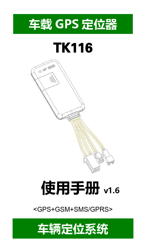
----TK116使用手册v1.6<GPS+GSM+SMS/GPRS>-车辆定位系统--目录一、产品功能、规格 (5)1.1产品功能 (5)1.2产品规格 (6)二、产品结构、配件 (7)2.1产品结构 (7)2.2产品配件 (8)三、安装SIM卡 (9)3.1安装前的准备 (9)3.2SIM卡的安装 (9)3.3取出SIM卡 (10)四、终端安装 (11)4.1安装设备到车辆 (11)4.2终端如何接线 (12)4.3继电器接线 (16)4.4安装麦克风 (16)4.5安装SOS求救按钮 (17)五、开启/关闭终端 (17)5.1开机 (17)5.2状态指示灯 (17)5.3关机 (18)六、查询、监听、切断/恢复油路..186.1短信查询 (18)6.2终端服务平台查询 (18)6.3终端监听 (19)6.4切断/恢复油路 (19)七、终端配置 (20)八、终端报警 (20)8.1振动报警 (20)8.2碰撞/跌落报警 (20)8.3速度报警 (20)8.4位移报警 (20)8.5电子围栏报警 (21)8.6剪线报警 (21)8.7低电报警 (21)8.8SOS报警 (21)九、故障排除 (22)9.1无法连接服务平台 (22)9.2后台显示离线状态 (22)9.3长时间不定位 (23)9.4定位漂移严重 (23)9.5指令接收异常 (23)十、保修细则 (24)10.1特别声明 (24)10.2保修期 (24)10.3售后服务 (24)Warranty Card/保修卡 (25)感谢您选用购买本机器,请您在使用之前认真阅读本说明书,以便得到正确的安装方法及操作指南,以下描述中终端等同于本机器。
产品外观及配色如有改动,请以实物为准,恕不另行通知。
TK116车用定位跟踪产品借助GPS卫星定位系统、GPRS通信和互联网,通过强大的服务平台可以实现对车辆进行实时远程监测和控制作用。
帮助客户实现透明管理、降低成本、保障安全、提高效率的目标。
中文说明书

中文说明书(总91页) -CAL-FENGHAI.-(YICAI)-Company One1-CAL-本页仅作为文档封面,使用请直接删除IP camera tester 网络视频监控测试仪使用手册()感谢您购买工程宝安防监控视频测试仪。
使用前请务必阅读使用说明书,并正确使用。
为了能安全地使用本仪器,请您先仔细阅读使用说明书上的「安全注意事项」。
说明书阅读后请妥善保管,以便随时查阅、参考。
附有的保修凭证或机身的保修封贴,请勿损坏。
使用中遇到问题,或仪器出现损坏时,请与公司技术部联系。
1目录一、安全事项---------------------------------------------------- 错误!未定义书签。
二、IP网络视频监控测试仪简介------------------------------------ 错误!未定义书签。
概述 ---------------------------------------------------- 错误!未定义书签。
产品特点 ------------------------------------------------ 错误!未定义书签。
产品功能 ------------------------------------------------ 错误!未定义书签。
产品配件 ------------------------------------------------ 错误!未定义书签。
仪表各部位名称和功能:----------------------------------- 错误!未定义书签。
三、操作说明---------------------------------------------------- 错误!未定义书签。
电池安装及充电说明--------------------------------------- 错误!未定义书签。
DVR Max 16 产品说明书

MAX16: 16-Ch Slim H.264E DVR with Audio/Video Recording Dual StreamMax16 (480/480FPS)• OS: Embedded Linux® • Microprocessor: Motorola® BlackFin®• Compression Technology: H.264E• System Resource: Pentaplex Function.• Video Inputs: 16 Chs. (16 Chs. Looping)• Display Rate: 1 to 30fps / Ch.• Record Rate: 1 to 30fps / Ch.• Display Resolution: CIF/D1.• Rec. Resolution: [(1st & 9th Ch D1/30fps),(2nd to 8th &10th to 16th CIF/30fps)].• Playback Display: 16 Chs.• Video Outputs: 1 channel TV output BNC 1.0Vp- p, 75Ώ, 1 VGA output, 1 HDMI output, 1 Matrix. (all available thesame time) • Audio Inputs: 4 Chs.• Audio Outputs: 2 Chs. (one bidirectional)• Audio Compression: G.711• Motion Detection: 396 (22*18) zones, 6 Sensitivity levels• Alarm Inputs: 16 Chs.• Alarm Outputs: 5 Chs. Dry Contacts, 1 12V output.• Storage Capability: 4 SATA Ports (8TB) without DVD/RW.• External Storage: eSATA. (5TB) for backup only• Network Connection: RJ45 10M/100M Ethernet.• Dual Stream: flexible for network transmission ,allows gradual network framerates transmission.• Control Ports: 1 RS232, 1 RS485, 2 USB2.• MSS: (mobile surveillance software for smart phone) optional.• Bulit-in DVD/RW (optional).Max16SystemMain Processor High performance embedded microprocessor Motorola® BlackFin®Operating System Embedded Linux®System Resources Pentaplex function: live, recording, playback, backup & remote accessUser Interface GUI, on-screen menu tipsControl Device Front panel, USB mouse, IC Realtime keyboard, IR remote control, network keyboardInput Method Numeral/Character/DenotationSystem Status HDD status, data stream statistics, log record, bios version, on-line user etc.VideoVideo Input 16 channel, BNC, 1.0Vp-p, 75ohm,loopingVideo Output 1 BNC, 1 Vp- p 75Ω, 1 VGA output, 1 HDMI output, 1 Matrix (All Available at the sametime)Video Standards PAL(625Line, 50f/s), NTSC(525Line, 60f/s)Video Compression H.264Format NTSC PAL Video ResolutionD1(4CIF) 704 X 480 704 X 576CIF 352 X 240 352 X 288Video RecordingCIF: PAL 1f/s~25f/s, NTSC 1f/s~30f/s4CIF: PAL 1f/s-25f/s NTSC 1f/s-30f/s[(1st & 9th Ch D1/30fps),(2nd to 8th & 10th to 16th Ch CIF/30fps)]. Or [(1st & 9th ChD1/30fps),(2nd to 8th & 10th to 16th Ch CIF/7.5fps)]Dual encoding streams supportedVideo Display Split Full and multiple screen display, 1 / 4 / 9 / 16Tour Display SupportImage Quality 1~6 level(level 6 is the best)Privacy Masking 4 self-defined four-sided zones for privacy masking for each cameraCamera Lock Camera locked for usersCamera Adjustment Adjust color according to different time periodVideo Information Camera title, time, video loss, camera lock, motion detection, recordingTV Output Adjustment Adjust TV output color & display zoneAudioAudio Input 4/4 channel, BNC, 200-2800mV, 30KΩBidirectional Talk Input 1 channel, BNC, 200-2800mV, 30KΩAudio Output 1 channel, BNC, 200-3000mv, 5KΩAudio Compression G.711Video Detection & AlarmMotion DetectionZones: 396 (22*18) detection zonesSensitivity: 1~6 (level 6 is highest)Trigger recording, PTZ movement, tour, alarm, email, matrix outputVideo Loss Trigger recording, PTZ movement, tour, alarm, email, matrix outputCamera Blank Trigger recording, PTZ movement, tour, alarm, email, matrix output8/16 channel, programmable, ground, manual open/closedAlarm InputTrigger recording, PTZ movement, tour, alarm, email, matrix outputRelay output 3/3 channel, 30VDC, 1A, NO/NC, form-CHard DiskH ard Disk 4 SATA ports, 4 HDDs supported. (Up to 8TB without DVD/RW) or (4 TB with DVD/RW) Space Occupation Audio: 14.4MB/H Video: 56 500MB/HHDD Management Hard disk hibernation technology, HDD faulty alarm & Raid(Redundancy)External Storage 1 eSATA port (For Backup Only)Record, Playback & BackupRecording Mode Manual, continuous, 6 Schedule, video detection (including motion detection, camera blank,video loss), AlarmRecording Priority Manual >Alarm >Video Detection >ContinuousRecording Interval 1 to 120 minutes (default: 60 minutes), Pre-record up to 30 seconds, Post-record up to 5minutesOverwrite Mode SupportSearch Mode Time/Date, Alarm, Motion Detection, Video Loss & exact search (accurate to second) Playback 16 channel playback simultaneously, pause, stop, rewind, fast play, slow play, next file,previous file, next camera, previous camera, full screen, repeat, shuffle, backup selectionDigital Zoom Selected zone can zoom into full screen during playbackBackup Mode Flash disk/ USB HDD/ USB CD/DVD-RW/ Network download / eSATA (Built-in SATAburner Optional)NetworkInterface RJ-45 Port (10/100M)Network Functions TCP/IP, UDP, DHCP, DNS, IP Filter, PPPOE, DDNS, FTP, Email, Alarm ServerRemote operation Monitor, PTZ control, playback, system setting, file download, log informationMSS (Mobile Smart Phones Monitoring) Supported (Optional)Auxiliary InterfaceUSB Interface 2 ports, 1 for mouse control, 1 for backupRS232 IC Realtime keyboard, PC communicationcontrolRS485 PTZ。
H0T Series 音频隧道摄像头用户手册说明书

H0T Series Audio Turret CameraUser ManualUser ManualThank you for purchasing our product. If there are any questions, or requests, do not hesitate to contact the dealer.This manual applies to the models below:Type ModelType I DS-2CE78H0T-IT3FSType II DS-2CE76H0T-ITPFSType III DS-2CE76H0T-ITMFSThis manual may contain several technical mistakes or printing errors, and the content is subject to change without notice. The updates will be added to the new version of this manual. We will readily improve or update the products or procedures described in the manual.0107001090428Regulatory InformationFCC InformationPlease take attention that changes or modification not expressly approved by the party responsible for compliance could void the user’s authority to operate the equipment.FCC compliance: This equipment has been tested and found to comply with the limits for a Class A digital device, pursuant to part 15 of the FCC Rules. These limits are designed to provide reasonable protection against harmful interference when the equipment is operated in a commercial environment. This equipment generates, uses, and can radiate radio frequency energy and, if not installed and used in accordance with the instruction manual, may cause harmful interference to radio communications. Operation of this equipment in a residential area is likely to cause harmful interference in which case the user will be required to correct the interference at his own expense.FCC ConditionsThis device complies with part 15 of the FCC Rules. Operation is subject to the following two conditions:1. This device may not cause harmful interference.2. This device must accept any interference received, including interference that may cause undesired operation.EU Conformity StatementThis product and - if applicable - thesupplied accessories too are marked with"CE" and comply therefore with theapplicable harmonized European standards listed under the Low Voltage Directive2014/35/EU, the EMC Directive 2014/30/EU, the RoHS Directive 2011/65/EU.2012/19/EU (WEEE directive): Productsmarked with this symbol cannot bedisposed of as unsorted municipal waste inthe European Union. For proper recycling,return this product to your local supplierupon the purchase of equivalent new equipment, or dispose of it at designated collection points. For more information see: . 2006/66/EC (battery directive): This product contains abattery that cannot be disposed of asunsorted municipal waste in the EuropeanUnion. See the product documentation forspecific battery information. The battery ismarked with this symbol, which may include lettering to indicate cadmium (Cd), lead (Pb), or mercury (Hg). For proper recycling, return the batteryto your supplier or to a designated collection point. For more information, see: .Industry Canada ICES-003 ComplianceThis device meets the CAN ICES-3 (A)/NMB-3(A) standards requirements.WarningThis is a class A product. In a domestic environment this product may cause radio interference in which case the user may be required to take adequate measures.Safety InstructionThese instructions are intended to ensure that user can use the product correctly to avoid danger or property loss.The precaution measure is divided into “Warnings” and “Cautions”.Warnings: Serious injury or death may occur if any of the warnings are neglected.Cautions: Injury or equipment damage may occur if any of the cautions are neglected. ArrayWarnings●In the use of the device, you must be in strict compliance with the electrical safety regulations of the nation and region.●Input voltage should meet both the SELV (Safety Extra Low Voltage) and the Limited Power Source with 12 VDC according to the IEC60950-1 standard. Refer to technical specifications for detailed information.●Do not connect multiple devices to one power adapter to avoid over-heating or a fire hazard caused by overload.●Make sure that the plug is firmly connected to the power socket.●Make sure that the device is firmly fixed if wall mounting or ceiling mounting is adopted.●If smoke, odor or noise rise from the device, turn off the power at once and unplug the power cord, and then contact the service center.●Never attempt to disassemble the camera by unprofessional personal.Cautions●Do not drop the camera or subject it to physical shock.●Do not touch senor modules with fingers.●Do not place the camera in extremely hot, cold (the operating temperature shall be -40°C to 60°C), dusty or damp locations, and do not expose it to high electromagnetic radiation.●If cleaning is necessary, use clean cloth with a bit of ethanol and wipe it gently.●Do not aim the camera at the sun or extra bright places.●The sensor may be burned out by a laser beam, so when any laser equipment is in using, make sure that the surface of sensor will not be exposed to the laser beam.●Do not expose the device to high electromagnetic radiation or extremely hot, cold, dusty or damp environment.●To avoid heat accumulation, good ventilation isrequired for the operating environment.●Keep the camera away from liquid while in use for non-water-proof device.●While in delivery, the camera shall be packed in its original packing, or packing of the same texture.Mark Description1 Introduction1.1 Product FeaturesThe main features are as follows: ● High performance CMOS sensor● OSD menu with configurable parameters ● Smart IR● Audio over coaxial cable ● Built -in mic● 4 in 1 video output1.2 Overview1.2.1 Overview of Type I CameraEnclosureMain Body Mounting BaseSwitch ButtonPower Cord Video CableFigure 1-1 Overview of Type I CameraNote:Press and hold the switch button for 5 seconds to switch the video output. Four kinds of video outputs are available: TVI, AHD, CVI, and CVBS. 1.2.2 Overview of Type II CameraMounting Base Main Body EnclosureSwitch Button Power Cord Video CableFigure 1-2 Overview of Type II CameraNote:Press and hold the switch button for 5 seconds to switch the video output. Four kinds of video outputs are available: TVI, AHD, CVI, and CVBS. 1.2.3 Overview of Type III CameraMounting Base Clip PlateMain BodySwitch Button Power Cord Video CableEnclosureFigure 1-3 Overview of Type III CameraNote:Press and hold the switch button for 5 seconds to switch the video output. Four kinds of video outputs are available: TVI, AHD, CVI, and CVBS.2InstallationBefore you start●Make sure that the device in the package is in good condition and all the assembly parts are included.●Make sure that all the related equipment is power-off during the installation.●Check the specification of the products for the installation environment.●Check whether the power supply is matched with your power output to avoid the damage.●Make sure the wall is strong enough to withstand three times the weight of the camera, and the mount.●If the wall is cement, insert expansion bolts before installing the camera. If the wall is wooden, useself-tapping screws to secure the camera.●If the product does not function properly, contact your dealer or the nearest service center. Do NOT disassemble the camera for repair or maintenance by yourself.2.1Installation of Type I Camera2.1.1Ceiling/Wall Mounting without Junction Box Before you start:The installation of ceiling mounting and wall mounting are similar. Following takes ceiling mounting as an example.Steps:1.Disassemble the camera by rotating the camera toalign the notch to one of the line, as shown in thefigure below.Figure 2-1Dissemble the Camera2.Pry the mounting base by using a flat object, forexample, a coin.Figure 2-2Pry the Mounting Base3.Drill the screw holes and the cable hole (optional)on the ceiling.4.Attach the mounting base to the ceiling and secureit with supplied screws. For cement ceiling, youneed to install the expansion bolts at first.Expansion BoltsScrewsFigure 2-3Attach the Mounting Base to the Ceiling 5.Route the cables through the cable hole, or the sideopening.6.Install the camera back to the mounting base andsecure it.Figure 2-4Install the Camera Back7.Connect the corresponding power cord, and videocable.8.Power on the camera to check whether the imageon the monitor is gotten from the optimum angle. If not, adjust the camera according to the figure below to get an optimum angle.Pan Position[0° to 360°]Tilt Position[0° to 75°]Rotation Position[0° to 360°]Figure 2-53-Axis Adjustment1).Rotate the enclosure to adjust the pan position[0° to 360°].2).Move the camera body up and down to adjustthe tilt position [0° to 75°].3).Rotate the main body to adjust the rotationposition [0° to 360°].2.1.2Ceiling/Wall Mounting with Junction Box Before you start:You need to purchase a junction box in advance. Steps:1.Drill screw holes and the cable hole according onthe wall.2.Take apart the junction box, and align the screwholes of the mounting base with those on theJunction box’s cover.3.Install the mounting base to the junction box’s coverwith three PM4 screws.Figure 2-6Secure screws on the Junction Box’s Cover 4.Secure the junction box’s body on the wall with fourPA4 × 25 screws.Figure 2-7Secure the Junction Box on the Wall 5.Route the cables through the bottom cable hole, orthe side cable hole of the junction box.bine the junction box cover with its body.Figure 2-8Combine the Junction Box’s Cover back to itsBody7.Repeat the step 6 to 8 of 2.1.1Ceiling/WallMounting without Junction Box to finish theinstallation.2.2Installation of Type II Camera2.2.1Ceiling/Wall Mounting without Junction Box Before you start:The installation of ceiling mounting and wall mounting are similar. Following takes ceiling mounting as an example.1.Pry the mounting base by using a flat object, forexample, a coin.Figure 2-9Pry the Mounting Base2.Drill screw holes and the cable hole (optional) onthe wall.3.Attach the mounting base to the ceiling and secureit with supplied screws. For cement ceiling, youneed to install the expansion bolts at first.Figure 2-10Attach the Mounting Base to the Ceiling4. Route the cables through the cable hole, or the side opening.5. Install the camera back to the mounting base and secure it.Figure 2-11 Install the Camera Back6. Connect the corresponding power cord, and video cable.7. Power on the camera to check whether the image on the monitor is gotten from the optimum angle. If not, adjust the camera according to the figure below to get an optimum angle.Pan Position [0° to 360°]Rotation Position [0° to 360°]Tilt Position [0° to 75°]Figure 2-12 3-Axis Adjustment2.2.2 Ceiling/Wall Mounting with Junction Box Before you start:You need to purchase a junction box in advance. 1. Paste the drill template on the ceiling/wall .2. Drill screw holes and the cable hole according to the drill template.Figure 2-13 Drill Template of the Junction Box 3. Take apart the junction box, and align the screw holes of the mounting base with those on the Junction box’s cover .4. Install the mounting base to the junction box’s cover with screws.Figure 2-14 Install the Mounting Base5.Secure the junction box’s body on the ceiling withfour PA4 × 25 screws and expansion bolts.Figure 2-15Secure the Junction Box on the Ceiling 6.Route the cables through the bottom cable hole, orthe side cable hole of the junction box.bine the junction box cover with its body.Figure 2-16Combine the Junction Box’s Cover back toits Body8.Repeat the step 5 to 7 of 2.2.1 Ceiling/WallMounting without Junction Box to finish theinstallation.2.3Installation of Type III Camera2.3.1Ceiling/Wall Mounting without Junction Box Before you start:The installation of ceiling mounting and wall mounting are similar. Following takes ceiling mounting as an example.Note:For installation with junction box refers to 2.2.2 Ceiling/Wall Mounting with Junction Box.1.Disassemble the turret camera by loosening thescrew.2.Remove the mounting base from the main body.Figure 2-17Remove the Mounting Base3.Drill the screw holes and the cable hole (optional)on the ceiling.4.Secure the mounting base to the ceiling withsupplied screws.Figure 2-18Secure the Mounting Base to the Ceiling 5.Route the cables through the cable hole, or the sideopening.6.Secure the camera on the mounting base.1)Pull out the clip plate, and then to combinethe camera with the mounting base.2)Push the clip plate in, and secure the cameraby tightening the screw.Clip PlateScrewFigure 2-19Secure the Camera7.Connect the corresponding cables, such as powercord, and video cable.8.Power on the camera to check whether the imageon the monitor is gotten from the optimum angle. If not, adjust the camera according to the figure below to get an optimum angle.Pan Position[0° to 360°]Tilt Position[0° to 75°]Rotation Position[0° to 360°]Figure 2-203-Aixs Adjustment3 Menu DescriptionPlease follow the steps below to call the menu. Note:The actual display may vary with your camera model. Steps:1. Connect the camera with the TVI DVR, and the monitor, shown as the figure 3-1.Figure 3-1 Connection2. Power on the camera, TVI DVR, and the monitor to view the image on the monitor.3. Click PTZ Control to enter the PTZ Control interface.4. Call the camera menu by clicking button, or callFigure 3-2 Main Menu Overview5. Click the direction arrow to control the camera.1).Click up/down direction button to select theitem.2).Click Iris + to confirm the selection.3).Click left/right direction button to adjust thevalue of the selected item.3.1VIDEO FORMATYou can set the video format to 5MP@20fps,4MP@30fps, 4MP@25fps, 2MP@30fps, or2MP@25fps.3.2EXPOSUREEXPOSURE MODEYou can set the EXPOSURE MODE to GLOBAL, BLC, HLC, or DWDR.●GLOBALGLOBAL refers to the normal exposure mode which adjusts lighting distribution, variations, andnon-standard processing.●BLC (Backlight Compensation)BLC (Backlight Compensation) compensates light to the object in the front to make it clear, but this may cause the over-exposure of the background where the light is strong.●HLC (Highlight Compensation)HLC stands for highlight compensation. The camera detects the strong spots (the over-exposure portion of image), then reduce the brightness of the strong spots to improve the overall images.●DWDR (Digital Wide Dynamic Range)Digital wide dynamic range gives the camera the ability to view dark areas of the given image as well as extremely lighted portions of the image, or areas of high contrast.AGC (Auto Gain Control)It optimizes the clarity of the image in poor light conditions. The AGC level can be set to HIGH, MEDIUM, or LOW.Note:The noise will be amplified when setting the AGC level.3.3DAY/NIGHTCOLOR, B&W (Black and White), and AUTO are selectable for DAY/NIGHT switch.COLORThe image is colorful in day mode all the time.B&W (Black and White)The image is black and white all the time, and the IR LIGHT turns on in the poor light conditions.You can turn on/off the IR LIGHT and set the value of SMART IR in this menuFigure 3-3DAY/NIGHT●IR LIGHTYou can turn on/off the IR LIGHT to meet the requirements of different circumstances.●SMART IRThe Smart IR function is used to adjust the light to its most suitable intensity, and prevent the image from over exposure.AUTOAutomatically switch Color, or B&W (Black and White) according to actual scene brightness.You can turn on/off the IR LIGHT, and set the value of SMART IR in this menu.Figure 3-4DAY/NIGHT●IR LIGHTYou can turn on/off the IR LIGHT to meet the requirements of different circumstances.●SMART IRThe Smart IR function is used to adjust the light to its most suitable intensity, and prevent the image from over exposure.●D→ N Threshold (Day to Night Threshold)Day to Night Threshold is used to control the sensitivity of switching the day mode to the night mode. You can set the value from 1 to 9. The larger the value is, the more sensitive the camera is.●N→ D Threshold (Night to Day Threshold)Night to Day Threshold is used to control the sensitivity of switching the night mode to the day mode. You can set the value from 1 to 9. The larger the value is, the more sensitive the camera is.3.4VIDEO SETTINGSMove the cursor to VIDEO SETTINGS and click Iris+ to enter the submenu. IMAGE MODE, WHITE BALANCE, BRIGHTNESS, CONTRAST, SHARPNESS, SATURATION, DNR, and MIRROR are adjustable.Figure 3-5VIDEO SETTINGSIMAGE MODEIMAGE MODE is used to adjust the image saturation, and you can set it to STD (Standard) or HIGH-SAT (High Saturation).WHITE BALANCEWhite balance, the white rendition function of the camera, is to adjust the color temperature according to the environment. It can remove unrealistic color casts in the image. You can set WHITE BALANCE mode to AUTO, or MANUAL.●AUTOUnder AUTO mode, white balance is being adjusted automatically according to the color temperature of the scene illumination.●MANUALYou can set the R-GAIN/B-GAIN value to adjust the shades of red/blue color of the image.Figure 3-6MWB MODE BRIGHTNESSBrightness refers to the brightness of the image. You can set the brightness value from 1 to 9 to darken or brighten the image. The greater the value is, the brighter the image is.CONTRASTThis feature enhances the difference in color and light between parts of an image.SHARPNESSSharpness determines the amount of detail an imaging system can reproduce.SATURATIONSaturation is the proportion of pure chromatic color in the total color sensation. Adjust this feature to change the saturation of the color.DNRDNR refers to digital noise reduction.This function reduces noise in video stream.MIRROROFF, H, V, and HV are selectable for mirror.OFF: The mirror function is disabled.H: The image flips 180° horizontally.V: The image flips 180° vertically.HV: The image flips 180° both horizontally and vertically.3.5AUDIO SETTINGSUnder the AUTO SETTINGS sub-menu, you can set the mode to ON or OFF. Set the LEVEL to a high value to raise the volume.Figure 3-7AUTO SETTINGS3.6FACTORY DEFAULTReset all the settings to the factory default.3.7EXITMove the cursor to EXIT and click Iris+ to exit the menu.3.8SAVE & EXITMove the cursor to SAVE & EXIT and click Iris+ to save the settings, and exit the menu.UD14643B。
System Sensor B116LP 插入式检测器底座说明书
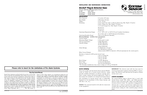
Operating Humidity Range:
10% to 93% Relative Humidity
Electrical Ratings – includes base and detector
System Voltage:
Guide for Proper Use of System Smoke Detectors, which ments. The detector used with this base should be cleaned
provides detailed information on detector spacing, place- at least once a year.
4-inch octagon box. Min. Depth–1.5 inches
3-1/2 inch-octagon box. Min. Depth–1.5 inches
50 mm box
60 mm box
70 mm box
Operating Temperature Range: 0° to +49°C (32° to 120°F) US and Canadian Installations
Specifications
Base Diameter:
6.2 inches (157 mm)
Base Height:
0.95 inches (24 mm)
Weight:
0.3 lb. (130 g)
Mounting:
4-inch square box with or without plaster ring. Min. Depth–1.5 inches
催化燃烧式气体传感器(型号:MC116)使用说明书

催化燃烧式气体传感器(型号:MC116)使用说明书版本号:1.3实施日期:2014-05-01郑州炜盛电子科技有限公司Zhengzhou Winsen Electronic Technology Co., Ltd声明本说明书版权属郑州炜盛电子科技有限公司(以下称本公司)所有,未经书面许可,本说明书任何部分不得复制、翻译、存储于数据库或检索系统内,也不可以电子、翻拍、录音等任何手段进行传播。
感谢您使用本公司的系列产品。
为使您更好地使用本公司产品,减少因使用不当造成的产品故障,使用前请务必仔细阅读本说明书并按照所建议的使用方法进行使用。
如果您没有依照本说明书使用或擅自去除、拆解、更换传感器内部组件,本公司不承担由此造成的任何损失。
您所购买产品的颜色、款式及尺寸以实物为准。
本公司秉承科技进步的理念,不断致力于产品改进和技术创新。
因此,本公司保留任何产品改进而不预先通知的权力。
使用本说明书时,请确认其属于有效版本。
同时,本公司鼓励使用者根据其使用情况,探讨本产品更优化的使用方法。
请妥善保管本说明书,以便在您日后需要时能及时查阅并获得帮助。
郑州炜盛电子科技有限公司MC116催化燃烧式气体传感器产品描述MC116型催化燃烧式气体传感器根据催化燃烧效应的原理工作,由检测元件和补偿元件配对组成电桥的一个臂,遇可燃性气体时检测元件电阻升高,桥路输出电压变化,该电压变化量随气体浓度增大而成正比例增大,补偿元件起参比及温湿度补偿作用。
传感器特点桥路输出电压呈线性、响应速度快、良好的重复性和选择性、工作稳定可靠、抗硫化氢和有机硅干扰性能好。
主要应用工业现场的天然气、液化气、煤气、烷类等可燃性气体的浓度检测,可燃性气体泄漏报警器,可燃性气体探测器,气体浓度计。
技术指标电桥输出图1:传感器外形结构图灵敏度、响应恢复特性输出信号随环境温度的变化输出信号随环境湿度的变化输出信号随工作电压的变化长期稳定性在空气中每年漂移量的绝对值小于2mV,在1%甲烷中每年漂移量的绝对值小于2mV。
FAW A11 003系列-高配版-安装说明书

●线束示意图GNDB+ACCCAN-H(蓝色)CAN-L安装导线车辆侧导线GNDGND接线夹安装注意事项:(A)将车辆侧导线卡入线夹的槽内,将系统线束对应线头装入 线夹,使用尖嘴钳将线夹金属卡扣按压平整,扣回线夹盖。
(B)请在接线夹上裹上绝缘胶带。
贴紧③将DVR尾盖前方扣进DVR 主体对应卡扣位置。
④向上扣紧DVR尾盖。
①将DVR主体穿过后视镜,贴住3M胶底座。
扣住尾部卡扣位置。
③将DVR主体向上扣紧卡扣。
④确保安装牢固。
确保安装牢固。
②将DVR主体往后扣紧卡扣,确保安装牢固。
功能检验1.记录仪上电后,WiFi已自动开启,先将记录仪WiFi与手机连 接,再打开众智途APP(进入APP后输入密码为修改WiFi进入密 码,请谨慎操作),查看视频。
2.正常录像时蓝灯慢闪,系统故障时黄灯常亮(无卡、TF卡错误、 摄像头故障)或黄灯快闪(Bus off、电池电压过高/低、CAN 通信失联)3.启动后,关闭电源记录仪会延时1分钟关闭。
4.请参照使用说明书对各按键进行操作使用。
5.ETC的激活步骤请查阅使用说明书。
(若没有请忽略)重新装回拆卸下来的零件的过程请遵循车辆装配要领说明书。
安装后的确认1.检查连线,零部件的安装是否有异常。
2.检查是否有过分用力按压,拉伸车辆线束及DVR线束的状况。
3.避免忘记安装卡夹,紧固零部件,需进行再一次确认。
七、安装完成后的点检八、车辆零部件恢复③将DVR尾盖前方扣进DVR 主体对应卡扣位置。
④向上扣紧DVR尾盖。
便携式互感器测试仪说明书

便携式互感器测试仪说明书由于输入输出端子、测试柱等均有可能带电压,在插拔测试线、电源插座时,会产生电火花,小心电击,避免触电危险,注意人身安全!安全要求请阅读下列安全注意事项,以免人身伤害,为了避免可能发生的危险,只可在规定的范围内使用。
只有合格的技术人员才可执行维修。
—防止火灾或人身伤害使用适当的电源线。
只可使用专用并且符合规格的电源线。
正确地连接和断开。
当测试导线与带电端子连接时,请勿随意连接或断开测试导线。
注意所有终端的额定值。
为了防止火灾或电击危险,请注意所有额定值和标记。
在进行连接之前,请阅读使用说明书,以便进一步了解有关额定值的信息。
使用适当的保险丝。
只可使用符合规定类型和额定值的保险丝。
避免接触裸露电路和带电金属。
有电时,请勿触摸裸露的接点和部位。
请勿在潮湿环境下操作。
请勿在易爆环境中操作。
-安全术语警告:警告字句指出可能造成人身伤亡的状况或做法。
目录一、概述 (5)二、主要技术指标 (5)三、使用环境条件 (6)四、测量原理 (6)五、使用方法1、面板配置 (7)2、操作键盘 (7)3、开机 (8)4、仪器复位 (8)5、误差测试 (8)6、电网频率测试 (14)一、概述HGQY-H便携式低校高式电压互感器测试仪是最适合于在现场对电压互感器进行误差测试的全自动智能仪器。
用户不再需要配置笨重的升压器,标准电压互感器,负载箱及调压器(或自动检测台),单台仪器就能对10kV、10kV/3、35kV、35kV/3、110kV/3、220kV/3的电压互感器进行快速测量。
全过程(包括额定、下限的所有测量点)的测试时间不超过1分钟(不含接线时间),其准确度达到0.05级。
本仪器采用320×240点阵的大屏幕液晶显示器,各点的误差可以在同一屏上显示,所有操作均可点击屏幕菜单轻松完成。
本仪器可以存贮200组数据,备有专用接口与PC机通讯。
本仪器约重15kg。
二、主要技术指标●测试范围:10kV、10kV/3、35kV、35kV/3、110kV/3、220kV/3●二次负荷:2.5VA~600VA cosФ=0.8●测量精度:0.05级●测频率:准确度为0.01Hz●仪器设有实时时钟,可实时记录测试时间。
- 1、下载文档前请自行甄别文档内容的完整性,平台不提供额外的编辑、内容补充、找答案等附加服务。
- 2、"仅部分预览"的文档,不可在线预览部分如存在完整性等问题,可反馈申请退款(可完整预览的文档不适用该条件!)。
- 3、如文档侵犯您的权益,请联系客服反馈,我们会尽快为您处理(人工客服工作时间:9:00-18:30)。
数码录音笔说明书DVR-116功能特点z一键录音z三种录音模式LP为长时间录音:ACT格式SP为优质声控录音:WAV格式HP为高保真录音:MP3格式z录音监听、助听功能z USB端口即插即用,无须USB连接线 z电话录音与外接麦克风录音功能z录音自动分段z录音时间设置功能z MP3播放功能z低电提示功能z内置扬声器播放z U盘功能z A-B复读功能z内置锂电注意事项●长时间不使用机器时,将电源开关拨至OFF位置。
●使用过程中,电量显示不足时,请及时充电。
●使用前请详细阅读说明书,注意防潮防高温,勿靠近火源。
●避免摔落或强烈碰撞本机,请勿过分用力按压液晶显示屏,否则可能导致液晶屏损坏或显示异常。
●本机出现故障,请与本公司或经销商联系,切勿自行拆卸更换内部零件。
●请经常对录音文件进行备份,因维修或其它原因造成信息丢失,本公司概不负责。
●未经他人允许的录音行为所引起的纠纷,与本产品无关,本公司概不负责。
●本公司保留改进产品的权利,规格及设计如有变动,恕不另行通知。
目录外观图及各部分名称 ┄┄┄┄┄┄┄┄┄┄┄┄┄┄ 1功能操作 ┄┄┄┄┄┄┄┄┄┄┄┄┄┄┄┄┄┄┄ 2开机/关机 ┄┄┄┄┄┄┄┄┄┄┄┄┄┄┄┄┄┄┄ 2录音/停止 ┄┄┄┄┄┄┄┄┄┄┄┄┄┄┄┄┄--- 3录音播放 ┄┄┄┄┄┄┄┄┄┄┄┄┄┄┄┄┄┄┄ 6录音时间设置 ┄┄┄┄┄┄┄┄┄┄┄┄┄┄┄┄┄ 7MP3音乐 ┄┄┄┄┄┄┄┄┄┄┄┄┄┄┄┄┄┄┄- 8A-B复读 ┄┄┄┄┄┄┄┄┄┄┄┄┄┄┄┄┄┄┄- 9删除文件 ┄┄┄┄┄┄┄┄┄┄┄┄┄┄┄┄┄┄┄ 10USB电脑连接 ┄┄┄┄┄┄┄┄┄┄┄┄┄┄┄┄┄- 10充电 ┄┄┄┄┄┄┄┄┄┄┄┄┄┄┄┄┄┄┄┄┄ 11安装应用程序 ┄┄┄┄┄┄┄┄┄┄┄┄┄┄┄┄┄ 12 ACT格式转换┄┄┄┄┄┄┄┄┄┄┄┄┄┄┄┄┄┄12疑难解答 ┄┄┄┄┄┄┄┄┄┄┄┄┄┄┄┄┄┄┄14规格参数 ┄┄┄┄┄┄┄┄┄┄┄┄┄┄┄┄┄┄┄ 15外观图及各部分名称(1)播放/开关机/暂停键()(2)菜单键/删除键(M )(3)快退键() (4)快进键() (5)录音键(REC) (6)音量加键(+)(7)音量减键(-) (8)电源开关 (ON/OFF)(9)耳机孔() (10)信号输入孔()(11)显示屏 (12)USB(13)指示灯 (14)内置麦克风功能操作开机/关机●开机:在断电状态下将ON/OFF电源开关键拨至“ON”位置,等待约3秒显示屏点亮,录音笔开机。
在关机状态下,长按键录音笔开机。
如下图所示:若录音笔里已有SP或LP录音文件,则进入录音放音待机状态。
如下图所示:若录音笔里没有SP或LP录音文件,录音笔自动退出到录音放音模式。
如下图所示:z关机:待机状态下,长按键,显示屏显示“OFF”后熄灭,录音笔关机。
如下图所示:● 低电提示:录音笔电量不足时会出现低电量图标,此时如果您正在录音没有留意,录音笔会自动保存录音文件,等待30秒后自动关机。
请用户及时充电。
录音/停止z一般录音操作:在待机状态下,按M键进入主菜单,再按键选择所需录音模式,按REC键开始录音,指示灯闪动,再按REC键,指示灯熄灭,停止并保存录音。
各种录音模式如下图:LP:长时间录音,ACT格式SP:优质声控录音,WAV格式HP:高保真录音,MP3格式SP录音是默认的录音模式,声控级别可以根据声音来源大小进行调节(声控最小级别是0,最大级别是4,默认级别为0 ),具体操作如下:在SP声控录音时按REC键让录音处于停止状态,再按 键根据录入声音大小选择适当的声控级别,让声控有效起控,然后再按REC键开始下一段录音。
当没有声音录入时图标闪烁,时间停止跳动,录音笔处于录音暂停状态。
当有声音录入时图标熄灭,录音笔恢复到正常录音状态。
显示如下:(录音暂停) (正常录音)再按REC键,停止并保存录音,指示灯熄灭,显示如下:注意:当显示屏上显示“FUL”字符时,说明磁盘空间已满或在低电的情况下工作,则必须删除一些内容,确保有足够空间才能录音或存贮其它信息,如果是低电则需充电后才能正常工作。
录音笔在录音和放音过程中切勿关闭电源,否则会造成信息丢失或死机现象。
由于误操作引起的死机现象,需在电脑上格式化(格式化时文件系统选FAT)后才能正常使用。
误操作引起的信息丢失本公司不负责任。
z一键录音操作:在任何待机状态下按REC键,指示灯闪动,开始录音,再按REC键,指示灯灭,停止并保存录音。
操作快捷方便。
z电话录音操作连接设备:把电话线和录音笔附带的电话连接线接入电话适配器,然后将音频线一端连接电话适配器,另一端插入孔(如上图示)。
录音操作:请参考录音操作和一键录音操作。
● 外接麦克风录音连接设备:将外接麦克风的一端插入孔。
录音操作:请参考录音操作和一键录音操作。
● 录音监听、助听:监听功能:在录音时带上耳塞可以监听到录音的内容以及录音笔在不同情况下的录音效果。
助听功能:对于听力欠佳者可以调节监听音量以达到助听的效果。
监听音量大小调节:在录音时按REC键让录音处于停止状态,再按+键或-键根据需要选择音量大小,然后再按REC键开始录音。
最小音量为0,最大音量为31。
提示:在HP录音模式下无此功能。
z自动分段录音笔连续录音满4小时会自动保存并开始下一段 录音。
◆ 录音播放z播放/停止:在主菜单下按 键选择录音放音模式,再按M键进入录音放音待机状态,按 键开始依次播放录音文件,再按 键暂停播放。
在SP或LP录音停止状态下,按 键开始播放当前录音文件并依次播放其它录音文件,再按 键暂停播放。
HP录音需在MP3音乐模式下播放(具体操作参考MP3音乐播放)。
z音量选择:按+键或-键对音量大小进行调节。
z选曲、快进、快退:在播放状态下短按 键选择上曲或下曲,长按键为快进或快退。
◆ 录音时间设置z时间设置:在主菜单下按 键选择时间设置模式。
如下图:按M键进入,再按 键依次选择需要调节的部分,选定的部分会不断闪动,按+键或-键调节具体的时间。
如下图:设置完成后本机已自动确认。
待机约10秒或按M键回到主菜单。
● 时间查看将需要查看录音时间的录音文件上传到电脑,点击鼠标右键打开录音文件属性,在[常规]项里可以查看到录音时间,如下图:注意:设置好当前时间后,若关掉电源开关,时间将会恢复为默认设置。
本机不具备时钟功能,所记录和走的时间与日常时间有差别,当您需要使用时间功能时,请重新设定时间。
◆ MP3音乐z MP3音乐模式:在主菜单下按 键选择音乐模式(如图1),再按M键进入音乐放音待机状态(如图2),如果没有音乐文件或HP录音文件则退出到主菜单。
(1) (2) z播放/暂停:在音乐放音停止状态下,按 键开始播放,再按键暂停播放。
z音量选择:按+键或-键对音量大小进行调节。
z选曲、快进、快退:在播放状态下短按 键选择上曲或下曲,长按键为快进或快退。
◆ A—B复读● 确定A-B点:在播放状态下,按REC键确定复读的起点A,再按REC 键确定复读的终点B,录音笔开始从起点A到终点B的复读。
z取消复读:MP3复读状态下,复读3遍后自动取消,也可按REC 键或M键手动取消。
录音复读状态下无限制次数进行复读,按REC键或M 键或 键取消。
删除文件在放音停止状态下,选择需要删除的文件,长按M键约3秒后出现如下界面:再按M键确认删除,删除中出现如下界面:提示:进入删除状态后,3秒内不对机器进行任 何操作,录音笔会自动退出删除状态。
注意:在进行删除和格式化操作前,重要文件请在电脑上备份!◆ USB电脑连接将录音笔USB端口插入电脑USB端口,即与电脑连接,出现如下界面:本机具有U盘功能,连接上电脑后就可以在电脑和录音笔之间相互传送资料。
本机支持Windows98/Me/2000/XP/Vista系统,在Windows98系统下需要安装USB驱动。
本机支持USB供电,在USB模式下按M键退出到主菜单或录音放音待机状态,然后再进行正常操作。
关断电源后在USB供电状态时,放音只能使用耳机收听。
注意:在和电脑数据交换过程中不要拔下录音笔,否则会造成录音笔信息丢失或死机现象,需在电脑上进行FAT格式化后才能正常使用。
◆充电将随机所配的充电器,一端插入家用交流电插座(110V-250V),此时充电器黄灯亮,另一端连入录音笔的USB端口,充电时录音笔指示灯和充电器红灯亮,充满电时录音笔指示灯灭,显示屏上同时显示“FUL”字符(如下图)。
待电池电量完全饱和后充电器红灯熄灭黄灯亮,新机在第一次充电前必须先把电放完,然后充电6小时以上。
可延长电池使用寿命。
连接电脑充电时,录音笔指示灯亮,充满电后指示灯灭,显示屏上同时显示“FUL”字符。
◆ 安装应用程序将随机附带的安装光盘放入电脑的光驱内(或手动运行光盘中的“setup.exe”),进入安装界面,点击[下一步]按扭,选择安装路径后点击[下一步]按扭。
点击[下一步]按[开始]安装程序。
安装成功后在电脑的[开始]→[程序]中会安装[MP3 Player Utilities]菜单,有3个子目录,其中[MP3 Player Disk Tool]为磁盘加密工具,[MP3 Player Updade Tool]为升级工具,[Sound Convert Tool]为录音转换工具。
◆ACT格式转换本录音笔录制的ACT格式文件可以转换为WAV格式。
● 在电脑上运行[Sound Converter Tool]程序,点击[打开]按钮。
● 选择要转换的ACT文件。
● 点击[转换]按钮,开始转换为WAV文件。
● 除了可以将ACT格式转换为WAV格式功能外,本软件还可以播放WAV和MP3格式文件。
注意:转换后的WAV文件会替换原录音笔内同名的WAV 文件,请在电脑上备份同名的WAV文件或重命名。
疑难问题●不能开机请确定电源开关是否在“ON”位置或者电池电量是否充足。
●播放文件时没有声音请确保耳机的连接没有问题,音量是否关闭或是您播放的文件损坏本身就没有声音。
●有时不能录音这是因为频繁进行某些操作或误操作导致机内程序紊乱,只要连接电脑对本机进行格式化即可(文件系统选FAT),格式化前请保存机内有用文件。
●出现死机,操作无响应连接电脑对本机进行格式化(文件系统选FAT),格式化前请保存机内有用文件。
●不能与电脑连接检查本机是否和电脑连接好,驱动程序是否安装妥当。
规格参数尺寸:96mm*30mm*13mm 重量:34g供电:锂电 3.7V 180mAh 内存容量:128MB~2GB录音位率 LP 8Kbps/SP 32Kbps/HP 128Kbps128MB:LP 约35小时/SP 约8小时/ HP 约2小时256MB:LP 约70小时/SP 约17小时/HP 约4小时 512MB:LP 约140小时/SP 约35小时/HP 约9小时 1GB: LP 约280小时/SP 约70小时/HP 约17小时 录音 时间2GB:LP 约560小时/SP 约140小时/HP 约34小时频率响应 20Hz~20KHz MP3信噪比 80db最大音频输出功率 10mw(L)+10mw(R) 支持系统Windows98/Me/2000/XP/Vista 音乐格式 MP3 WMA 录音格式 MP3 WAV ACT。