英飞拓V2020矩阵(infonova V2020)Datasheet
英飞拓光端机
独立式
插卡式
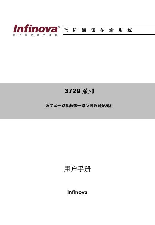
3729 系列光端机兼容 9/125 微米单模光纤
接在摄像机端的发射机 3729TA 同接在监视器端的接收机 3729RA 配套使用
附件(可选) 3910-000 3932 3951 3952 3954
19 英寸 1U 散热风扇 一路数据加一路视频防雷保护卡 光纤传输中继器 开关信号采集器 控制码分配器
独立式光端机电源配置 将 3729 插卡式光端机安装到 1 个单槽机箱 3910-1S 时,则变成独立式光端机。
此时,该光端机可以由 1 个 12VDC@1A 插入式直流电源(3921-12D-1,110V; 3921-12D-2,230V)供电。将导线插入到光端机电源连接座内,用螺丝刀将导线锁紧, 见下图。
注意事项
本产品应由专业的技术人员进行安装。非专业人员请勿擅自安装操作。安装操 作请联系专业人员。
在该产品的安装过程中,如果你需要相关信息或服务,请联系当地供应商,或 者请拨打 INFINOVA 客户服务专线:1-732-355-9100,51 Stouts Lane, Monmouth Junction, NJ 08852 U.S.A. 注意,在返送任何产品进行维修前,请务必索取返修授权 号码和装运说明书。
图 4. 菊花链接 注意:
请在最后一个接收机处接上 120 欧姆终端电阻来抑制信号反射。 8
浪涌保护
浪涌保护电路用于保护 Infinova 光端机免受瞬时浪涌和过载电压的破坏。交流 电源或闪电产生的感应电流都可能引发电压过载,并传导到数据线,进而损坏光端 机内部芯片,造成光端机工作不正常甚至失效。良好的接地装置能保证光端机内部 过压保护电路功能正常实现。为增强保护效果,我们建议用户采用 3932 来保护光端 机设备不受浪涌和过载电压的危害。下图为采用了 3932 防雷保护卡后,光端机的一 个工作示意图:
英飞拓矩阵V2020中文说明书
标志提醒用户严格按照本手册的说明和指示进行安装和操作。
警告:为避免火灾及电击的危险,请勿将本产品放置于雨淋或潮湿的地方!
目录
第一章 一般描述 ........................................................................... 1 1.1 特性 ..................................................................................... 1 1.2 描述 ..................................................................................... 1 1.3 关键术语 ............................................................................. 2 1.4 型号 ..................................................................................... 3 1.5 系统附件 ............................................................................. 4
请仔细阅读本手册,并妥善保存好本手册,以便将来查阅。
安全建议与警告
所有电子设备应避免受潮,远离火源或强磁场。 擦拭设备表面时,请使用干燥、柔软的抹布。 请保持设备周围良好的通风环境。 设备长时间不用时,请断开电源。 请使用厂家建议的原配件。 电源及电线应安装在远离地面和入口处的地方。 设备的维护需由专业人员进行。 建议妥善保管包装箱,方便设备的转移或搬运。
8200系列QAM调制器-用户手册课件
InfoLink DTX8200系列QAM调制器用户指南目录目录1 概述................................................................................................................................................ 1-11.1 简介............................................................................................................................................................... 1-21.2 特性............................................................................................................................................................... 1-31.3 工作原理....................................................................................................................................................... 1-42 设备描述........................................................................................................................................ 2-12.1 设备描述....................................................................................................................................................... 2-22.1.1 设备外观 ............................................................................................................................................. 2-22.1.2 前面板 ................................................................................................................................................. 2-22.1.3 功能键 ................................................................................................................................................. 2-22.1.4 后面板 ................................................................................................................................................. 2-32.2 接口描述....................................................................................................................................................... 2-42.3 设备操作菜单............................................................................................................................................... 2-53 安装指南........................................................................................................................................ 3-13.1 安装流程....................................................................................................................................................... 3-23.2 安装机箱....................................................................................................................................................... 3-23.3 连接线缆....................................................................................................................................................... 3-33.3.1 安装说明 ............................................................................................................................................. 3-33.3.2 连接地线 ............................................................................................................................................. 3-43.3.3 连接DS3输入和输出线缆................................................................................................................. 3-43.3.4 连接ASI输入和输出线缆 ................................................................................................................. 3-53.3.5 连接SPI输入线缆.............................................................................................................................. 3-63.3.6 连接IF中频输入/输出线缆 ............................................................................................................... 3-73.3.7 连接RF射频输出线缆....................................................................................................................... 3-83.3.8 连接10/100M网口 ............................................................................................................................. 3-93.3.9 连接电源线........................................................................................................................................ 3-103.4 启动设备..................................................................................................................................................... 3-114 配置设备参数................................................................................................................................ 4-14.1 配置概述....................................................................................................................................................... 4-24.2 选择输入接口............................................................................................................................................... 4-3目录InfoLink DTX8200系列QAM调制器用户指南4.3 设置DS3模式.............................................................................................................................................. 4-44.3.1 选择模式 ............................................................................................................................................. 4-44.3.2 设置主/备模式号 ................................................................................................................................ 4-54.3.3 搜索模式号.......................................................................................................................................... 4-6 4.4 输出设置....................................................................................................................................................... 4-64.4.1 设置输出频率...................................................................................................................................... 4-64.4.2 设置输出频道...................................................................................................................................... 4-74.4.3 设置QAM调制数 .............................................................................................................................. 4-84.4.4 设置符号率.......................................................................................................................................... 4-94.4.5 设置输出码率...................................................................................................................................... 4-94.4.6 设置射频控制.................................................................................................................................... 4-104.4.7 设置输出增益.................................................................................................................................... 4-114.4.8 设置频谱翻转.................................................................................................................................... 4-11 4.5 码流处理..................................................................................................................................................... 4-124.5.1 设置PID过滤 ................................................................................................................................... 4-124.5.2 设置PID映射 ................................................................................................................................... 4-134.5.3 设置PID插入 ................................................................................................................................... 4-155 配置网络参数................................................................................................................................ 5-15.1 组网简介....................................................................................................................................................... 5-25.2 设置网管IP地址 ......................................................................................................................................... 5-25.3 设置以太网口参数....................................................................................................................................... 5-35.3.1 设置IP地址 ........................................................................................................................................ 5-35.3.2 设置子网掩码...................................................................................................................................... 5-35.3.3 设置网关地址...................................................................................................................................... 5-45.3.4 设置网口模式...................................................................................................................................... 5-55.4 配置TS网口参数 ........................................................................................................................................ 5-55.4.1 打开网口 ............................................................................................................................................. 5-55.4.2 设置IP地址 ........................................................................................................................................ 5-65.4.3 设置子网掩码...................................................................................................................................... 5-65.4.4 设置网管PID ...................................................................................................................................... 5-75.5 配置透明传输网口参数............................................................................................................................... 5-75.5.1 透明传输示例...................................................................................................................................... 5-75.5.2 打开网口 ............................................................................................................................................. 5-85.5.3 设置IP地址 ........................................................................................................................................ 5-85.5.4 设置子网掩码...................................................................................................................................... 5-95.5.5 设置网关地址...................................................................................................................................... 5-95.5.6 设置网元IP ......................................................................................................................................... 5-95.5.7 设置源地址........................................................................................................................................ 5-105.5.8 设置目标地址.................................................................................................................................... 5-11InfoLink DTX8200系列QAM调制器用户指南目录6 典型业务配置................................................................................................................................ 6-16.1 配置复用....................................................................................................................................................... 6-26.2 配置调制....................................................................................................................................................... 6-57 升级指南........................................................................................................................................ 7-17.1 升级准备....................................................................................................................................................... 7-27.2 升级执行....................................................................................................................................................... 7-27.2.1 通过网管系统升级软件...................................................................................................................... 7-37.2.2 通过FTP服务器升级......................................................................................................................... 7-48 例行维护........................................................................................................................................ 8-18.1 设备例行维护项目....................................................................................................................................... 8-28.2 日维护项目................................................................................................................................................... 8-28.3 月维护项目................................................................................................................................................... 8-48.4 年维护项目................................................................................................................................................... 8-68.5 维护表........................................................................................................................................................... 8-78.5.1 日维护表 ............................................................................................................................................. 8-78.5.2 月维护表 ............................................................................................................................................. 8-88.5.3 年维护表 ............................................................................................................................................. 8-99 告警处理........................................................................................................................................ 9-19.1 告警信息处理............................................................................................................................................... 9-29.1.1 查看告警信息...................................................................................................................................... 9-29.1.2 保存告警信息...................................................................................................................................... 9-29.1.3 删除告警信息...................................................................................................................................... 9-29.2 常见告警及处理建议................................................................................................................................... 9-39.2.1 码流类告警.......................................................................................................................................... 9-39.2.2 升级类告警.......................................................................................................................................... 9-49.2.3 其它 ..................................................................................................................................................... 9-410 故障处理.................................................................................................................................... 10-110.1 输入输出故障处理................................................................................................................................... 10-210.1.1 射频信号无输出.............................................................................................................................. 10-210.1.2 射频信号输出偏低.......................................................................................................................... 10-210.1.3 设备输入码流中断.......................................................................................................................... 10-210.2 接收与显示节目故障处理....................................................................................................................... 10-310.2.1 STB不能正常解码节目.................................................................................................................. 10-310.2.2 混频后STB搜索不到节目............................................................................................................. 10-310.2.3 无电视信号...................................................................................................................................... 10-410.2.4 过滤后节目还存在.......................................................................................................................... 10-410.2.5 插入PSI/SI信息导致STB工作异常 ............................................................................................ 10-410.2.6 映射后的节目未能正常播放.......................................................................................................... 10-5目录InfoLink DTX8200系列QAM调制器用户指南10.2.7 图像显示马赛克或定帧.................................................................................................................. 10-5 10.3 网管管理设备故障处理........................................................................................................................... 10-610.3.1 网管不能提取PSI/SI信息 ............................................................................................................. 10-610.3.2 网管不能控制添加的设备.............................................................................................................. 10-610.3.3 网管软件未能成功提取PSI/SI表信息.......................................................................................... 10-711 FAQ ........................................................................................................................................... 11-111.1 名词解释FAQ .......................................................................................................................................... 11-211.2 操作应用FAQ .......................................................................................................................................... 11-3InfoLink DTX8200系列QAM调制器用户指南插图目录插图目录图1-1 DTX8200在数字电视前端的应用......................................................................................................... 1-2图1-2 DTX8200总体结构示意图..................................................................................................................... 1-4图2-1 DTX8200外观示意图............................................................................................................................. 2-2图2-2 DTX8200前面板示意图......................................................................................................................... 2-2图2-3 DTX8208后面板 .................................................................................................................................... 2-3图2-4 DTX8209后面板 .................................................................................................................................... 2-3图2-5 DTX8210后面板 .................................................................................................................................... 2-3图2-6 DTX8211与DTX8211E后面板............................................................................................................. 2-4图2-7 DTX8200接口图 .................................................................................................................................... 2-4图2-8 信息查询项 ............................................................................................................................................. 2-6图2-9 码流处理项 ............................................................................................................................................. 2-6图2-10 输出设置项 ........................................................................................................................................... 2-6图2-11 输入设置项............................................................................................................................................ 2-7图2-12 网络设置 ............................................................................................................................................... 2-7图2-13 系统设置 ............................................................................................................................................... 2-8图3-1 DTX8200安装流程................................................................................................................................. 3-2图3-2 DTX8200的固定 .................................................................................................................................... 3-2图3-3 连接地线 ................................................................................................................................................. 3-4图3-4 75Ω同轴线缆.......................................................................................................................................... 3-4图3-5 DS3输入、输出连接示意图.................................................................................................................. 3-5图3-6 ASI输入、输出连接示意图................................................................................................................... 3-6图3-7 SPI线缆................................................................................................................................................... 3-7图3-8 SPI线缆连接示意图............................................................................................................................... 3-7图3-9 IF输入、IF输出自环连接示意图......................................................................................................... 3-8图3-10 RF射频输出连接示意图...................................................................................................................... 3-9插图目录InfoLink DTX8200系列QAM调制器用户指南图3-11 10/100M网线 ........................................................................................................................................ 3-9图3-12 连接10/100M网口示意图 ................................................................................................................. 3-10图3-13 连接电源和地线.................................................................................................................................. 3-10图3-14 DTX8200启动显示............................................................................................................................. 3-11图4-1 设置过滤参数 ....................................................................................................................................... 4-13图4-2 设置映射参数 ....................................................................................................................................... 4-15图5-1 设置网口IP地址 .................................................................................................................................... 5-3图5-2 设置网口子网掩码.................................................................................................................................. 5-4图5-3 设置网关地址 ......................................................................................................................................... 5-4图5-4 设置网口模式 ......................................................................................................................................... 5-5图5-5 打开TS网口........................................................................................................................................... 5-6图5-6 设置TS网口IP地址.............................................................................................................................. 5-6图5-7 设置TS网口子网掩码 ........................................................................................................................... 5-6图5-8 设置网管PID .......................................................................................................................................... 5-7图5-9 透明传输示例 ......................................................................................................................................... 5-8图5-10 打开透明传输网口................................................................................................................................ 5-8图5-11 设置透明传输网口IP地址 .................................................................................................................. 5-9图5-12 设置透明传输网口子网掩码................................................................................................................ 5-9图5-13 设置透明传输网口网关地址................................................................................................................ 5-9图5-14 设置透明传输网元IP ......................................................................................................................... 5-10图5-15 设置透明传输网口源地址.................................................................................................................. 5-10图5-16 设置透明传输网口目标地址.............................................................................................................. 5-11图6-1 配置组网图 ............................................................................................................................................. 6-2图6-2 基本配置 ................................................................................................................................................. 6-3图6-3 提取表信息 ............................................................................................................................................. 6-4图6-4 复用接口配置 ......................................................................................................................................... 6-5图6-5 配置组网图 ............................................................................................................................................. 6-6图7-1 启动FTP服务器软件............................................................................................................................. 7-2图7-2 升级软件界面 ......................................................................................................................................... 7-3图7-3 选择升级软件 ......................................................................................................................................... 7-4图7-4 设置升级服务器IP地址 ........................................................................................................................ 7-4图7-5 启动程序升级 ......................................................................................................................................... 7-5InfoLink DTX8200系列QAM调制器用户指南表格目录表格目录表2-1 功能及方向键说明.................................................................................................................................. 2-2表2-2 设备接口描述 ......................................................................................................................................... 2-5表3-1 DTX8200安装可选项............................................................................................................................. 3-3表4-1 配置顺序 ................................................................................................................................................. 4-2表4-2 输入接口可选项...................................................................................................................................... 4-3表4-3 模式参数选择 ......................................................................................................................................... 4-5表4-4 DS3模式号.............................................................................................................................................. 4-6表4-5 可选项参数 ............................................................................................................................................. 4-7表4-6 输出频率规划 ......................................................................................................................................... 4-7表4-7 输出频道参数选项.................................................................................................................................. 4-8表4-8 QAM调制数参数选项 ........................................................................................................................... 4-8表4-9 符号率参数选项...................................................................................................................................... 4-9表4-10 输出码率参数选项.............................................................................................................................. 4-10表4-11 射频信号选项...................................................................................................................................... 4-10表4-12 输出增益选项 ..................................................................................................................................... 4-11表4-13 频谱翻转选项 ..................................................................................................................................... 4-12表4-14 PID过滤选项 ...................................................................................................................................... 4-12表4-15 PID映射选项 ...................................................................................................................................... 4-14表4-16 PID插入选项 ...................................................................................................................................... 4-16表5-1 网管组网方式 ......................................................................................................................................... 5-2表6-1 基本流PID .............................................................................................................................................. 6-2表8-1 设备例行维护周期和维护项目.............................................................................................................. 8-2表8-2 设备的日维护项目.................................................................................................................................. 8-3表8-3 指示灯状态及说明.................................................................................................................................. 8-4表8-4 设备的月维护项目.................................................................................................................................. 8-5。
Inspur Yingxin Server i24 产品技术白皮书说明书

i24 Product Technical White PaperRevision 3.0Release date: 2020-01Dear user:© Copyright Inspur 2017No part of this document may be replicated or modified and transmitted through any form or method without the prior written consent of Inspur.Note: Commercial contracts and terms apply to purchases of goods, services, or features from Inspur. All of some of the goods, services, or features mentioned in this document may not be within your scope of purchase of use. Unless agreed otherwise, Inspur will not indicate or imply any declarations or guarantees on the contents of this manual. Due to product upgrades or added details, the contents of this manual will be regularly updated. Unless agreed otherwise, this document shall only serve as a user manual. All descriptions, information, and suggestions shall not form any explicit or implicit guarantees.Inspur and "浪潮" are registered trademarks of Inspur Electronic Information Industry Co., Ltd.Windows is a registered trademark of Microsoft Corporation.Intel and Xeon are registered trademarks of Intel Corporation.Other trademarks belong to their respective registered companies.4008600011Technical servicenumber:Address: 1036 Langchao Rd., Jinan,Shandong, ChinaInspur Electronic InformationIndustry Co., Ltd.Postal code: 250101Contents1Product Overview (4)2Product features (5)3Logical architecture (7)4Product Introduction (8)4.1Internal View of Server Chassis (8)4.2Motherboard components (8)4.3Front panel (9)4.3.112*3.5 Front Panel Components (9)4.3.2Front Panel Controller (10)4.3.324*2.5 Front Panel Components (10)4.3.4Hard Drive (11)4.4Rear Panel (11)4.4.1Chassis and power supply (11)4.4.2Chassis components (12)4.5Hard drive backplanes (12)4.6PCIe adapter cards (13)4.7OCT/PHY cards (14)5System specifications (15)6Components and compatibility (18)6.1Processor (18)6.2Memory (19)6.3Storage (Realizing SAS/SATA mixing) (21)6.3.1SAS/SATA hard drive model (21)6.3.2 2.5” SSD hard drive (21)6.3.3U.2 NVMe SSD hard drives (21)6.3.4PCIe NVME SSD (22)6.3.5M.2 SSD (22)6.4RAID/SAS card (22)6.5Network Card (23)6.6HCA Card (23)6.7FC HCA Card (24)6.8Power Supply (24)6.9Operating system (24)7Configuration Options (25)8System management (26)9Certifications (29)10Support and services (30)11Description of New Technologies (31)11.1Intel scalable architecture (31)11.2Intel VROC technology (31)11.3QAT technology (31)11.4OCP Mezzanine Card (31)12Further Information (32)13Trademark (33)1 Product OverviewInspur Yingxin i24 is a next-generation, 2U4-node, and high-density server optimized for multiple applications. The 2U chassis supports 4* dual-path NS5162M5 nodes. Each node is connected to the chassis via a side card, and the nodes share a common power supply and cooling system. Equipped with a CMC+BMC dual management system, the i24 is able to support 2.5″ and 3.5″ hard drives and realize an all-flash configuration.The i24 perfectly features high-density, high-efficiency, high-reliability, and high-intelligence within its smaller footprint. It also has a higher compute density, sufficient storage space, and offers desirable scalability and management characteristics. As a result, it realizes energy conservation by means of spatial resources, energy efficiency, and deployment costs, which makes it the optimum solution for customers to reduce their total cost of ownership (TCO) of their data center.The i24 provides configuration solutions that cater more specifically to the requirements for computing, storage, and scaling in high-performance computing; cloud computing; super-integration; and distributed storage applications. It is suitable for infrastructure platform virtualization, high-performance computing, establishment of cloud platforms and industries based on high-performance computing (HPC) and hyper-converged infrastructure (HCI).Figure 1-1 i24 server overview2 Product featuresThe design concept of the i24 is based on increasing the server's compute density while maintaining sufficient storage space and product scalability performance. In so doing, it provides compute density optimization for high-performance computing and other applications. In addition, it also provides large capacity hard drive deployments while achieving storage optimization based on all-flash configurations for distributed storage applications. Therefore, the i24 is the optimum choice for high-performance computing, cloud computing, distributed architecture, and super-integrated architecture platforms applications.High density deployment, high performance, and high efficiency●The i24 deploys 4* dual-path nodes within a 2U space. This realizes a four-fold highercompute density than other 2U dual-path rackmount servers, thus enhancing the spatial usage efficiency of server rooms.●Each node supports 2* Intel® Xeon® scalable processors and supports up to TDP165W.●The entire server supports up to 24*2.5″ SAS/SATA/NVMe hard drives or 12*3.5″SAS/SATA hard drives, thus offering a large storage capacity. Each node contains 2*SATA M.2 hard drives for installing the operating system.●3*PCIe x16 slots can be configured in each node, allowing users to utilize more networkcard configuration solutions.High reliability, effortless management●As the modular nodes can be pulled out, the i24 achieves rapid deployment, increasesthe operation efficiency during node replacement and upgrading, and reduces room deployment time by more than 50%.● A unified power supply and cooling system is shared between each node, thus enhancingthe utilization efficiency of the power supply and fans. A configuration of 1+1 redundancy power supply and N+1 redundancy fans ensure the stable operation of the system and reduce the possible loss caused by server room or component malfunction.●The firmware is secured with encryption and digital signatures to prevent illegal write-ins.●The embedded hardware is equipped with encryption chips, which allows users toflexibly select their algorithm according to requirements.●The i24 also supports the BMC+CMC dual-management model, thus allowing users toeffortlessly achieve the unified management of the server's power supply and fans.Furthermore, users can check the regulatory information of each node through the remote management module.Advanced design, ultimate performance●The advanced fan cooling system of the i24 realizes an optimum operation environment.The comprehensive and optimized cooling system also achieves partitioned speed adjustment and proportional–integral–derivative (PID) smart speed adjustment and smart CPU frequency adjustment, so as to ensure a stable system operation.●The i24 supports multiple AEP storage configurations, enhances storage capacities,and the non-volatility of memory and data. In so doing, it enhances the data processing speeds and meets various application requirements.●Within an all-flash mode, the 24*NVMe hard drives can be configured in the entireserver. This offers users more input/output operations per second (IOPS), as well as faster caches and lower latencies.●The i24 also supports PHY/OCP/standard PCIe network cards, providing multiplenetwork connector options for users and offers more flexible network structure configuration solutions for users.3 Logical architectureEach NS5162M5 node features dual Intel® Xeon® Scalable processors and supports up to 16* DDR4 DIMMs.Processors are connected with two UPI interconnection links with transmission speeds of up to 10.4 GT/s.Each NS5162M5 node provides 3* PCIe x16 slots.CPU0 is connected with 2* PCIe riser cards through the PCIe bus and supports 2* PCIe slot expansion cards through the two PCIe riser cards.CPU0 and PCH are interconnected and enable the installation of a standard OCP card or a PHY card.Figure 3-1 NS5162M5 node logical architecture4 Product Introduction4.1 Internal View of Server ChassisFigure 4-1 i24M5 server chassis internal structure4.2 Motherboard componentsFigure 4-2 NS5162M5 motherboard components4.3 Front panel4.3.1 12*3.5 Front Panel ComponentsFigure 4-3 i24 server components*Please refer to 4.2.1 Rear view for the exact locations of nodes A, B, C, and D.4.3.2 Front Panel ControllerFigure 4-4 Front panel controller components4.3.3 24*2.5 Front Panel ComponentsFigure 4-5 i24 server front panel components4.3.4 Hard DriveFigure 4-6 Hard drive LED description4.4 Rear Panel4.4.1 Chassis and power supplyFigure 4-7 i24M5 server rear panel (1) structure4.4.2 Chassis componentsFigure 4-8 i24M5 server rear panel (2) structure4.5 Hard drive backplanesTable 4-5-1 3.5*12 backplane configurationNote:Since 3.5”*12 is a directly connected backplane, a RAID/SAS card is required when configuring a SAS hard drive in order to connect it with the onboard SATA controller.Table 4-5-2 2.5*24 backplane configurationTable 4-5-3 2.5*24 backplane configurationNote:Only supports 2.5”*24 NVME drives, does not support SATA/SAS4.6 PCIe adapter cardsFigure 4-9 X16 PCIe riser (left and right)Figure 4-10 X16 PCIe riser (left)Figure 4-11 X16 PCIe riser (left)4.7 OCT/PHY cardsFigure 4-11 OCP cardNote: Supports OCP A+B and OCP A+C; supports 10 G and 25 G OCP network cards.Figure 4-12 PHY cardNote: Supports 1G and 10G PHY cards.5 System specifications Table 5-1 System specificationsNote:1. Not all configurations support an operating temperature range of 5°C~35°C. A technicalreview is required for AEP DIMM support and 205W CPU support.2. Standard operating temperature●10°C~35°C at sea level (50°F~95°F). For every altitude increment of 305 m above sea level, thetemperature drops by 1.0°C (a 1.8°F drop per 1000 ft). The maximum operating altitude is 3050 m (10000 ft). Please keep away from direct sunlight. Maximum rate of change = 20°C/hr (36°F/hr). The operating altitude and maximum rate of change varies according to system configurations.●In the event of fan malfunction or operations above 30°C (86°F), the performance of the system maybe decreased.3. Operating temperature at scaled environments●With regard to certain approved configurations, the supported system entry range at sea level can be scaledto 5°C~10°C (41°F~50°F) and 35°C~45°C (95°F~104°F). At an elevation of 900~3050 m (2953~10000 ft), the temperature drops by 1.0°C for every altitude increment of 175 m (1.8°F per 574 ft).●With regard to certain approved configurations, the supported system entry range at sea level canbe scaled to 35°C~45°C (104°F~113°F). At an elevation of 900~3050 m (2953 ft~10000 ft), the temperature drops by 1.0°C for every altitude increment of 125 m (1.8°F per 410 ft).●The system performance may decrease when the system is operating in the scaling range or in theevent of fan malfunction.4. This text lists the weighted sound power level (LWAd) and the weighted sound pressure level(LpAm) of the product at an operating temperature of 23°C. The values were reported accordingto the ISO7779 (ECMA 74) noise measurement standards and ISO 9296 (ECMA 109). The listedsound levels can be used for general shipping configurations while other options may increase thevolume. Please contact your sales representative for more information.5. The sound levels shown here were measured according to specific test configurations. Thesound level will vary depending on system configuration. Values are subjected to changewithout notice and are for reference only.6. The sample (model) test assessments meet product specifications. This product or productseries are eligible to have appropriate compliance labels and declarations.7. All sound levels listed are for standard shipping configurations while other systemconfigurations may increase the volume.Table 5-2 Industry Standard Compliance6 Components and compatibilityUpdated on August 2019. Please consult with our technical support team for the latest compatibility configurations and product components not listed in this manual.6.1 ProcessorTable 6-1 Each node supports 2* Intel Xeon scalable processors6.2 MemoryThe i24 supports 8 DIMMs per CPU, and up to 16 DIMMs for dual CPUs. It also supports LRDIMM, RDIMM, and Intel®Optane™ DC continuous memory, as well as the following memory modes:●ECC (Error Correcting Code)●Memory mirroring●Memory rank sparing●SDDC (Single Device Data Correction)●ADDDC (Adaptive Double- Device Data Correction)●PPR (Power up-Post Package Repair)The same node does not support mixed memories from different memory types (RDIMM, LDRIMM) and different specifications (capacity, bit width, rank, and depth).Memory capacity can be maximized by installing two processors. When a single processor is used, the maximum memory capacity is halved.The DIMM slot layout and installation procedure is shown in the following figure:i24M5 can be configured to support up to 16* AEP memories, with 4* AEPs per node.The AEP memory sequence is as follows:Method 1 - CPU0 -C2D0, C5D0CPU1 - C2D0, C5D0Method 2 - CPU0 –C0D1, C3D1CPU1-C0D1, C3D1The following symmetrical sequences can be introduced into the bill of materials (BOM); a technical review is required for asymmetrical sequences and other specific sequences.1. 2*AEPs for a single CPU.2. 4*AEPs for dual CPUs.Note: AEP 128 GB is currently supported6.3 Storage (Realizing SAS/SATA mixing)The 124M5 supports the equal distribution of four nodes across the front hard drive and realizes the mixing of SAS/SATA hard drives in the entire server and in each node.6.3.1 SAS/SATA hard drive model6.3.2 2.5” SSD hard drive6.3.3 U.2 NVMe SSD hard drivesNote:The 3.5” hard drive model does not support NVME hard drives.6.3.4 PCIe NVME SSD6.3.5 M.2 SSDConcurrently supports software RAID and hardware RAID.Note: Software RAID achieves the RAID function through system software. Hardware RAID achieves the RAID function through RAID cards.6.4 RAID/SAS cardSupports one RAID or SAS card6.5 Network CardSupports one PHY /OCP card and two PCIe network cards (no restrictions).6.6 HCA CardSupports up to two cards (no restrictions)6.7 FC HCA CardSupports up to two cards (no restrictions)6.8 Power SupplyNote: Please adhere to the actual configurations and in accordance with the power input value specified on the label found on the host.6.9 Operating system7 Configuration Options●The 12* 3.5” hard drive chassis does not support NVME configuration.●The 24* NVME hard drive chassis does not support SAS/SATA configuration.●Please note the configuration requirements for the NS5162M5 node and the i24 chassis:The use of 5, 7, 9, 10, and 11 DIMMs for a single CPU (10, 14, 18, 20, 22 DIMMs for dual CPUs) is not recommended.8 System managementThe i24 integrates a next-generation BMC intelligent management system (ICM). This system is wholly developed by Inspur and complies with IPM2.0 standards, providing highly reliable and intelligent hardware monitoring and management functions. The Inspur BMC intelligent management system includes the following features:●Supports Intelligent Platform Management Interface (IPMI)●Supports keyboard, mouse, video, and text console redirection●Supports remote virtualization media●Supports Redfish protocol●Supports Simple Network Management Protocol (SNMP)●Supports BMC login through web browsers●The main specifications of the intelligent management system are as follows.Table 8-1 BMC intelligent management system specificationsTable 8-2 CMC intelligent management system specifications9 Certifications※Please contact our technical support for information on our latest certification. As of October 2019, the i24M5 has received the following certifications:DiscretionaryDiscretionaryMandatoryMandatoryDiscretionaryDiscretionaryMandatoryMandatoryMandatoryMandatory10 Support and services Global service hotline:●1-844-860-0011 (free)●1-646-517-4966 (DDI)●Service e-mail: ************************ Information required:●Name●Telephone no●e-mail●Product model●Product serial number●Problem description11 Description of New Technologies11.1 Intel scalable architectureIntel's next generation Xeon processor is based on Skylake architecture. The all-new on-chip interconnect mesh architecture topology replaces traditional interconnect ring architecture to improve CPU access delays and support higher memory bandwidth requirements. In addition, it offers lower power consumption, which allows it to operate at lower clock rates and at relatively lower voltages, thereby enhancing performance and energy efficiency. The overall performance of the Intel Xeon scalable processor is up to 1.65 times better than that of previous generation products, while its OLTP base load is up to 5 times more than that of current systems.11.2 Intel VROC technologyIntel VROC technology represents Virtual RAID on CPU, which provides enterprise RAID solutions based on NVME SSD. Its greatest advantage is that it is able to directly connect to the PCIe channels on Intel scalable processors, reducing the need for customized RAID HBA.11.3 QAT technologyIntel® QuickAssist technology (Intel® QAT) speeds up compute-intensive applications and the operations of applications. It provides a software-based foundation for security, authentication, and compression purposes, thus significantly increasing the performances and efficiencies of standard platform solutions. These features are detailed as follows: QAT enhances the throughput of applications in cloud computing, and adds hardware acceleration for network security, routing, storage, and big data applications, thereby maximizing CPU utilization.In terms of network, Intel® QAT speeds up SSL/TLS, thereby allowing encrypted communications with higher performances and higher platform application efficiencies in a secure network.In terms of big data, data blocks in the compressed file system supports faster analysis and achieves faster Hadoop operation time for big data operations. In so doing, QAT reduces processor requirements, completes tasks in a low-latency manner, and enhances the overall performance.11.4 OCP Mezzanine CardThe Open Compute Project (OCP) is an open-source server project designed for data centers, with the aim of sharing server and data center designs with higher efficiencies. As a member of the OCP, Inspur has designed a series of OCP Mezzanine cards that complies with OCP standards.12 Further InformationFor more information, please refer to the following websites:Our website provides troubleshooting resources and support for customers, as well as further information on our products, such as user manuals, drivers, and firmware.13 TrademarkInspur and the Inspur logo are registered trademarks of Inspur Electronic Information Industry Co., Ltd. All other trademarks and products mentioned in this document are properties of their respective owners.。
华为AR100、AR120和AR200系列企业路由器数据手册说明书

Huawei AR100,AR120 and AR200 SeriesEnterprise Routers DatasheetRealize Your PotentialHuawei AR100, AR120 and AR200 Series Enterprise Routers DatasheetHuawei's next-generation routers, the AR100, AR120 and AR200 series are designed for enterprisebranch offices and small businesses, delivering a comprehensive set of services, including routing,switching, voice, security, and wireless access.Product OverviewThe AR100, AR120 and AR200 series are fixed interface routers that provide a comprehensive platform fora variety of network topologies, including IMS, NGN, WAN and PSTN. The AR100, AR120 and AR200 alsoemploy embedded hardware encryption for security as well as a voice Digital Signal Processor (DSP) for voiceservices.The AR100, AR120 and AR200 series are mature, stable and quiet routers that offer high performancefunctionality for small networks, enabling small businesses to greatly increase productivity at a lower cost.AR100s, AR120s and AR200s are easy to deploy, configure and customize, greatly reducing cost ofdeployment and maintenance, while offering maximum value to customers. These models allow networkadministrators to expand their networks easily and quickly, saving time and costs. The routers supportfirewalls, call processing, and application program functionalities. The AR100, AR120 and AR200 seriesincludes the following models:• AR109, AR109W, AR109GW-L• A R129CVW, AR129CGVW-L, AR121,AR129CV• AR201,AR207The specifications for these models are shown in the following table.Product Features and Benefits• More applications: Huawei series routers use the dual-core processor that isolates the control plane from the forwarding plane and processes more enterprise applications. Huawei series routers improve user experience for multimedia service when streams overlap.• Higher performance: The AR100s, AR120s and AR200s can process various enterprise applications, and its service processing capability is four times that in the industry.• Greater potential: Huawei series routers provide the capability to migrate services to the 3G and LTE networks.Small Size and High Performance1• Maturity and Stableness: The AR100s, AR120s and AR200s uses the Huawei VRP operating system and VSP voice platform. In addition, the AR100s, AR120s and AR200s uses modularized hardware design, which brings good user experience.• L ow-noise office: Huawei series routers have no fan, which brings low noise and good user experience. • Secure environment: The lightning failure rate AR100s, AR120s and AR200s is only 3% of industry average. The AR100s, AR120s and AR200s can be applied in the harsh environment.Small footprint on a Comprehensive Platform3• Easy to construct: The AR100s, AR120s and AR200s supports plug-and-play, intelligent configuration, and deployment using the USB flash drive. It can function immediately after being installed. Users do not need to configure an IP address manually. The PPP and VPN indicators show the status of corresponding services. The AR100s, AR120s and AR200s helps to quickly construct an enterprise IT network.• Simplified solution: Huawei provides an all-around solution that integrates the routing, switching, voice, security, and wireless services. Customers can customize solutions as required.• Easy to expand: Huawei series routers have four/eight FE/GE ports, can access more employee for small enterprises. The two uplink WAN ports implement load balancing and link protection, maximizing the return on investments.Low Investment with High Returns2Example deployment in branch networks for WAN access. In this example, the AR100s, AR120s and AR200s function as the egress routers on enterprise branch networks and provide multiple access methods, including Ethernet, xDSL, 3G, LTE and WLAN.WAN AccessSample DeploymentsEnterprise Voice Services DeploymentIP PBX with WAN and PSTN AccessThis illustration shows AR120 series router deployed at an enterprise branch with access to a WAN and a PSTN. If a fault occurs on the WAN, the PSTN acts as a backup to the WAN and ensures that call services remain uninterrupted.AR120s are deployed at enterprise branch offices to provide intelligent, integrated dialing across the network. When deployed as voice service gateways, AR120s can function as IP PBX boxes and SIP access gateways.IP PBX.AR120s have a built-in PBX, which supports the enterprise main number, interactive voice response (IVR), and billing query functions. These features help enhance the corporate image of small businesses by allowing them to look more professional to their customers, while simultaneously improving the efficiency of their enterprise communications.SIP Server. AR120s have a built-in SIP server that ensures reliability of voice services. If the SIP server at the headquarters office becomes unreachable, the local built-in SIP server at the branch office ensures that communication remains uninterrupted between branch offices and the PSTN network.Mid-scale branchThe AR120 series routers provide integrated voice, fax, and IP services. The AR120s can function as SIP access gateways for enterprise branch offices that transform traditional phone signals into Voice over IP (VoIP). Typically, AR120s are connected upstream from the IMS and NGN networks to enable anytime voice communication on any media, such as phones, handsets, and computers.VPNs Connecting Branches and Partners to HeadquartersVPN Deployment for Secure Enterprise CommunicationsThis illustration shows how to deploy AR100s, AR120s and AR200s using VPNs to connect branches and partners to headquarters.AR100s, AR120s and AR200s provide various VPN tunnel protocols to ensure secure communications between:• Enterprise branches andother branch offices • Enterprise branchesand headquarters • Partners and enterpriseresourcesAR100s, AR120s and AR200s support the following VPN tunnel protocols:• GRE VPN • I PSEC VPN• DSVPN • L2TP VPNAR100s, AR120s and AR200s support fast tunnel set-up and authentication.IPSEC VPN DSVPNGRE VPNAR3200VPN ClientL2TP VPN3G/LTE and Wi-Fi Wireless Access applicationWireless Access and Management in BranchThe AR100s, AR120s routers complied with 3G and LTE standards including HSPA+ and FDD LTE, meeting or LTE data link can be used as a backup for wired link to protect the xDSL, FE/GE, uplinks. The backup link improves network stability and reduces network construction costs. Some models of AR100s, AR120s routers are dual SIM devices, providing dual SIM standby. Thecustomers can switch the SIMcard manually according to 3G/LTE network standards. In addition, the device can switch to the backup SIM card when signal is weak to avoid link interruption.The AR100s, AR120s routers integrated WLAN wireless access capabilities, support 802.11a/b/g/nstandard communication, Built-in AC function make the deployment and management more conveniently. Its wireless features can meet users' demand for wireless access, and help enterprises to build a branch network flexibly.AR3200HeadquartersBranch 1Branch 2Wireless AC ManagementapplicationThe AR120s and AR200s routers integrated AC (Access Controller, a wireless controller) functionality, which can manage the wireless AP (Access Point, Access Point) in wireless LAN. AR supported rich certification and flexible user access control, which can provide security access guarantee for Wi-Fi users. The rich wireless capabilities integrated in one device, this can realize centralized management of wired and wireless network,meet the customers' requirements of building different scale enterprises networks.Branch 1Branch 2Technical SpecificationsTable1: AR100s Technical SpecificationsTable 2: AR120s Technical SpecificationsTable 3: AR200 Technical SpecificationsHardware*Service performance depending on specific feature configuration. Ordering InformationThe AR100, AR120 and AR200 series routers are configured by selecting and installing the appropriate configuration module. The configuration module ordering information and descriptions are shown in the following table4-7.Table 4: Chassis OptionsTable 5: Power Module OptionsTable 7: SD Card and USB Disk OptionsTable 6: License OptionsProfessional Service and SupportHuawei Professional Services provides expert network design and service optimization tasks, helping customers design and deploy a high-performance network that is reliable and secure, maximizing return on investment as well as reducing operational expenses.Company AddendumFor more information, please visit /en/ or contact your local Huawei office.Copyright © Huawei Technologies Co., Ltd. 2017. All rights reserved.No part of this document may be reproduced or transmitted in any form or by any means without prior written consent of Huawei Technologies Co., Ltd.Trademark Notice, HUAWEI, and are trademarks or registered trademarks of Huawei Technologies Co., Ltd.Other trademarks, product, service and company names mentioned are the property of their respective owners.General DisclaimerThe information in this document may contain predictive statements including,without limitation, statements regarding the future financial and operating results,future product portfolio, new technology, etc. There are a number of factors thatcould cause actual results and developments to differ materially from thoseexpressed or implied in the predictive statements. Therefore, such information isprovided for reference purpose only and constitutes neither an offer nor anacceptance. Huawei may change the information at any time without notice.。
RF Power Solutions商品目录:2023年11月 Wireless Infrastru

ProductCatalogRF Power Solutions forWireless InfrastructureNovember 2023The Leading GlobalPartner in RF PowerCreated in 2015, Ampleon is shaped by 50 years of RF Power leadership and is set toexploit the full potential of data and energy transfer in RF. We share the passion for RFtechnology which is what we radiate to our customers, suppliers and partners.Since 2019, 5G NR (New Radio) is rolling out and it translates into new, extremelychallenging requirements for our RF Power components. Ampleon is addressing theserequirements with technology-agnostic solutions, utilizing market-leading LDMOS, GaNas well as other semiconductor technologies.The continuous increase in cost and environmental awareness is forcing the basestation efficiency requirements to reach new levels. At the same time, we see a trendtowards higher power and higher bandwidth product solutions. These developmentsspur Ampleon’s highly talented engineers to develop new architectures and designapproaches which enable more compact and less visible base stations.As the demand for wireless infrastructure services grows rapidly, operators are facedwith the need to get much more capacity from their dedicated frequency spectrum. Thischallenge can be addressed with Multiple Input Multiple Output (MIMO) technology.Conventional MIMO typically uses two transmit and two receive antenna elements todouble the capacity. Massive MIMO (mMIMO), however, goes further and is using up to64 simultaneous transmit and receive streams to create a much higher network capacity.Ampleon is offering integrated RF power solutions for 5G mMIMO base stations as well asfor small cell and macro base stations.Download the latest version/mpc2Wireless Infrastructure Product Catalog - November 2023 | Wireless Infrastructure Product Catalog - November 2023 | 3Wireless Infrastructure Product Catalog - November 2023 | 4Recommended PA SolutionsLine-up Peak Power800 W500 W300 W48 V LDMOSBLM9H0610S-60PGBLP9H10S-850AVT70 W28 V LDMOSBLP9G0722-20GBLC10G15XS-301AVT BLM9D1822-30B3 - 8 W 1.8 - 3.8 GHz xiD28 V LDMOSB11G3338N81D 28 V LDMOSB11G1822N60D BLC10G19XS-600AVT 40 WFrequency10 W1 GHz1.8 GHz2.7 GHz3.6 GHz 5 GHz 48 V LDMOSBLP9H10-30GBLC9H10XS-505AB10G2327N55D BLM9D0708-05AM BLM9D0910-05AMWireless Infrastructure Product Catalog - November 2023 | 5Macro ProductsThe RF Power transistor selection guide is available on: /products/mobile-broadband Its easy-to-use-parametric filters help you choose the right RF power transistor for your design.When selecting Ampleon’s Macro solutions you choose:• A full line-up of solutions for which Driver and Finals work seamlessly together, covering 4G and 5G requirements as well asmobile legacies• A combination of best-in-class, reliable and secure LDMOS technology, together with low-cost and outstanding thermal packaging and advanced design methodologies, all of which are produced and tested with highly automated volume-scale capabilities, delivering: - Very consistent and reliable performance - High line-up gain with low gain variation - High linearized efficiency- Record power and efficiency from a single packaged transistor across different frequency bands- Compact and cost-effective line-up solutions, thanks to integrated drivers and Doherty optimized finalsMacro FinalsMacro Drivers6Wireless Infrastructure Product Catalog - November 2023 | Wireless Infrastructure Product Catalog - November 2023 | 7Wireless Infrastructure Product Catalog - November 2023 | 8Massive MIMO ProductsThe RF Power transistor selection guide is available on: /products/mobile-broadbandIts easy-to-use-parametric filters help you choose the right RF power transistor for your design.When selecting Ampleon’s massive MIMO (mMIMO) solutions you choose:• Ampleon’s Massive MIMO portfolio based on LDMOS and GaN integrated Doherty solutions, offers high consistentperformance in a compact size. Enabling cost efficiency and ease of use in 4G and 5G mMIMO PA’s: - Excellent DPD linearization with Ampleon’s LDMOS and GaN technology - Compact footprint to meet space requirements in mMIMO antennas - High line-up gain- Very consistent performance- Proven track record in high volume supplymMIMO Line-upmMIMO FinalsWireless Infrastructure Product Catalog - November 2023 | 9mMIMO DriversWireless Infrastructure Product Catalog - November 2023 | 10Small Cell ProductsThe RF Power transistor selection guide is available on: /products/mobile-broadbandIts easy-to-use-parametric filters help you choose the right RF power transistor for your design.When selecting Ampleon’s Small Cell solutions you choose:• LDMOS technology breakthrough within the GaAs dominated small cell market, offering:- Up to 300 MHz instantaneous bandwidth - Higher output power for coverage increase - Higher linearizable efficiency - Excellent DPD linearization- Very compact product family in standardized package footprint for ease of deploymentSmall CellACP3-1230-4SOT1250-4(32.2 x 10.1 x max 4.5 (mm))ACP3-1230-6SOT1258-5(32.2 x 10.1 x max 4.5 (mm))ACP3-780-4SOT1273-1(20.6 x 9.8 x max 3.7 (mm))* Not drawn to scalePackage PortfolioACP3-1230-6SOT1258-4(32.2 x 10.1 x max 4.5 (mm))Ampleon `s package overview is available on /packagesACP3-780-6SOT1275-1(20.6 x 9.8 x max 4.0 (mm))Overmolded Plastic (OMP) Packages*OMP-780-6FOMP-780-6F-1(20.57 x 9.78 x max 4.0 (mm))OMP-780-16GOMP-780-16G-1(20.75 x 9.96 x max 4.0 (mm))TO-270-2GSOT1483-1(10.67 x 6.1 x max 2.0 (mm))LGA 7x7LGA-7x7-20-1(7.0 x 7.0 x max 1.0 (mm))OMP-400-8GOMP-400-8G-1(10.3 x 10.3 x max 4.0 (mm))LGA 7x7LGA-7x7-20-2(7.0 x 7.0 x max. 1.0 (mm))OMP-780-4FOMP-780-4F-1(20.57 x 9.96 x max 4.0 (mm))OMP-1230-6FOMP-1230-6F-1(32.25 x 9.78 x max 4.0 (mm))PQFN 8x8SOT1462-1(8.0 x 8.0 x max 2.2 (mm))PQFN 12x7PQFN-12x7-36-1(12.0 x 7.0 x max 2.2 (mm))DFNDFN-4.5x4-6-1(4.0 x 4.5 x max. 0.85 (mm))DFNDFN-7x6.5-6-1(7.0 x 6.5 x max. 0.85 (mm))Air-Cavity Ceramic (ACP) Packages*SOT1249BSOT1249B(20.3 x 9.8 x max 4.65 (mm))Air-Cavity Plastic (ACP) Packages*Package namePackage version (L x W x H (mm))L e n gt h W thH gh tLGA 12x8LGA-12x8-34-2(12.0 x 8.0 x max. 0.98 (mm))Committed to Your SuccessAt Ampleon, we are passionate about your success. Rest assured that we deliver world class innovation fora broad range of applications. In line with your challenges increasing, we continuously improve and enhance our LDMOS technology and strengthen our footprint in GaN.During the entire process from design to delivery, you will enjoy outstanding technical support from well trained staff and knowledgeable Field Application Engineers (FAEs) as part of our distribution network. Whether you require load-pull data, application boards, samples, ADS / AWR models or other, you will be accompanied in every step on the way to success.Our application engineering resources are spread around the globe, with our offices (Nijmegen / The Netherlands, Toulouse / France, Smithfield / USA, Shanghai / China) providing local customer support.SupportDatasheets, test reports and simulation models are available online on: /support/documentation.To make sure your request is processed quickly and directed to the right contact partner at Ampleon, please contact us via:/contact.Order samplesTo support customers in designing new products, Ampleon supplies samples and demonstration boards.Samples can be requested via our online e-samples store: /samples (please register at first log-in).For inquiries, please contact your local sales representative listed on: /contact.Additional information• /products• /applicationsDevice Naming ConventionOperation frequency, for single band = highest frequency (22 = 2200 MHz), for multi-band (1822 = 1800 to 2200 MHz)F: Ceramic packageC: Air-cavity plasic (ACP) package M: MMICP: Overmolded plastic (OMP) package B: Semiconductor die made of Si C: Semiconductor die made of GaNG: 28-32 V supply voltage D: Integrated Doherty (28 V)AD: Advanced integrated Doherty (28 V)H:50 V supply voltageTechnology generationP 1dB power level @ the supply voltage of Datasheet; PAD and GaN = P 3dB V: Leads for external decoupling W: Supply through decoupling leads Gullwing shaped leadsGF LSA GVTItalic = OptionalBLC 10A: Asymmetric Doherty (PAD); asymmetric integrated Doherty P: Symmetric Doherty - push-pull configurationM: 50 ohm matched output T: Internal video decoupling M: Multi-chip deviceL: High-frequency power transistor - - PQFN / LGA / TO270LS ACC / ACP2S OMP780 / OMP400XS ACP3COMCPackage Naming ConventionOMP -ACC: Air-Cavity Ceramic Package ACP: Air-Cavity Plastic Package DFN: Dual No-lead Package H-PAM: High Power PAMLGA: Land-Grid Array Package MCM: Multi-Chip ModuleOMP: Overmold Plastic PackageP(QFN): (Power) Quad Flat No-lead Package PAM: Power Amplifier ModuleWCP:Wafer level Chip-scale Package12301230: SOT539780: SOT502650: SOT1228400: 10 x 10 mmL x B in mm for DFN / PQFN / MCM / PAM / FEM-FNone: No Leads (DFN / PQFN / MCM / PAM)F: Straight Lead (standard)G: Gull-Wing Lead (standard)S: Straight Wide Lead W: Gull-Wing Wide Lead-Outline versoin number08Total I/O count, excluding GND / heatsink / exposed die pad, including voltages1Notes。
R820T_datasheet

Rafael Micro products are not intended for use in medical, lifesaving or life sustaining applications. Rafael Micro customers using or selling Rafael Micro products for use in such applications do so at their own risk and agree to fully indemnify Rafael Micro for any damages resulting from such improper use or sale. Rafael Micro, logos and R820T are Trademarks of Rafael Microelectronic, Inc. Product names or services listed in this publication are for identification purposes only, and may be trademarks of third parties. Third-party brands and names are the property of their respective owners.
PRELIMINARY VERSION
nly R820T O High Performance Low Power
Advanced Digital TV Silicon Tuner Datasheet
RFU20TM5S;中文规格书,Datasheet资料

100
IFSM DISRESION MAP 1000
5பைடு நூலகம்
100 IF=1A time 300us
ELECTROSTATIC DISCHARGE TEST ESD(KV)
IFSM
4
PEAK SURGE FORWARD CURRENT : I FSM(A)
t
TRANSIENT THAERMAL IMPEDANCE : Rth ( C/W)
Conditions Duty0.5 Direct voltage
60Hz half sin wave, Resistance load,
Limits 530 530 20 100 150 55 to 150
Unit V V A A C C
Tc=95C 60Hz half sin wave, Non-repetitive one cycle peak value, Tj=25C
1000
Tj=125 C
Tj=25 C 1
100
10 Tj=25 C
0.1
CAPACITANCE BETWEEN TERMINALS : Ct(pF)
10000
100
1
10
0
500
1000
1500
2000
2500
3000
0
100
200
300
400
500
600
0
5
10
15
20
25
30
FORWARD VOLTAGE : VF(mV) VF-IF CHARACTERISTICS
RFU20TM5S
Data Sheet
0A 0V t D=t/T
- 1、下载文档前请自行甄别文档内容的完整性,平台不提供额外的编辑、内容补充、找答案等附加服务。
- 2、"仅部分预览"的文档,不可在线预览部分如存在完整性等问题,可反馈申请退款(可完整预览的文档不适用该条件!)。
- 3、如文档侵犯您的权益,请联系客服反馈,我们会尽快为您处理(人工客服工作时间:9:00-18:30)。
V2020A-YYY×ZZ 中型矩阵切换/控制系统,100~240VAC自适应,
具有网络功能,NTSC
V2020AX-YYY×ZZ 中型矩阵切换/控制系统,100~240VAC自适应,
具有网络功能,PAL
注:(1)预配置的矩阵系统包括切换机箱、CPU.
(2)型号后缀YYYxZZ特别指明视频输入数(16的倍数)和视频输出数(4的倍数)。
例如:V2020A-128×16表示128路视频输入16路视频输出的矩阵,具有网络功能。
可选产品
V2913ACN
CPU模块,具有网络功能
V2903DBVL
带视频丢失检测的数据缓冲模块(每块板支持
256路视频输入)
附件产品
V2901 高密度机箱,包括电源模块
V2902 密集型机箱,2级,包括电源模块
V2903SPS-1 机箱电源模块,100~240VAC自适应
V2903DB 内置数据缓冲模块
V2903DBVL
带视频丢失检测的数据缓冲模块(每块板支持
256路视频输入)
V2903VI 带后板的视频输入模块,加-1为单级机箱使用
-2为多级机箱第一级使用,-3为多级机箱第二级
使用
V2913VO 带后板的视频输出模块
V2903VIC 不带后板的视频输入板
V2903VIB 视频输入模块后板,加-1为单级机箱使用,
加-2多级机箱第一级使用,-3为多级机箱第二级
使用
V2913VOC 不带后板的视频输出板
V2913VOB 视频输出模块后板
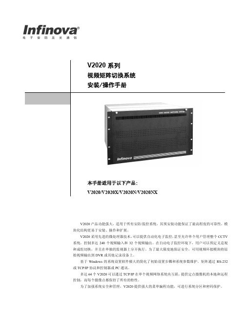
V2020A系列产品采用了ARM9微处理器技术,使用LINUX操作系统内核,可实现安防自动化,单机箱可支持最多240路视频输入和16路视频输出(或采用密集型机箱最多达到112路视频输入和32路视频输出)。
V2020A系列产品功能强大,适用于所有安防系统。
其预配置功能,可确保最高的可靠性,模块化结构易于安装、操作和扩展。
V2020A代表了视频矩阵切换/控制系统的顶尖技术,具有很高的性价比。
用户可预定义系统巡视,成组切换,事件定时器,报警显示/清除模式。
这些预定义功能可以分别在单个监视器上执行。
基于Windows的系统设置软件大大简化了初始安装过程和方便了后续系统参数维护。
矩阵切换/控制系统通过RS-232数据与控制器或PC机进行通信。
联网系统采用中心联网方式,由中心矩阵统一配置管理,非中心矩阵可通过网络从中心矩阵下载配置信息,真正实现了联网系统的分布式部署集中式管理。
配套的GUI软件提供的虚拟屏幕操作键盘,具有V2116系统键盘所有功能,更简化了系统操作。
系统具有网络通讯加密功能,确保网络通讯安全。
V2020系列中型矩阵切换/控制系统
单个标准机箱
240路视频输入,16路视频输出 单个密集型机箱 112路视频输入,32路视频输出 系统最大容量 240路视频输入,32路视频输出 视频输入 1.0Vp-p 复合信号,75Ω,BNC 视频输出 1.0Vp-p 复合信号,75Ω,BNC 幅频特性 ±1.0 dB (5.8 MHz) 微分增益 <1.0% (典型值) 微分相位 <1.5°(典型值) 信噪比 ≥60dB (典型值) 相邻通道串扰 PAL: 55dB (4.43MHz) NTSC: 55dB (3.58MHz) 输入到输入串扰 PAL: 70dB (4.43MHz) NTSC: 70dB (3.58MHz) 回程损耗(输入/输出) >40dB DC 电平 0V 或400mV 带宽 5Hz~8MHz 切换速度 20ms(典型值) 非易失存储体 可存储10年 通用巡视 128个 成组切换 128个 定时事件 35个
报警输入
最大支持1024路,串口或网络报警输入 报警响应
5种报警显示模式
3种报警清除模式 5张报警联动表
屏幕显示项 摄像机地址,日期/时间,监视器状态,摄像机标题(最多16个汉字或英文字符) 菜单语言 中文或英文 键盘控制时间 60ms (典型值) 键盘通信协议 RS-232或以太网 RS-232端口 8个,RJ-45 以太网端口 1个,RJ-45 以太网数据速率 10/100 Mbps 高速数据线 2个BNC 连接器 外同步输入输出 BNC 连接器 编程监视器 BNC 连接器 电源 100~240VAC 自适应 功率 最大120W
机箱尺寸 高266mm ×宽483mm ×深457mm 机箱包装尺寸 长635mm ×宽686mm ×高419mm 单机箱重量 23.1kg
单机箱运输重量 37.5 kg (以标准配置为例) 安装方式 19" EIA 标准机架安装 工作温度 0°C ~60°C
工作湿度
0~90%RH (无冷凝)
V2210网络集成控制软件V2116键盘。