海康威视终端设备说明书.docx
海康威视产品使用与管理指南说明书
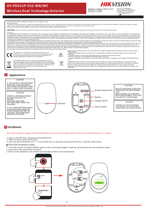
Disclaimer1Appearance2EnrollmentNote:The enrollment progress will be completed in3to10seconds normally,and the maximum enrollment duration is3minutes.1Enroll the Peripheral Locally1.Log in to the APP Store,download and install Hik-Pro.2.Power on the security control panel.3.Log in the APP and tap the icon"+".Scan the QR code or input the control panel serial No.to add the control panel.1.In the APP,tap the"Enrollment Mode"button on the control panel page to make the control panel enter the enrollment status.2.Loosen the screw and remove rear panel.3.Power on the peripheral,and it will be automatically enrolled to the control panel.CAUTIONRISK OF EXPLOSION IF BATTERYIS REPLACED BY AN INCORRECTTYPE.REPLACEMENT OF A BATTERYWITH AN INCORRECT TYPE THATCAN DEFEAT A SAFEGUARD.CAUTIONCHEMICAL BURNING DANGERDO NOT SWALLOW THEBATTERYKEEP NEW AND USEDBATTERIES AWAY FROM THECHILDREN.IF YOU THINK BATTERIES MIGHTHAVE BEEN SWALLOWED ORPLACED INSIDE ANY PART OFTHE BODY,SEEK IMMEDIATEMEDICAL ATTENTION.CAUTIONDISPOSE OF USED BATTERIESACCORDING TO THE INSTRUC-TIONS AND LOCAL REGULATION.CAUTIONIF THE BATTERY COMPARTMENTDOES NOT CLOSE SECURETLY,STOP USING THE PRODUCT ANDKEEP IT AWAY FROM CHILDREN.IndicatorBracket Tamper PortBatteryTamper SwitchPower SwitchEN50131-1:2006+A1:2009+A2:2017EN50131-2-4:2008EN50131-5-3:2017Security Grade(SG)2Environmental Class(EC)IICertified by Telefication1.Check SignalEnter the signal panel.Trigger the detector.Solid Green for 3s -Solid Orange for 3s Solid Red for 3s -Red light flashes for 2.Check the installation environmentNote:Hold the tamper button,and make the device power off and then power on for re-enrollment.3Installation2Enroll the Peripheral with QR and serialNo.1.In the APP ,tap the icon "+"and scan the QR code or serial No.on the peripheral.2.Loosen the screw and remove rear panel.3.Power on the peripheral,and it will be automatically enrolled to the control panel.3.Install the DetectorNote:The additional force shall be equal to three times the weight of the equipment but not less than 50N.The equipment and its associated mounting means shall remain secure during the installation.After the installation,the equipment,includingany associated mounting plate,shall not be damaged.with Screwsa.Knock out the screw holes on the rear panel.with the Sponge TapePaste the device on the wall with sponge tape.b.Secure the rear panel on the wall with four screws.Bracket InstallationCeiling Bracket Fitting (Non EN compliant)Wall Bracket Fitting4TestDetector zones and planesThe zones and plans of the PIRCAM are shown below.10m12m1m2m 4m6m8m85.9°(a)Detection Range 52zones 4planes6Operation Caution and Device Maintenance-All the electronic operation should be strictly compliance with the electrical safety regulations,fire prevention regulations and other related regulations in your local region.-Do not drop the device or subject it to physical shock,and do not expose it to high electromagnetism radiation.Avoid the equipment installation on vibrations surface or places subject to shock (ignorance can cause equipment damage).-Please make sure that the power has been disconnected before you wire,install or dismantle the device.-If smoke,odors or noise rise from the device,turn off the power at once and unplug the power cable,and then please contact the service center.-Do not drop the device or subject it to physical shock,and do not expose it to high electromagnetism radiation.Avoid the equipment installation on vibrations surface or places subject to shock (ignorance can cause equipment damage).-Do not place the device in extremely hot (refer to the specification of the device for the detailed operation temperature),cold,dusty or damp locations,and do not expose it to high electromagnetic radiation.-The device for indoor use shall be kept from rain and moisture.Exposing the equipment to direct sun light,low ventilation or heat source such as heater or radiator is forbidden (ignorance can cause fire danger).-Do not aim the device at the sun or extra bright places.A blooming or smear may occur otherwise (which is not a malfunction however),and affecting the endurance of sensor at the same time.-Improper use or replacement of the battery may result in hazard of explosion.Replace with the same orequivalent type only.Dispose of used batteries according to the instructions provided by the battery manufactur-er.-Do not expose the device to the corrosive gas.Otherwise the equipment damage may occur.-Do not expose the device to the explosive situation.The detector will enter the walk test mode (3minutes)after being enrolled.Trigger the detector within the detection range.If the LED indicator turns blue,the installation position is properly.If the LED indicator is still off,adjust the position of the detector.5FormattingHold the tamper switch for 8s and power the device on at the same time.The red LED flashes 3times when the formatting operation is completed.7Specification。
海康威视用户使用手册

海康威视⽤户使⽤⼿册⽬录1 产品介绍 (5)1.1 产品概述 (5)1.2 产品主要功能 (5)2安装说明 (8)2.1 清点设备及其附件 (8)2.2 安装硬盘 (8)2.3 后⾯板物理接⼝说明 (9)2.3.1 HC、HT、HF后⾯板说明 (9)2.3.2 1/2/3/4路HC及2路HT设备的后⾯板说明 (10) 2.3.3 HS设备的后⾯板说明 (11)2.4 报警线连接说明 (14)3 操作必读 (15)3.1 前⾯板说明 (15)3.2 遥控器说明 (19)3.3 菜单项说明 (21)3.3.1 菜单导航 (21)3.3.2 菜单操作⽅法 (22)3.4 输⼊法说明 (23)4 基本操作指南 (24)4.1 开机 (24)4.2 预览 (24)4.3 登录及修改⽤户名密码 (25)4.4 云台控制 (27)4.5 ⼿动录像 (28)4.6 回放 (29)4.7 录像资料备份 (32)4.8 语⾳对讲 (34)4.9 辅⼝输出控制 (34)4.10 关机 (35)5参数设置操作指南 (36)5.1 管理员及其密码 (36)5.2 创建与删除⽤户 (37)5.3 修改设备名称与设备号 (40)5.4 视频输出制式与VGA设置 (40)5.5 OSD设置 (41)5.6 视频输⼊参数设置 (43)5.7 区域遮盖设置 (44)5.8 遮挡报警处理 (45)5.9 视频丢失处理 (46)5.10 移动侦测处理 (48)5.11 本地预览属性设置 (51)5.12 录像参数及录像计划表 (53)5.13 报警输⼊输出设置 (57)5.14 ⽹络参数 (60)5.15 解码器 (61)5.16 串⼝参数设置 (64)5.17 异常处理 (68)5.18 交易信息 (69)6 管理⼯具 (71)6.1 保存设置 (71)6.2 恢复出⼚设置 (72)6.3 升级 (72)6.4 硬盘管理 (72)6.5 清除报警 (72)6.6 重新启动 (72)6.7 关机 (73)6.8 ⽇志 (73)6.8.1 按类型查询 (73)6.8.2 按时间查询 (74)6.8.3 按类型&时间查询 (74)6.9 查看系统信息 (74)7 ⽹络硬盘录像机软件升级 (75)7.1 配置FTP服务 (75)7.2 升级⽅式 (76)附录1 安装硬盘总容量的参考计算⽅法 (77)附录2 设备连接线的制作⽅法 (78)1 RS-485连接线制作⽅法 (78)2 UTP⽹络连接线制作⽅法 (78)3 RS-232连接线制作⽅法 (79)附录3 技术指标 (82)附录4 常⽤功能速查表 (83)附录5 常见故障解答 (85)1 产品介绍1.1 产品概述本设备是专为安防领域设计的⼀款优秀的数字监控产品。
海康威视简易说明书完整版

海康威视简易说明书 HUA system office room 【HUA16H-TTMS2A-HUAS8Q8-HUAH1688】海康威视iVMS-4200操作说明书前言非常感谢您购买我公司的产品,如果您有什么疑问或需要请随时联系我们。
适用型号本手册适用于网络视频监控软件iVMS-4200。
声明本手册可能包含技术上不准确的地方,或与产品功能及操作不相符的地方,或印刷错误。
我司将根据产品功能的增强或变化而更新本手册的内容,并将定期改进及更新本手册中描述的软硬件产品。
更新的内容将会在本手册的新版本中加入,恕不另行通知。
本手册中内容仅为用户提供参考指导作用,不保证与实物完全一致,请以实物为准。
约定在本手册中为了简化描述,做以下约定:网络视频监控软件iVMS-4200简称为软件。
网络硬盘录像机、、视频服务器、NVR、IP Camera和IP Dome等统一称为设备。
. iVMS-4200 简介. 功能概述软件iVMS-4200是为嵌入式网络监控设备开发的软件应用程序,适用于嵌入式网络硬盘录像机、混合型网络硬盘录像机、网络视频服务器、NVR、IP Camera、IP Dome、PCNVR和解码设备以及视音频编解码卡,支持实时预览、远程配置设备参数、录像存储、远程回放和下载等多种功能。
iVMS-4200具有以下特点:界面容器化处理模式:在客户端组件的界面设计上,精心采用容器化处理,简化了多屏和单屏切换的处理方式,大幅改善多屏操作感受,适应了一机多屏的PC发展趋势。
通道化管理模式:在客户端组件设计中,加入了通道化管理模式,抛开了以设备为核心主体的传统设计方式,更加适应于IP监控的发展方向。
用户体验为重心的界面设计:提供图片式可视化控制面板,以用户体验为重心,颠覆式的采用所需即可用的模式,提供一个功能的多个入口,以期达到最大限度减少用户操作步骤的目标。
需要才可见的显示方式:在客户端组件的界面元素上,加入了需要才可见的显示方式,在日历,时间条,工具栏,系统信息栏等多处,加入该设计模式,最大限度的节省有限的屏幕显示空间。
海康威视DS-3S系列HD-SDI光端机用户手册说明书

DS-3S系列综合平台HD-SDI光端机用户手册杭州海康威视数字技术股份有限公司技术热线:400-700-5998UD.6L0103D0063A01非常感谢您购买我司产品,如您有任何疑问或需求请随时联系我们。
本手册适用于以下产品:本手册可能包含技术上不准确的地方、或与产品功能及操作不相符的地方、或印刷错误。
我司将根据产品功能的增强或变化而更新本手册的内容,并将定期改进及更新本手册中描述的软硬件产品。
更新的内容将会在本手册的新版本中加入,恕不另行通知。
本手册中内容仅为用户提供参考指导作用,不保证与实物完全一致,请以实物为准。
本手册中提到的部件、组件和附件仅作说明之用,不代表购买机型的配置,详细配置请以装箱单为准。
0100001021128安全使用注意事项此内容的目的是确保用户正确使用本产品,以避免危险或财产损失。
在使用此产品之前,请认真阅读此说明手册并妥善保存以备日后参考。
如下所示,预防措施分为“警告”和“注意”两部分:警告:无视警告事项,可能会导致死亡或严重伤害。
注意:无视注意事项,可能会导致伤害或财产损失。
事项提醒用户防范潜在的死亡或严重伤害危险。
事项提醒用户防范潜在的伤害或财产损失危险。
警告在本产品安装使用中,必须严格遵守国家和使用地区的各项电气安全规程。
请使用正规厂家提供的电源适配器,供电电源要求为DC12V/1A。
在接线、拆装等操作时请一定要将电源断开,切勿带电操作。
如果设备工作不正常,请联系购买设备的商店或最近的服务中心,不要以任何方式拆卸或修改设备。
(对未经认可的修改或维修所导致的问题,本公司不承担责任)。
光端机的光器件所产生的光源能对人的眼睛产生永久性伤害,切勿用眼睛直视光端机的光器件和通电状态下光端机的光纤接口。
在光端机上插拔光纤时,切断电源。
注意请不要使物体摔落到设备上或大力震动设备,并使设备远离存在磁场干扰的地点。
避免将设备安装到表面震动或容易受到冲击的地方。
(忽视此项可能会损坏设备)请不要在高温(超过75℃)或低温(低于-40℃)或高湿度地点安装设备。
海康威视产品说明书

FOBS-10 FOBS-20 FOBS-30 Accessories FOB100-SOFT HHTFO-101-WM HHTFO-101-EC
The HHTFO-101 comes with a built-in flash card data logging feature allowing user to save collected data directly onto a high capacity SD flash card. SD cards of up to 1 GB capacity are supported. The data can be accessed through any PC equipped with a flash card reader. The HHTFO-101 also features the SnapLog feature which
Enclosure Protection: IP54 standard
Connectors: Optical: 1 ST connector Serial: DB-9 Power-In: Power jack connector SD Card: Push-to-eject card slot on top panel Batteries: Battery access port on bottom side
The HHTFO-101 is a valuable monitoring tool for a wide range of applications in energy, industrial and research activities, such as hot spot monitoring inside power transformers during manufacturing and heat runs. It can also be used in various high voltage applications and MW/RF heating applications.
海康威视DVR设备操作手册说明书

Step 17. Enter Alarm 1 Enable/Disable Submenu Press d to display flashing DSBL / ENBL .Step 18. Enable Alarm 1 SubmenuIf flashing ENBL is displayed, press a , if DSBL is displayed,press b until ENBL is displayed, then press d to store and go to the next menu item.Step 19. Select the Deviation Control Type Submenu Press d . If flashing _DEV Deviation is displayed press a ,otherwise press b until flashing _DEV is shown. Now press d to store and go to next menu item.Step 20. Select the Latched Type SubmenuPress d . If flashing UNLT Unlatched is displayed press a ,otherwise press b until UNLT is displayed.Press d to store and advance to next menu item.Step 21. Select the Normally Open Type of Contact Closure SubmenuPress d . If flashing N.o.Normally Open is displayed,press a , otherwise press b until N.o.is displayed. Press d to store and advance to next menu item.Step 22. Select the Above Type of Active Submenu Press d . If flashing ABoV Above is displayed, press a ,otherwise press b until ABoV is displayed. Press d to store and advance to next menu item.Step 23. Enable Alarm 1 at Power On (A.P.oN )Press d . If flashing ENBL is displayed, press a , otherwise press b until ENBL is displayed. Press d to store and advance to next menu item.Step 24. Enter Alarm 1 High SubmenuPress a twice to skip ALR.L Alarm 1 Low value. ALR.L is for below & ALR.H for above.Step 25. Set the Alarm 1 High value (ALR.H )Press d . Press b or c until value to set the display to 002.0. Press d to save.Step 26. Enter the Alarm 2 MenuThe display will show ALR2the top menu for Alarm 2.Repeat steps from 17 to 25 to set for Alarm 2 the same conditions as for Alarm 1.Step 27. Skip the Loop Break Time Menu (LOOP )Press a to go to the OUT1Output 1 Menu item.Step 28. Configuration the Output 1 MenuSet Alarm 1 Disabled (Step 18) to be able to Enable Output 1.Step 29. Configuration of Display Color Selection Press a until the COLR Display Color Selection Menu appears on the Display. Configure COLR as N.CLR /GRN (green), 1.CLR / RED (red), 2.CLR /AMBR (amber). Please refer to the operator’s manual if needed.For color change on Setpoints refer to Owners Manual Section 2.MQS4007/0411SPECIFICATIONSENSOR SPECIFICATIONSRelative Humidity Accuracy/Range:±2% for 10 to 90%±3% for 5 to 10% and 90 to 95%±4% for 0 to 5% and 95 to 100%Non-linearity : ±3%Hysteresis: ±1% RH Response Time :8 sec, tau 63%Repeatability : ±0.1%Resolution : 0.1%, 12bitTemperature Accuracy/Range*:±0.5°C for 5 to 45°C (±1°F for 41 to 113°F); up to ±1.5°C for -40 to 5°C and 45 to 124°C (up to ±2.7°F for -40 to 41°F and 113 to 257°F)*NOTE:extended temp range is for Probe only, the Controller’s operating temp is 0-50°CResponse Time : 5 to 30 sec, tau 63%Repeatability : ±0.1°C Resolution : 0.1°C, 14 bit METER SPECIFICATIONS Display:4-digit, 9-segment LED, •10.2 mm (0.40")Red, green, and amber programmable colors for setpoint and temperature units.Output 1†:Relay 250 Vac @ 3 A Resistive Load,SSR, Pulse Output 2†:Relay 250 Vac @ 3 A Resistive Load,SSR, Pulse †Only with -AL Limit Alarm optionOptions:Communication RS-232 / RS-485or Excitation:24 Vdc @ 25 mAExc. not available for Low Power OptionLine Voltage/Power:90 - 240 Vac ±10%,50 - 400 Hz*, or 110 - 375 Vdc, 4 W* No CE compliance above 60 HzLow Voltage Power Option:12 - 36 Vdc or 24 Vac** ±10%, 3 W**Units can be powered safely with 24 Vac but No Certification for CE/UL are claimed.Dimensions:25.4 H x 48 W x 126.3 D mm (1.0 x 1.89 x 5")Weight:127 g (0.28 lb)Approvals:CE per EN61010-1:2001It is the policy of OMEGA to comply with all worldwide safety and EMC/EMI regulations that apply.OEMGA is constantly pursuing certification of its products to the European New Approach Directives.OMEGA will add the CE mark to every appropriate device upon certification.The information contained in this document is believed to be correct, but OMEGA Engineering,Inc.accepts no liability for any errors it contains, and reserves the right to alter specifications without notice.TRADEMARK NOTICE:®,®,, andare Trademarks ofOMEGA ENGINEERING, INC.®This Quick Start Reference provides informationon setting up your instrument for basic operation.The latest complete Communication and OperationalManual as well as free Software and ActiveX Controlsare available at /specs/iseriesor on the CD-ROM enclosed with your shipment. SAFETY CONSIDERATIONThe instrument is a panel mount device protected in accordance with EN61010-1:2001. Remember that the unit has no power-on switch. Building installation should include a switch or circuit-breaker that must be compliant to IEC 947-1 and 947-3.SAFETY:•Do not exceed voltage rating on the label located onthe top of the instrument housing.•Always disconnect power before changing signal andpower connections.•Do not use this instrument on a work bench withoutits case for safety reasons.•Do not operate this instrument in flammable orexplosive atmospheres.•Do not expose this instrument to rain or moisture. EMC:•Whenever EMC is an issue, always use shielded cables.•Never run signal and power wires in the same conduit.•Use signal wire connections with twisted-pair cables.•Install Ferrite Bead(s) on signal wire close to theinstrument if EMC problems persist.MOUNTINGPanel Mounting Instruction:ing the dimensions from the panel cutout diagramshown above, cut an opening in the panel.2.Insert the unit into the opening from the front of thepanel, so the gasket seals between the bezel and thefront of the panel.3.Slide the retainer over the rear of the case and tightenagainst the backside of the mounting panel.。
海康威视 网络视频录像机 用户手册说明书

网络视频录像机用户手册V3.01目录关于本文档 (1)1 操作必读 (2)1.1 本地操作必读 (2)1.2 本地界面操作方法 (2)2 初始配置 (5)2.1 开机准备 (5)2.2 自动添加 (5)2.3 设备登录 (6)2.4 开机向导 (9)3 预览 (11)3.1 预览界面状态 (12)3.2 窗格工具栏 (12)3.3 底部工具栏 (13)3.4 右键菜单栏 (17)4 通道配置 (20)4.1 通道管理 (20)4.1.1 IPC配置 (20)4.1.2 鱼眼配置 (27)4.1.3 高级配置 (29)4.2 编码参数 (30)4.3 音频配置 (32)4.4 抓图参数 (33)4.5 OSD配置 (34)4.6 图像参数 (35)4.7 隐私遮盖 (39)4.8 云台配置 (41)5 智能分析 (46)5.1 智能功能配置 (46)5.1.1 联动方式 (47)5.1.2 布防计划 (54)5.1.3 人脸检测 (55)5.1.4 人脸比对 (57)5.1.5 越界检测 (60)5.1.6 区域入侵 (63)5.1.7 进入区域 (65)5.1.8 离开区域 (67)5.1.9 智能运动检测 (69)5.1.11 高空抛物 (71)5.1.12 虚焦检测 (73)5.1.13 场景变更 (73)5.1.14 物品搬移 (74)5.1.15 物品遗留 (75)5.1.16 自动跟踪 (76)5.1.17 人流量统计 (77)5.1.18 人员密度检测 (78)5.2 分析器配置 (80)5.3 名单库管理 (80)5.3.1 人脸名单 (80)5.4 车辆管控 (83)5.4.1 车牌名单 (83)5.4.2 车辆报警布控 (85)5.5 智能检索 (86)5.5.1 人脸抓拍检索 (86)5.5.2 人脸比对检索 (87)5.5.3 以图搜图 (90)5.5.4 车辆检索 (93)5.5.5 行为检索 (95)5.5.6 人数统计报表 (98)5.6 智能预览 (99)6 网络配置 (104)6.1 常规配置 (104)6.1.1 网络配置 (104)6.1.2 宇视云 (105)6.1.3 DDNS (109)6.1.4 邮件 (110)6.2 平台配置 (111)6.2.1 国标服务器配置 (111)6.2.2 国标本地配置 (114)6.2.3 UNP (114)6.2.4 监管平台 (116)6.2.5 SNMP (117)6.2.6 报警上报 (119)6.2.7 视图库GA/T1400本地配置 (120)6.2.8 视图库GA/T1400服务器配置 (121)6.2.9 CDN(流分发)管理 (122)6.2.10 TMS配置 (123)6.3 高级配置 (124)6.3.1 拨号上网 (124)6.3.2 端口 (125)6.3.3 端口映射 (126)6.3.4 组播 (127)6.3.5 FTP (128)6.4 无线局域网 (130)7 系统配置 (130)7.1 基本配置 (130)7.2 预览配置 (131)7.2.1 预览配置 (131)7.2.2 高级配置 (134)7.3 时间配置 (134)7.3.1 时间配置 (134)7.3.2 时间同步 (135)7.3.3 假日配置 (135)7.4 POS配置 (137)7.4.1 POS显示配置 (137)7.4.2 POS配置 (138)7.5 串口配置 (140)7.6 用户配置 (141)7.7 安全配置 (142)7.7.1 IP地址过滤 (142)7.7.2 ONVIF认证 (143)7.7.3 802.1x (143)7.7.4 ARP防攻击 (144)7.7.5 视频水印 (144)7.7.6 安全密码 (144)7.8 热备配置 (145)8 备份 (147)8.1 录像备份 (147)8.2 图片备份 (150)9 存储配置 (153)9.1 录像计划 (153)9.2 抓图计划 (156)9.3 阵列配置 (157)9.4 硬盘管理 (161)9.5 盘组配置 (163)9.6 容量配置 (164)9.7 高级配置 (165)10 报警配置 (166)10.1 运动检测 (166)10.2 遮挡检测 (167)10.3 人形检测 (167)10.4 视频丢失 (168)10.5 输入输出 (169)10.5.1 报警输入 (169)10.5.2 报警输出 (171)10.6 热成像检测 (173)10.7 温度异常 (175)10.8 异常配置 (176)10.9 声音检测 (177)10.10 蜂鸣器 (178)10.11 门铃呼叫 (179)10.12 滞留人数告警 (179)10.13 一键撤防 (181)10.14 手动报警 (183)11 系统维护 (184)11.1 系统信息 (184)11.1.1 基本信息 (184)11.1.2 通道状态 (184)11.1.3 录像状态 (185)11.1.4 在线用户 (185)11.1.5 硬盘状态 (186)11.1.6 解码卡状态 (186)11.2 网络信息 (187)11.2.1 网络流量 (187)11.2.2 网络抓包 (187)11.2.3 网络检测 (189)11.2.4 网络状态 (191)11.2.5 网络资源统计 (191)11.2.6 PoE/交换网口状态 (192)11.3 日志查询 (192)11.4 系统备份 (194)11.4.1 系统备份 (194)11.4.2 诊断信息 (194)11.5 系统恢复 (196)11.6 自动维护 (196)11.7 系统升级 (196)11.7.1 NVR升级 (197)11.7.2 IPC升级 (198)11.8 硬盘检测 (199)11.8.1 S.M.A.R.T.检测 (199)11.8.2 磁盘检测 (200)11.9 关于我们 (200)11.10 一键收集 (201)12 回放 (201)12.1 即时回放 (202)12.2 普通回放 (202)12.3 智能回放 (204)12.4 走廊回放 (206)12.5 外部文件回放 (206)12.6 标签回放 (206)12.7 检索回放 (208)12.8 文件管理 (209)13 关机 (210)14 Web操作 (210)14.1 登录前准备 (210)14.2 登录 (211)14.3 实况 (211)14.4 回放 (212)14.5 配置 (213)14.6 智能 (214)15 附录:常见问题解答 (214)关于本文档版权声明©2022浙江宇视科技有限公司。
杭州海康威视数字技术有限公司 DS-TPE100 控制终端用户手册说明书

Control Terminal- TPE100User ManualUD.6L0201D1989A01User ManualCOPYRIGHT ©2015 Hangzhou Hikvision Digital Technology Co., Ltd.ALL RIGHTS RESERVED.Any and all information, including, among others, wordings, pictures, graphs are the properties of Hangzhou Hikvision Digital Technology Co., Ltd. or its subsidiaries (hereinafter referred to be “Hikvision”). This user manual (hereinafter referred to be “the Manual”) cannot be reproduced, changed, translated, or distributed, partially or wholly, by any means, without the prior written permission of Hikvision. Unless otherwise stipulated, Hikvision does not make any warranties, guarantees or representations, express or implied, regarding to the Manual.About this ManualThis Manual is applicable to Control Terminal DS-TPE100.The Manual includes instructions for using and managing the product. Pictures, charts, images and all other information hereinafter are for description and explanation only. The information contained in the Manual is subject to change, without notice, due to firmware updates or other reasons. Please find the latest version in the company website (/en/).Please use this user manual under the guidance of professionals.Trademarks Acknowledgementand other Hikvision’s trademarks and logos are the properties of Hikvision in various jurisdictions. Other trademarks and logos mentioned below are the properties of their respective owners.Legal DisclaimerTO THE MAXIMUM EXTENT PERMITTED BY APPLICABLE LAW, THE PRODUCT DESCRIBED, WITH ITS HARDWARE, SOFTWARE AND FIRMWARE, IS PROVIDED “AS IS”, WITH ALL FAULTS AND ERRORS, AND HIKVISION MAKES NO WARRANTIES, EXPRESS OR IMPLIED, INCLUDING WITHOUT LIMITATION, MERCHANTABILITY, SATISFACTORY QUALITY,FITNESS FOR A PARTICULAR PURPOSE, AND NON-INFRINGEMENT OF THIRD PARTY. IN NO EVENT WILL HIKVISION, ITS DIRECTORS, OFFICERS, EMPLOYEES, OR AGENTS BE LIABLE TO YOU FOR ANY SPECIAL, CONSEQUENTIAL, INCIDENTAL, OR INDIRECT DAMAGES, INCLUDING, AMONG OTHERS, DAMAGES FOR LOSS OF BUSINESS PROFITS, BUSINESS INTERRUPTION, OR LOSS OF DATA OR DOCUMENTATION, IN CONNECTION WITH THE USE OF THIS PRODUCT, EVEN IF HIKVISION HAS BEEN ADVISED OF THE POSSIBILITY OF SUCH DAMAGES.REGARDING TO THE PRODUCT WITH INTERNET ACCESS, THE USE OF PRODUCT SHALL BE WHOLLY AT YOUR OWN RISKS. HIKVISION SHALL NOT TAKE ANY RESPONSIBILITES FOR ABNORMAL OPERATION, PRIVACY LEAKAGE OR OTHER DAMAGES RESULTING FROM CYBER ATTACK, HACKER ATTACK, VIRUS INSPECTION, OR OTHER INTERNET SECURITY RISKS; HOWEVER, HIKVISION WILL PROVIDE TIMELY TECHNICAL SUPPORT IF REQUIRED.SURVEILLANCE LAWS VARY BY JURISDICTION. PLEASE CHECK ALL RELEVANT LAWS IN YOUR JURISDICTION BEFORE USING THIS PRODUCT IN ORDER TO ENSURE THAT YOUR USE CONFORMS THE APPLICABLE LAW. HIKVISION SHALL NOT BE LIABLE IN THE EVENT THAT THIS PRODUCT IS USED WITH ILLEGITIMATE PURPOSES.IN THE EVENT OF ANY CONFLICTS BETWEEN THIS MANUAL AND THE APPLICABLE LAW, THE LATER PREVAILS.Regulatory InformationFCC InformationFCC compliance: This equipment has been tested and found to comply with the limits for a digital device, pursuant to part 15 of the FCC Rules. These limits are designed to provide reasonable protection against harmful interference when the equipment is operated in a commercial environment. This equipment generates, uses, and can radiate radio frequency energy and, if not installed and used in accordancewith the instruction manual, may cause harmful interference to radio communications. Operation of this equipment in a residential area is likely to cause harmful interference in which case the user will be required to correct the interference at his own expense.FCC ConditionsThis device complies with part 15 of the FCC Rules. Operation is subject to the following two conditions:1. This device may not cause harmful interference.2. This device must accept any interference received, including interference that may cause undesired operation.EU Conformity StatementThis product and - if applicable - the supplied accessories too aremarked with "CE" and comply therefore with the applicableharmonized European standards listed under the EMC Directive 2004/108/EC, the RoHS Directive 2011/65/EU.2012/19/EU (WEEE directive): Products marked with this symbolcannot be disposed of as unsorted municipal waste in the EuropeanUnion. For proper recycling, return this product to your localsupplier upon the purchase of equivalent new equipment, or dispose of it at designated collection points. For more information see: .2006/66/EC (battery directive): This product contains a battery thatcannot be disposed of as unsorted municipal waste in the EuropeanUnion. See the product documentation for specific batteryinformation. The battery is marked with this symbol, which may include lettering to indicate cadmium (Cd), lead (Pb), or mercury (Hg). For proper recycling, return the battery to your supplier or to a designated collection point. For more information see: .Industry Canada ICES-003 ComplianceThis device meets the CAN ICES-3 (A)/NMB-3(A) standards requirements.Safety InstructionThese instructions are intended to ensure that the user can use the product correctly to avoid danger or property loss.The precaution measure is divided into ‘Warnings’ and ‘Cautions’:Warnings: Serious injury or death may be caused if any of these warnings are neglected.Cautions: Injury or equipment damage may be caused if any of these cautions are neglected.Follow theseprevent serious injury or death. Follow these potential injuryWarnings:●Do not drop the device or subject it to physical shock.●Proper configuration of all passwords and other security settings is theresponsibility of the installer and/or end-user.●In the use of the product, you must be in strict compliance with the electricalsafety regulations of the nation and region. Please refer to technical specifications for detailed information.●Input voltage should meet both the SELV (Safety Extra Low V oltage) and theLimited Power Source with 100~240 V AC, 48 VDC or 12 VDC according to the IEC60950-1 standard. Please refer to technical specifications for detailed information.●Do not connect several devices to one power adapter as adapter overload maycause over-heating or a fire hazard.●Please make sure that the plug is firmly connected to the power socket.●If smoke, odor or noise rise from the device, turn off the power at once andunplug the power cable, and then please contact the service center.Cautions:●Read the manual carefully before you use the device.●Make sure the device power is turned off and the plug is unplug from the powersocket when you do the operations, including plug or remove the board card.●Make sure the device power is turned off when plug or unplug any cables.●Wait at least 30 seconds to power on the device if the device is newly shut downto avoid the device damage by frequent power off/power on.●For some precise unit is quite sensitive to the ESD, make sure electrostaticdischarge has been finished if you want to dismount or assemble the device.●If no ESD workbench is provided, you can follow the tips below to lower thedamage might be caused by ESD.o Wear a wrist strap, and touch the metal parts of the device with the wrist strap.o Touch the metal part on the machine instead of the components.o Avoid the unnecessary walking around.o Hold the edge of the components, especially for the board card.o Put all the components on a conducting foam pad.o Move the components on the workbench as less as possible.●It is recommended that you use a magnetic cross screwdriver to tighten or loosenthe screws. Make sure no tool or components are left in the machine.●Keep the device away from water and any liquid.●While shipping, the device should be packed in its original packing.●Improper use or replacement of the battery may result in hazard of explosion.●Ensure unit is installed in a well-ventilated, dust-free environment.●Ensure unit is properly secured to a rack or shelf. Major shocks or jolts to the unitas a result of dropping it may cause damage to the sensitive electronics within theunit.●Use the device in conjunction with an UPS if possible.●Power down the unit before connecting and disconnecting accessories andperipherals.● A factory recommended HDD should be used for this device.Table of ContentsChapter 1About This Manual (8)Chapter 2Introduction (9)2.1Product Overview (9)2.2Performance (9)2.3Specification (10)2.4Shipping & Storage Requirement (11)Chapter 3Installation (12)3.1Appearance (12)3.2Dimension (12)3.3Interface Description (13)3.4Assembling HDD (14)3.5Assembling the Device (15)Chapter 1About This Manual PurposeThis document introduces the DS-TPE100 Control Terminal and relevant settings of the product.Intended AudienceThis document is intended for:Technical support engineersMaintenance engineersChapter 2Introduction2.1Product OverviewWith the features of low consumption and high performance, DS-TPE100 is designed for entrance/exit control. Adopting the strong aluminum alloy extrusions without fans on its body, the control terminal has a compact structure with good heat dissipation. The control terminal is applicable to the challenging environment of dusty and high electromagnetic interference.Figure 2-1Overview of Control Terminal2.2PerformanceCPU:Intel® CPU Bay Trail-D J1900 with integrated MC and GPU.CS:Intel® CPU Bay Trail-D J1900Memory:4GB DDR3L, with memory frequency of 1333MHzEthernet Interface:10/100/1000Mbps Self-adaptiveDisplay:Integrated Graphics Processing UnitVGA, with max. resolution and fresh rate of 2560×1600@60HzHDMI, with max. resolution and fresh rate of 1920x1080@60HzAudio:Standard HD, support LINE-IN/LINE-OUTAvailable interfaces:2 10/100/1000Mbps Ethernet interfaces, and 4 10M/100Mbps Ethernet interfaces 4 USB2.0 interfaces2 RS485 interfaces3 RS232 interfaces1 VGA interface1 HDMI interface1 audio interface (LINE-in/Line-out)1 12V DC power inputOthers:3.5’ HDD(1 pcs),Adapter (60w)Consumption:40W at max.2.3SpecificationDimension & Weight:Dimension: 245mm(L)*170mm(W)*65mm(H)Weight: 4.05kgWorking Environment:Temperature: -20°C~55°CHumidity: 10%~90% (Non-condensation)Storing Environment:Temperature: -40°C~80°CHumidity: 10%~90% (Non-condensation)Electromagnetic compatibility:GB9254-2008, radiation disturbance (A), conducted disturbance(A)GB/T17626.2-2006 ESD (2)GB/T17626.4-2008 EFT (2)GB/T17626.5-2008SURGE(2)GB/T17626.6-2008CS (2)GB/T17626.11-2008, auto disconnected when voltage dip, voltage short circuit Reliability:MTBF≥50000hSafety:GB4943Environmental Suitability:Anti-vibration: 5-19Hz/1.0mm amplitude, 19-200Hz/1.0g accelerated speedShock Resistance: 10g accelerated speed, 11ms period2.4Shipping & Storage Requirement●ShippingIt is recommended that the device is packed in its original packing when shipping. Make sure the device is away from the flammable, combustible and corrosive objects, and the rain, snow, and liquid as well.●StoringIt is recommended that the device is packed in its original packing when storing. The ideal storing temperature is -40°C~80°C, and the ideal storing humidity is 10%~90%.Keep the device away from the flammable, combustible and corrosive objects, and the storing environment should be free of the strong mechanical resonance and strong magnetic.The device package should be underlay at least 10cm from the ground. And it should be at least 50cm away from the wall, heat source, cold source, and window or air inlet.Chapter 3Installation 3.1AppearanceThe device appearance is shown below.Figure 3-1Appearance3.2DimensionFigure 3-2Dimension3.3Interface Description12356478910111213151614Figure 3-3Interface Introduction Figure 3-4Interface Description3.4Assembling HDDFigure 3-5Assemble the HDDAssemble the HDD first before you install the HDD to the device.Steps:1.Align the copper foil to one side of the HDD, and fix the thermal pad to the motorpart.2.Fix the crash pads to the HDD radiator.3.Secure the HDD to the HDD radiator.4.Install the copper foil to the other side of the HDD.3.5Assembling the DeviceFront CoverFigure 3-6Main ComponentsSteps:1.Align the PCB board with the standoffs, and secure the PCB board by tighteningthe lock screws.2.Align the thermal module with the standoffs, and secure the thermal module withby tightening the lock screws.3.Install the HDD to the standoffs, and tighten the lock screws.4.Connect the HDD cables to the corresponding interfaces.5.Align the front cover to the interfaces of the PCB board, and tighten the lockscrews.6.Install the fixed strip, align the upper cover to the lower cover, and secure theupper cover and lower cover by tightening the lock screws.7.Install the grounding screws.。
- 1、下载文档前请自行甄别文档内容的完整性,平台不提供额外的编辑、内容补充、找答案等附加服务。
- 2、"仅部分预览"的文档,不可在线预览部分如存在完整性等问题,可反馈申请退款(可完整预览的文档不适用该条件!)。
- 3、如文档侵犯您的权益,请联系客服反馈,我们会尽快为您处理(人工客服工作时间:9:00-18:30)。
“手机看店”终端设备说明书(海康威视)中国电信浙江公司政企客户部2013年9月终端设备说明书(海康威视)目录第1章CDX11.1 产品特性网络摄像机是集传统的模拟摄像机和网络视频服务器于一体的嵌入式数字监控产品。
采用嵌入式操作系统和高性能硬件处理平台,系统调度效率高,代码固化在Flash中,体积小,具有较高稳定性和可靠性,其主要特性如下:●采用先进的视频压缩技术,支持H.264/MPEG4/MJPEG多种编码方式,处理灵活,支持变码率,在设定视频图像质量的同时,也可限定视频图像的压缩码流。
●支持双码流,可使用手机监控。
●多种报警功能:移动侦测、遮挡报警、网线断、IP地址冲突、存储器满、存储器错。
●支持TCP/IP,HTTP,DHCP,DNS,RTP,RTSP,PPPoE,SMTP,NTP, ICMP, IGMP, SNMP,FTP, 802.1x, QoS, UPnP, HTTPS等协议。
●支持通过客户端软件或IE浏览器实时浏览视频、设置参数、查看网络摄像机状态,并可以通过网络实现报警联动和存储功能。
●支持网络远程升级,实现远程维护。
●支持Wi-Fi功能,实现无线连接(部分机型)。
●支持PIR人体侦测功能。
●支持无线声光报警,带无线收发功能。
支持无线门磁、无线遥控钥匙、无线遥控布防撤防功能。
1.2 外观介绍本系列网络摄像机由机身、三轴调节支架和底座组成,其外观结构和接口如下图所示:图1-1 外观示意图描述 说明网络接口 10M / 100M 自适应以太网口,支持PoE 供电电源接口 DC5V ±10%Micro SD 卡槽 支持Micro SD 卡本地存储 一键复位 RESET:一键恢复设备默认参数 人体感应(PIR )人体热释电红外探测器MIC 内置麦克风USB 接口 支持USB Wi-Fi 或3G 网卡Alarm 报警指示灯 Status 隐私屏蔽模式指示灯Link网络指示灯遥控器外观及说明如下:描述说明布防键报警布防撤防键报警撤防隐私保护键控制图像预览开启或停止1.3 技术参数型号参数 CDX1130万1/3”CMOS 多功能报警型网络摄像机摄像机 传感器类型 1/3” Progr essive Scan CMOS 最小照度 0.01 Lux @(F1.2,AGC ON), 0 Lux with IR快门 1/25秒至1/100,000秒镜头 4mm@ F2.0 水平视场角:68°镜头接口类型M12日夜转换模式ICR红外滤片式数字降噪数字降噪压缩标准视频压缩标准H.264 / MPEG4 / MJPEGH.264编码类型BaseLine Profile / Main Profile / High Profile 视频压缩码率32Kbps~16Mbps音频压缩标准G.711/G.726音频压缩码率64Kbps(G.711) / 16Kbps(G.726)图像最大图像尺寸1280 × 960帧率50Hz: 25fps (1280 × 960), 25fps (1280 × 720) 60Hz: 30fps (1280 × 960), 30fps (1280 × 720)图像设置亮度,对比度,饱和度,锐度等通过客户端或者浏览器可调背光补偿支持,可选择区域图片叠加支持128×128大小BMP 24位图像叠加,可选择区域网络功能存储功能支持Micro SD/SDHC卡(32G)断网本地存储,NAS(iSCSI可选)智能报警PIR人体侦测,无线门磁报警,移动侦测,动态分析,遮挡报警, 网线断,IP地址冲突,存储器满,存储器错支持协议TCP/IP,ICMP,HTTP,HTTPS,FTP,DHCP,DNS,DDNS,RTP,RTSP,RTCP, PPPoE,NTP,UPnP,SMTP,SNMP,IGMP,802.1X,QoS,IPv6,Bonjour(SIP,SRTP可选)接口协议ONVIF,PSIA,CGI通用功能一键恢复,防闪烁,双码流,心跳,镜像,密码保护,视频遮盖,水印技术,匿名访问,IP地址过滤接口通讯接口1个RJ45 10M/100M自适应以太网口口报警接口8路无线输入,1路无线输出(433MHz无线收发)无线参数(适用于支持Wi-Fi机型)无线标准IEEE802.11b, 802.11g, 802.11n Draft频率范围 2.4 GHz ~ 2.4835 GHz信道带宽支持20/40MHz安全64/128-bit WEP, WPA/WPA2, WPA-PSK/WPA2-PSK, WPS传输速率11b: 11Mbps11g: 54Mbps11n: 上限150Mbps一般规范工作温度和湿度-25℃~60℃,湿度小于95%(无凝结) 电源供应DC5V±10% / PoE功耗5W MAX红外可达10米PIR人体侦测侦测角度:80°侦测距离:8米尺寸(mm) 90 × 114 × 119.8重量500g1.4 安装1.安装贴纸:将安装贴纸粘贴到选定的天花板安装部位。
图1-2安装贴纸取下底座盖:将摄像机底座右滑盖和侧出线固定座沿图示方向取下来。
图1-3取下底座盖安装摄像机:将摄像机安装到天花板上,对照安装贴纸的安装孔位,拧紧固定螺钉,然后连接好网络线和电源线,并从出线孔导出线路;如果需要侧出线,取下侧出线固定座后,可从底座缺口处走线。
注意水泥墙面,需先安装膨胀螺钉,如果是木质墙面可使用自攻螺钉进行安装固定。
图1-4安装摄像机安装完成:重新装上底座盖,安装完成。
图1-5安装完成三轴调节说明:P,T方向旋转:支架拧松压紧螺母1,即可进行P、T方向的调节。
支架球头、支架球套、左固定盖球面接触,压紧螺母2与左固定盖螺纹连接;当松开压紧螺母1,支架球头与支架球套实现P方向350°的旋转,支架球头实现T方向的旋转,旋转角度为90°。
R方向旋转:拧松压紧螺母2,即可进行R方向的调节。
支架球头与前端组件中的后盖通过螺纹连接,压紧螺母2与前端组件后盖通过螺纹连接,前端组件在支架球头上进行360°的旋转;当拧紧压紧螺母2时,塑胶垫片挤压前端组件,R方向得到固定。
图1-6三轴调节门磁安装说明:图1-7门磁安装无线门磁由两部分组成:右侧较小的部件为磁块,左侧较大的部件是无线发射器。
无线发射器上有两个LED灯,上面的LED是发射指示灯,当发射无线信号时呈红色,下面的LED是低电压指示灯,当电池电量不足是呈绿色。
门磁安装:无线门磁一般安装在需要进行布防的门或窗内侧的上方。
以门安装为例,首先将磁块贴在门框上,并使用螺钉进行固定;然后使用强力贴纸将无线发射器粘贴在门上,并与磁块保持相对位置,无线发射器和磁块间隙应小于15mm。
第2章CDX1普通版2.1 产品特性网络摄像机是集传统的模拟摄像机和网络视频服务器于一体的嵌入式数字监控产品。
采用嵌入式操作系统和高性能硬件处理平台,系统调度效率高,代码固化在Flash中,体积小,具有较高稳定性和可靠性,其主要特性如下:采用先进的视频压缩技术,支持H.264/MPEG4/MJPEG多种编码方式,处理灵活,支持变码率,在设定视频图像质量的同时,也可限定视频图像的压缩码流。
●支持双码流,可使用手机监控。
●支持TCP/IP,HTTP,DHCP,DNS,RTP,RTSP,PPPoE,SMTP,NTP, ICMP, IGMP, SNMP,FTP, 802.1x, QoS, UPnP, HTTPS等协议。
●支持通过客户端软件或IE浏览器实时浏览视频、设置参数、查看网络摄像机状态,并可以通过网络实现存储功能。
●支持网络远程升级,实现远程维护。
●支持Wi-Fi功能,实现无线连接。
2.2 外观介绍本系列网络摄像机由机身、三轴调节支架和底座组成,其外观结构和接口如下图所示:图2-8外观示意图描述说明网络接口10M / 100M自适应以太网口,支持PoE供电电源接口DC5V±10%Micro SD卡槽支持Micro SD卡本地存储一键复位RESET:一键恢复设备默认参数人体感应(PIR)人体热释电红外探测器MIC 内置麦克风USB接口支持USB Wi-Fi或3G网卡Alarm 报警指示灯Status 隐私屏蔽模式指示灯Link 网络指示灯2.3 技术参数型号参数CDX1普通版130万1/3”CMOS网络摄像机摄像机传感器类型1/3” Progr essive Scan CMOS最小照度0.02Lux @(F1.2,AGC ON), 0 Lux with IR 快门1/25秒至1/100,000秒镜头4mm@ F2.0 水平视场角:68°镜头接口类型M12日夜转换模式ICR红外滤片式数字降噪数字降噪压缩标准视频压缩标准H.264 / MPEG4 / MJPEGH.264编码类型BaseLine Profile / Main Profile / High Profile 视频压缩码率32Kbps~16Mbps音频压缩标准G.711/G.726音频压缩码率64Kbps(G.711) / 16Kbps(G.726)图像最大图像尺寸1280 × 960帧率50Hz: 25fps (1280 × 960), 25fps (1280 × 720) 60Hz: 30fps (1280 × 960), 30fps (1280 × 720)图像设置亮度,对比度,饱和度,锐度等通过客户端或者浏览器可调背光补偿支持,可选择区域图片叠加支持128×128大小BMP 24位图像叠加,可选择区域网络功能存储功能支持Micro SD/SDHC卡(32G)断网本地存储,NAS(iSCSI可选)支持协议TCP/IP,ICMP,HTTP,HTTPS,FTP,DHCP,DNS,DDNS,RTP,RTSP,RTCP, PPPoE,NTP,UPnP,SMTP,SNMP,IGMP,802.1X,QoS,IPv6,Bonjour(SIP,SRTP可选)接口协议ONVIF,PSIA,CGI通用功能一键恢复,防闪烁,双码流,心跳,镜像,密码保护,视频遮盖,水印技术,匿名访问,IP地址过滤接口通讯接口1个RJ45 10M/100M自适应以太网口口无线参数无线标准IEEE802.11b, 802.11g, 802.11n Draft频率范围 2.4 GHz ~ 2.4835 GHz信道带宽支持20/40MHz安全64/128-bit WEP, WPA/WPA2, WPA-PSK/WPA2-PSK, WPS传输速率11b: 11Mbps11g: 54Mbps11n: 上限150Mbps一般规范工作温度和湿度-25℃~60℃,湿度小于95%(无凝结)电源供应DC5V±10% / PoE功耗5W MAX红外可达10米尺寸(mm) 90 × 114 × 119.8重量500g2.4 安装2.安装贴纸:将安装贴纸粘贴到选定的天花板安装部位。