AT89S52中文资料 单片机
单片机AT89S52介绍
AT89S52简介AT89S52是一个8位单片机,片内ROM全部采用FLASH ROM技术,与MCS-51系列完全兼容,它能以3V的超低电压工作,晶振时钟最高可达24MHz。
AT89S52是标准的40引脚双列直插式集成电路芯片,有4个八位的并行双向I/O端口,分别记作P0、P1、P2、P3。
第31引脚需要接高电位使单片机选用内部程序存储器;第9引脚是复位引脚,要接一个上电手动复位电路;第40脚为电源端VCC,接+5V电源,第20引脚为接地端VSS,通常在VCC和VSS引脚之间接μF高频滤波电容。
第18、19脚之间接上一个12MHz的晶振为单片机提供时钟信号。
AT89S52单片机说明如下:此芯片是一种高性能低功耗的采用CMOS工艺制造的8位微控制器,它提供下列标准特征:8K字节的程序存储器,256字节的RAM,32条I/O线,2个16位定时器/计数器, 一个5中断源两个优先级的中断结构,一个双工的串行口, 片上震荡器和时钟电路。
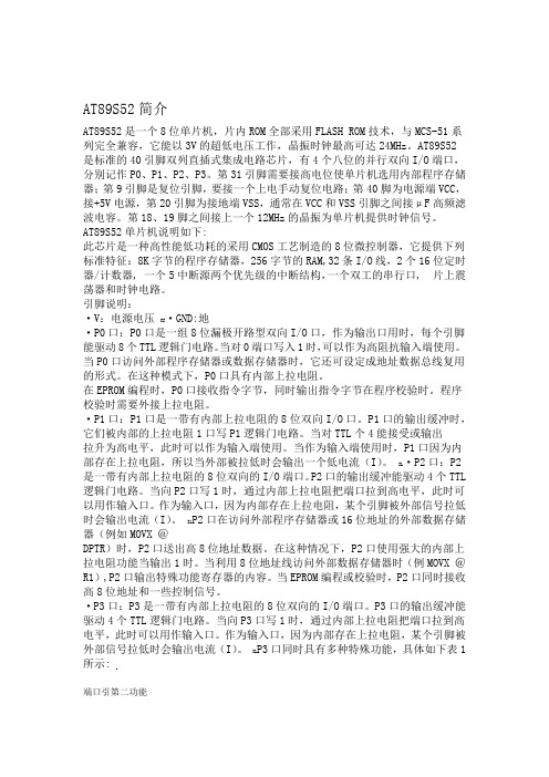
引脚说明:·V:电源电压CC·GND:地·P0口:P0口是一组8位漏极开路型双向I/O口,作为输出口用时,每个引脚能驱动8个TTL逻辑门电路。
当对0端口写入1时,可以作为高阻抗输入端使用。
当P0口访问外部程序存储器或数据存储器时,它还可设定成地址数据总线复用的形式。
在这种模式下,P0口具有内部上拉电阻。
在EPROM编程时,P0口接收指令字节,同时输出指令字节在程序校验时。
程序校验时需要外接上拉电阻。
·P1口:P1口是一带有内部上拉电阻的8位双向I/O口。
P1口的输出缓冲时,它们被内部的上拉电阻1口写P1逻辑门电路。
当对TTL个4能接受或输出拉升为高电平,此时可以作为输入端使用。
当作为输入端使用时,P1口因为内部存在上拉电阻,所以当外部被拉低时会输出一个低电流(I)。
IL·P2口:P2是一带有内部上拉电阻的8位双向的I/O端口。
AT89S52 基本性能介绍
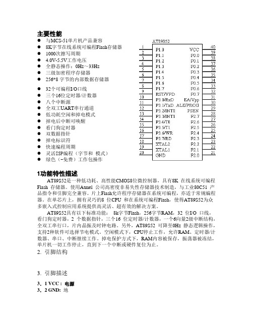
主要性能● 与MCS-51单片机产品兼容● 8K字节在线系统可编程Flash存储器● 1000次擦写周期● 4.0V-5.5V工作电压● 全静态操作:0Hz~33Hz● 三级加密程序存储器● 256*8字节的内部数据存储器● 32个可编程I/O口线● 三个16位定时器/计数器● 八个中断源● 全双工UART串行通道● 低功耗空闲和掉电模式● 掉电后中断可唤醒● 看门狗定时器● 双数据指针● 掉电标识符● 快速编程周期● 灵活ISP编程(字节和模式)● 绿色(-免费)工作包操作1功能特性描述AT89S52是一种低功耗、高性能CMOS8位微控制器,具有8K 在线系统可编程Flash 存储器。
使用Atmel 公司高密度非易失性存储器技术制造,与工业80C51 产品指令和引脚完全兼容。
片上Flash允许程序存储器在系统可编程,亦适于常规编程器。
在单芯片上,拥有灵巧的8 位CPU 和在系统可编程Flash,使得AT89S52为众多嵌入式控制应用系统提供高灵活、超有效的解决方案。
AT89S52具有以下标准功能:8k字节Flash,256字节RAM,32 位I/O 口线,看门狗定时器,2 个数据指针,三个16 位定时器/计数器,一个6向量2级中断结构,全双工串行口,片内晶振及时钟电路。
另外,AT89S52 可降至0Hz 静态逻辑操作,支持2种软件可选择节电模式。
空闲模式下,CPU停止工作,允许RAM、定时器/计数器、串口、中断继续工作。
掉电保护方式下,RAM内容被保存,振荡器被冻结,单片机一切工作停止,直到下一个中断或硬件复位为止。
2. 引脚结构3. 引脚描述3.1 VCC : 电源3.2 GND: 地3.3 P0 口:P0口是一个8位漏极开路的双向I/O口。
作为输出口,每位能驱动8个TTL 逻辑电平。
对P0端口写“1”时,引脚用作高阻抗输入。
当访问外部程序和数据存储器时,P0口也被作为低8位地址/数据复用。
单片机AT89S52介绍
AT89S52简介AT89S52是一个8位单片机,片内ROM全部采用FLASH ROM技术,与MCS-51系列完全兼容,它能以3V的超低电压工作,晶振时钟最高可达24MHz。
AT89S52是标准的40引脚双列直插式集成电路芯片,有4个八位的并行双向I/O端口,分别记作P0、P1、P2、P3。
第31引脚需要接高电位使单片机选用内部程序存储器;第9引脚是复位引脚,要接一个上电手动复位电路;第40脚为电源端VCC,接+5V电源,第20引脚为接地端VSS,通常在VCC和VSS引脚之间接0.1μF高频滤波电容。
第18、19脚之间接上一个12MHz的晶振为单片机提供时钟信号。
AT89S52单片机说明如下:此芯片是一种高性能低功耗的采用CMOS工艺制造的8位微控制器,它提供下列标准特征:8K字节的程序存储器,256字节的RAM,32条I/O线,2个16位定时器/计数器, 一个5中断源两个优先级的中断结构,一个双工的串行口, 片上震荡器和时钟电路。
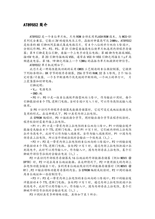
引脚说明::电源电压·VCC·GND:地·P0口:P0口是一组8位漏极开路型双向I/O口,作为输出口用时,每个引脚能驱动8个TTL逻辑门电路。
当对0端口写入1时,可以作为高阻抗输入端使用。
当P0口访问外部程序存储器或数据存储器时,它还可设定成地址数据总线复用的形式。
在这种模式下,P0口具有内部上拉电阻。
在EPROM编程时,P0口接收指令字节,同时输出指令字节在程序校验时。
程序校验时需要外接上拉电阻。
·P1口:P1口是一带有内部上拉电阻的8位双向I/O口。
P1口的输出缓冲能接受或输出4个TTL逻辑门电路。
当对P1口写1时,它们被内部的上拉电阻拉升为高电平,此时可以作为输入端使用。
当作为输入端使用时,P1口因为内)。
部存在上拉电阻,所以当外部被拉低时会输出一个低电流(IIL·P2口:P2是一带有内部上拉电阻的8位双向的I/O端口。
AT89S52资料

•Compatible with MCS-51® Products•8K Bytes of In-System Programmable (ISP) Flash Memory–Endurance: 1000 Write/Erase Cycles• 4.0V to 5.5V Operating Range•Fully Static Operation: 0 Hz to 33 MHz•Three-level Program Memory Lock•256 x 8-bit Internal RAM•32 Programmable I/O Lines•Three 16-bit Timer/Counters•Eight Interrupt Sources•Full Duplex UART Serial Channel•Low-power Idle and Power-down Modes•Interrupt Recovery from Power-down Mode•Watchdog Timer•Dual Data Pointer•Power-off FlagDescriptionThe AT89S52 is a low-power, high-performance CMOS 8-bit microcontroller with 8K bytes of in-system programmable Flash memory. The device is manufactured using Atmel’s high-density nonvolatile memory technology and is compatible with the indus-try-standard 80C51 instruction set and pinout. The on-chip Flash allows the program memory to be reprogrammed in-system or by a conventional nonvolatile memory pro-grammer. By combining a versatile 8-bit CPU with in-system programmable Flash on a monolithic chip, the Atmel AT89S52 is a powerful microcontroller which provides a highly-flexible and cost-effective solution to many embedded control applications. The AT89S52 provides the following standard features: 8K bytes of Flash, 256 bytes of RAM, 32 I/O lines, Watchdog timer, two data pointers, three 16-bit timer/counters, a six-vector two-level interrupt architecture, a full duplex serial port, on-chip oscillator, and clock circuitry. In addition, the AT89S52 is designed with static logic for operation down to zero frequency and supports two software selectable power saving modes. The Idle Mode stops the CPU while allowing the RAM, timer/counters, serial port, and interrupt system to continue functioning. The Power-down mode saves the RAM con-tents but freezes the oscillator, disabling all other chip functions until the next interruptor hardware reset.TQFPPLCCPin ConfigurationsPDIPAT89S52 Block DiagramPin DescriptionVCCSupply voltage.GNDGround.Port 0Port 0 is an 8-bit open drain bidirectional I/O port. As an output port, each pin can sink eight TTL inputs. When 1s are written to port 0 pins, the pins can be used as high-impedance inputs.Port 0 can also be configured to be the multiplexed low-order address/data bus during accesses to external program and data memory. In this mode, P0 has internal pullups.Port 0 also receives the code bytes during Flash program-ming and outputs the code bytes during program verifica-tion. External pullups are required during program verification.Port 1Port 1 is an 8-bit bidirectional I/O port with internal pullups. The Port 1 output buffers can sink/source four TTL inputs. When 1s are written to Port 1 pins, they are pulled high by the internal pullups and can be used as inputs. As inputs, Port 1 pins that are externally being pulled low will source current (I IL) because of the internal pullups.In addition, P1.0 and P1.1 can be configured to be the timer/counter 2 external count input (P1.0/T2) and the timer/counter 2 trigger input (P1.1/T2EX), respectively, as shown in the following table.Port 1 also receives the low-order address bytes during Flash programming and verification.Port 2Port 2 is an 8-bit bidirectional I/O port with internal pullups. The Port 2 output buffers can sink/source four TTL inputs. When 1s are written to Port 2 pins, they are pulled high by the internal pullups and can be used as inputs. As inputs, Port 2 pins that are externally being pulled low will source current (I IL) because of the internal pullups.Port 2 emits the high-order address byte during fetches from external program memory and during accesses to external data memory that use 16-bit addresses (MOVX @ DPTR). In this application, Port 2 uses strong internal pull-ups when emitting 1s. During accesses to external data memory that use 8-bit addresses (MOVX @ RI), Port 2 emits the contents of the P2 Special Function Register. Port 2 also receives the high-order address bits and some control signals during Flash programming and verification. Port 3Port 3 is an 8-bit bidirectional I/O port with internal pullups. The Port 3 output buffers can sink/source four TTL inputs. When 1s are written to Port 3 pins, they are pulled high by the internal pullups and can be used as inputs. As inputs, Port 3 pins that are externally being pulled low will source current (I IL) because of the pullups.Port 3 also serves the functions of various special features of the AT89S52, as shown in the following table.Port 3 also receives some control signals for Flash pro-gramming and verification.RSTReset input. A high on this pin for two machine cycles while the oscillator is running resets the device. This pin drives High for 96 oscillator periods after the Watchdog times out. The DISRTO bit in SFR AUXR (address 8EH) can be used to disable this feature. In the default state of bit DISRTO, the RESET HIGH out feature is enabled.ALE/PROGAddress Latch Enable (ALE) is an output pulse for latching the low byte of the address during accesses to external memory. This pin is also the program pulse input (PROG) during Flash programming.In normal operation, ALE is emitted at a constant rate of 1/6the oscillator frequency and may be used for external timing or clocking purposes. Note, however, that one ALE pulse is skipped during each access to external data memory.If desired, ALE operation can be disabled by setting bit 0 of SFR location 8EH. With the bit set, ALE is active only dur-ing a MOVX or MOVC instruction. Otherwise, the pin isPort Pin Alternate FunctionsP1.0T2 (external count input to Timer/Counter 2),clock-outP1.1T2EX (Timer/Counter 2 capture/reload triggerand direction control)P1.5MOSI (used for In-System Programming)P1.6MISO (used for In-System Programming)P1.7SCK (used for In-System Programming)Port Pin Alternate FunctionsP3.0RXD (serial input port)P3.1TXD (serial output port)P3.2INT0 (external interrupt 0)P3.3INT1 (external interrupt 1)P3.4T0 (timer 0 external input)P3.5T1 (timer 1 external input)P3.6WR (external data memory write strobe) P3.7RD (external data memory read strobe)AT89S52 weakly pulled high. Setting the ALE-disable bit has noeffect if the microcontroller is in external execution mode. PSENProgram Store Enable (PSEN) is the read strobe to exter-nal program memory.When the AT89S52 is executing code from external pro-cycle, except that two PSEN activations are skipped during each access to external data memory.EA/VPPExternal Access Enable. EA must be strapped to GND in order to enable the device to fetch code from external pro-gram memory locations starting at 0000H up to FFFFH.internally latched on reset.EA should be strapped to V CC for internal program execu-tions.This pin also receives the 12-volt programming enable volt-age (V PP) during Flash programming.XTAL1Input to the inverting oscillator amplifier and input to the internal clock operating circuit.XTAL2Output from the inverting oscillator amplifier.Table 1. AT89S52 SFR Map and Reset Values0F8H0FFH0F0HB000000000F7H0E8H0EFH0E0HACC000000000E7H0D8H0DFH0D0HPSW000000000D7H0C8HT2CON00000000T2MODXXXXXX00RCAP2L00000000RCAP2H00000000TL200000000TH2000000000CFH0C0H0C7H0B8HIPXX0000000BFH0B0HP3111111110B7H0A8HIE0X0000000AFH0A0HP211111111AUXR1XXXXXXX0WDTRSTXXXXXXXX0A7H98HSCON00000000SBUFXXXXXXXX9FH90HP11111111197H88HTCON00000000TMOD00000000TL000000000TL100000000TH000000000TH100000000AUXRXXX00XX08FH80HP011111111SP00000111DP0L00000000DP0H00000000DP1L00000000DP1H00000000PCON0XXX000087HSpecial Function RegistersA map of the on-chip memory area called the Special Func-tion Register (SFR) space is shown in Table 1.Note that not all of the addresses are occupied, and unoc-cupied addresses may not be implemented on the chip. Read accesses to these addresses will in general return random data, and write accesses will have an indetermi-nate effect.User software should not write 1s to these unlisted loca-tions, since they may be used in future products to invoke new features. In that case, the reset or inactive values of the new bits will always be 0.Timer 2 Registers: Control and status bits are contained in registers T2CON (shown in Table 2) and T2MOD (shown in Table 3) for Timer 2. The register pair (RCAP2H, RCAP2L) are the Capture/Reload registers for Timer 2 in 16-bit cap-ture mode or 16-bit auto-reload mode.Interrupt Registers: The individual interrupt enable bits are in the IE register. Two priorities can be set for each of the six interrupt sources in the IP register.Table 2. T2CON – Timer/Counter 2 Control RegisterT2CON Address = 0C8H Reset Value = 0000 0000BBit AddressableBit TF2EXF2RCLK TCLK EXEN2TR2C/T2CP/RL276543210Symbol FunctionTF2Timer 2 overflow flag set by a Timer 2 overflow and must be cleared by software. TF2 will not be set when either RCLK = 1 or TCLK = 1.EXF2Timer 2 external flag set when either a capture or reload is caused by a negative transition on T2EX and EXEN2 = 1.When Timer 2 interrupt is enabled, EXF2 = 1 will cause the CPU to vector to the Timer 2 interrupt routine. EXF2 must becleared by software. EXF2 does not cause an interrupt in up/down counter mode (DCEN = 1).RCLK Receive clock enable. When set, causes the serial port to use Timer 2 overflow pulses for its receive clock in serial port Modes 1 and 3. RCLK = 0 causes Timer 1 overflow to be used for the receive clock.TCLK Transmit clock enable. When set, causes the serial port to use Timer 2 overflow pulses for its transmit clock in serial port Modes 1 and 3. TCLK = 0 causes Timer 1 overflows to be used for the transmit clock.EXEN2Timer 2 external enable. When set, allows a capture or reload to occur as a result of a negative transition on T2EX if Timer2 is not being used to clock the serial port. EXEN2 = 0 causes Timer 2 to ignore events at T2EX.TR2Start/Stop control for Timer 2. TR2 = 1 starts the timer.C/T2Timer or counter select for Timer 2. C/T2 = 0 for timer function. C/T2 = 1 for external event counter (falling edge triggered). CP/RL2Capture/Reload select. CP/RL2 = 1 causes captures to occur on negative transitions at T2EX if EXEN2 = 1. CP/RL2 = 0 causes automatic reloads to occur when Timer 2 overflows or negative transitions occur at T2EX when EXEN2 = 1. When either RCLK or TCLK = 1, this bit is ignored and the timer is forced to auto-reload on Timer 2 overflow.AT89S52Dual Data Pointer Registers: To facilitate accessing both internal and external data memory, two banks of 16-bit Data Pointer Registers are provided: DP0 at SFR address locations 82H-83H and DP1 at 84H-85H. Bit DPS = 0 in SFR AUXR1 selects DP0 and DPS = 1 selects DP1. The user should always initialize the DPS bit to the appropriate value before accessing the respective Data Pointer Register.Power Off Flag: The Power Off Flag (POF) is located at bit 4 (PCON.4) in the PCON SFR. POF is set to “1” during power up. It can be set and rest under software control and is not affected by reset.Table 3a. AUXR: Auxiliary RegisterAUXR Address = 8EH Reset Value = XXX00XX0B Not Bit Addressable–––WDIDLE DISRTO––DISALE Bit76543210–Reserved for future expansionDISALE Disable/Enable ALEDISALE Operating Mode0ALE is emitted at a constant rate of 1/6 the oscillator frequency1ALE is active only during a MOVX or MOVC instructionDISRTO Disable/Enable Reset outDISRTO0Reset pin is driven High after WDT times out1Reset pin is input onlyWDIDLE Disable/Enable WDT in IDLE modeWDIDLE0WDT continues to count in IDLE mode1WDT halts counting in IDLE modeTable 3b. AUXR1: Auxiliary Register 1AUXR1Address = A2H Reset Value = XXXXXXX0B Not Bit Addressable–––––––DPS Bit76543210–Reserved for future expansionDPS Data Pointer Register SelectDPS0Selects DPTR Registers DP0L, DP0H1Selects DPTR Registers DP1L, DP1HMemory OrganizationMCS-51 devices have a separate address space for Pro-gram and Data Memory. Up to 64K bytes each of external Program and Data Memory can be addressed.Program Memorydirected to external memory.On the AT89S52, if EA is connected to V CC, program fetches to addresses 0000H through 1FFFH are directed to internal memory and fetches to addresses 2000H through FFFFH are to external memory.Data MemoryThe AT89S52 implements 256 bytes of on-chip RAM. The upper 128 bytes occupy a parallel address space to the Special Function Registers. This means that the upper 128 bytes have the same addresses as the SFR space but are physically separate from SFR space.When an instruction accesses an internal location above address 7FH, the address mode used in the instruction specifies whether the CPU accesses the upper 128 bytes of RAM or the SFR space. Instructions which use direct addressing access of the SFR space.For example, the following direct addressing instruction accesses the SFR at location 0A0H (which is P2).MOV0A0H,#dataInstructions that use indirect addressing access the upper 128 bytes of RAM. For example, the following indirect addressing instruction, where R0 contains 0A0H, accesses the data byte at address 0A0H, rather than P2 (whose address is 0A0H).MOV@R0,#dataNote that stack operations are examples of indirect addressing, so the upper 128 bytes of data RAM are avail-able as stack space.AT89S52Watchdog Timer(One-time Enabled with Reset-out)The WDT is intended as a recovery method in situations where the CPU may be subjected to software upsets. The WDT consists of a 13-bit counter and the Watchdog Timer Reset (WDTRST) SFR. The WDT is defaulted to disable from exiting reset. To enable the WDT, a user must write 01EH and 0E1H in sequence to the WDTRST register (SFR location 0A6H). When the WDT is enabled, it will increment every machine cycle while the oscillator is run-ning. The WDT timeout period is dependent on the external clock frequency. There is no way to disable the WDT except through reset (either hardware reset or WDT over-flow reset). When WDT overflows, it will drive an output RESET HIGH pulse at the RST pin.Using the WDTTo enable the WDT, a user must write 01EH and 0E1H in sequence to the WDTRST register (SFR location 0A6H). When the WDT is enabled, the user needs to service it by writing 01EH and 0E1H to WDTRST to avoid a WDT over-flow. The 13-bit counter overflows when it reaches 8191 (1FFFH), and this will reset the device. When the WDT is enabled, it will increment every machine cycle while the oscillator is running. This means the user must reset the WDT at least every 8191 machine cycles. To reset the WDT the user must write 01EH and 0E1H to WDTRST. WDTRST is a write-only register. The WDT counter cannot be read or written. When WDT overflows, it will generate an output RESET pulse at the RST pin. The RESET pulse duration is 96xTOSC, where TOSC=1/FOSC. To make the best use of the WDT, it should be serviced in those sec-tions of code that will periodically be executed within the time required to prevent a WDT reset.WDT During Power-down and IdleIn Power-down mode the oscillator stops, which means the WDT also stops. While in Power-down mode, the user does not need to service the WDT. There are two methods of exiting Power-down mode: by a hardware reset or via a level-activated external interrupt which is enabled prior to entering Power-down mode. When Power-down is exited with hardware reset, servicing the WDT should occur as it normally does whenever the AT89S52 is reset. Exiting Power-down with an interrupt is significantly different. The interrupt is held low long enough for the oscillator to stabi-lize. When the interrupt is brought high, the interrupt is serviced. To prevent the WDT from resetting the device while the interrupt pin is held low, the WDT is not started until the interrupt is pulled high. It is suggested that the WDT be reset during the interrupt service for the interrupt used to exit Power-down mode.To ensure that the WDT does not overflow within a few states of exiting Power-down, it is best to reset the WDT just before entering Power-down mode.Before going into the IDLE mode, the WDIDLE bit in SFR AUXR is used to determine whether the WDT continues to count if enabled. The WDT keeps counting during IDLE (WDIDLE bit = 0) as the default state. To prevent the WDT from resetting the AT89S52 while in IDLE mode, the user should always set up a timer that will periodically exit IDLE, service the WDT, and reenter IDLE mode.With WDIDLE bit enabled, the WDT will stop to count in IDLE mode and resumes the count upon exit from IDLE.UARTThe UART in the AT89S52 operates the same way as the UART in the AT89C51 and AT89C52. For further informa-tion on the UART operation, refer to the ATMEL Web site (). From the home page, select ‘Prod-ucts’, then ‘8051-Architecture Flash Microcontroller’, then ‘Product Overview’.Timer 0 and 1Timer 0 and Timer 1 in the AT89S52 operate the same way as Timer 0 and Timer 1 in the AT89C51 and AT89C52. For further information on the timers’ operation, refer to the ATMEL Web site (). From the home page, select ‘Products’, then ‘8051-Architecture Flash Microcontroller’, then ‘Product Overview’.Timer 2Timer 2 is a 16-bit Timer/Counter that can operate as either a timer or an event counter. The type of operation is Timer 2 has three operating modes: capture, auto-reload (up or down counting), and baud rate generator. The modes are selected by bits in T2CON, as shown in Table 3. Timer 2 consists of two 8-bit registers, TH2 and TL2. In the Timer function, the TL2 register is incremented every machine cycle. Since a machine cycle consists of 12 oscil-lator periods, the count rate is 1/12 of the oscillator frequency.Table 3. Timer 2 Operating ModesRCLK +TCLK CP/RL2TR2MODE00116-bit Auto-reload01116-bit Capture1X1Baud Rate GeneratorX X0(Off)In the Counter function, the register is incremented in response to a 1-to-0 transition at its corresponding external input pin, T2. In this function, the external input is sampled during S5P2 of every machine cycle. When the samples show a high in one cycle and a low in the next cycle, the count is incremented. The new count value appears in the register during S3P1 of the cycle following the one in which the transition was detected. Since two machine cycles (24 oscillator periods) are required to recognize a 1-to-0 transi-tion, the maximum count rate is 1/24 of the oscillator fre-quency. To ensure that a given level is sampled at least once before it changes, the level should be held for at least one full machine cycle.Capture ModeIn the capture mode, two options are selected by bit EXEN2 in T2CON. If EXEN2 = 0, Timer 2 is a 16-bit timer or counter which upon overflow sets bit TF2 in T2CON.This bit can then be used to generate an interrupt. If EXEN2 = 1, Timer 2 performs the same operation, but a 1-to-0 transition at external input T2EX also causes the current value in TH2 and TL2 to be captured into RCAP2H and RCAP2L, respectively. In addition, the transition at T2EX causes bit EXF2 in T2CON to be set. The EXF2 bit, like TF2, can generate an interrupt. The capture mode is illustrated in Figure 5.Auto-reload (Up or Down Counter)Timer 2 can be programmed to count up or down when configured in its 16-bit auto-reload mode. This feature is invoked by the DCEN (Down Counter Enable) bit located in the SFR T2MOD (see Table 4). Upon reset, the DCEN bit is set to 0 so that timer 2 will default to count up. When DCEN is set, Timer 2 can count up or down, depending on the value of the T2EX pin.Figure 5. Timer in Capture ModeFigure 6 shows Timer 2 automatically counting up when DCEN=0. In this mode, two options are selected by bit EXEN2 in T2CON. If EXEN2 = 0, Timer 2 counts up to 0FFFFH and then sets the TF2 bit upon overflow. The overflow also causes the timer registers to be reloaded with the 16-bit value in RCAP2H and RCAP2L. The values in Timer in Capture ModeRCAP2H and RCAP2L are preset by software. If EXEN2 = 1, a 16-bit reload can be triggered either by an overflow or by a 1-to-0 transition at external input T2EX. This transition also sets the EXF2 bit. Both the TF2 and EXF2 bits can generate an interrupt if enabled. Setting the DCEN bit enables Timer 2 to count up or down, as shown in Figure 6. In this mode, the T2EX pin controls the direction of the count. A logic 1 at T2EX makes Timer 2 count up. The timer will overflow at 0FFFFH and set the TF2 bit. This overflow also causes the 16-bit value in RCAP2H and RCAP2L to be reloaded into the timer regis-ters, TH2 and TL2, respectively.A logic 0 at T2EX makes Timer 2 count down. The timer underflows when TH2 and TL2 equal the values stored in RCAP2H and RCAP2L. The underflow sets the TF2 bit and causes 0FFFFH to be reloaded into the timer registers. The EXF2 bit toggles whenever Timer 2 overflows or underflows and can be used as a 17th bit of resolution. In this operating mode, EXF2 does not flag an interrupt.AT89S52 Figure 6. Timer 2 Auto Reload Mode (DCEN = 0)Table 4. T2MOD – Timer 2 Mode Control RegisterT2MOD Address = 0C9H Reset Value = XXXX XX00B Not Bit Addressable––––––T2OE DCEN Bit76543210Symbol Function–Not implemented, reserved for futureT2OE Timer 2 Output Enable bitDCEN When set, this bit allows Timer 2 to be configured as an up/down counterFigure 7. Timer 2 Auto Reload Mode (DCEN = 1)Figure 8. Timer 2 in Baud Rate Generator ModeAT89S52Baud Rate GeneratorTimer 2 is selected as the baud rate generator by setting TCLK and/or RCLK in T2CON (Table 2). Note that the baud rates for transmit and receive can be different if Timer 2 is used for the receiver or transmitter and Timer 1 is used for the other function. Setting RCLK and/or TCLK puts Timer 2 into its baud rate generator mode, as shown in Fig-ure 8.The baud rate generator mode is similar to the auto-reload mode, in that a rollover in TH2 causes the Timer 2 registers to be reloaded with the 16-bit value in registers RCAP2H and RCAP2L, which are preset by software.The baud rates in Modes 1 and 3 are determined by Timer 2’s overflow rate according to the following equation.The Timer can be configured for either timer or counteroperation. In most applications, it is configured for timer Timer 2 when it is used as a baud rate generator. Normally,as a timer, it increments every machine cycle (at 1/12 the oscillator frequency). As a baud rate generator, however, itincrements every state time (at 1/2 the oscillator fre-quency). The baud rate formula is given below.where (RCAP2H, RCAP2L) is the content of RCAP2H and RCAP2L taken as a 16-bit unsigned integer.Timer 2 as a baud rate generator is shown in Figure 8. This figure is valid only if RCLK or TCLK = 1 in T2CON. Note that a rollover in TH2 does not set TF2 and will not gener-ate an interrupt. Note too, that if EXEN2 is set, a 1-to-0transition in T2EX will set EXF2 but will not cause a reload from (RCAP2H, RCAP2L) to (TH2, TL2). Thus, when Timer 2 is in use as a baud rate generator, T2EX can be used as an extra external interrupt.Note that when Timer 2 is running (TR2 = 1) as a timer in the baud rate generator mode, TH2 or TL2 should not be read from or written to. Under these conditions, the Timer is incremented every state time, and the results of a read or write may not be accurate. The RCAP2 registers may be read but should not be written to, because a write might overlap a reload and cause write and/or reload errors. The timer should be turned off (clear TR2) before accessing the Timer 2 or RCAP2 registers.Figure 9. Timer 2 in Clock-Out ModeModes 1 and 3 Baud Rates Timer 2 Overflow Rate16-----------------------------------------------------------=Modes 1 and 3Baud Rate ---------------------------------------Oscillator Frequency 32 x [65536-RCAP2H,RCAP2L)]-------------------------------------------------------------------------------------=Programmable Clock OutA 50% duty cycle clock can be programmed to come out on P1.0, as shown in Figure 9. This pin, besides being a regu-lar I/O pin, has two alternate functions. It can be pro-grammed to input the external clock for Timer/Counter 2 or to output a 50% duty cycle clock ranging from 61 Hz to 4MHz at a 16 MHz operating frequency.To configure the Timer/Counter 2 as a clock generator, bit must be set. Bit TR2 (T2CON.2) starts and stops the timer.The clock-out frequency depends on the oscillator fre-quency and the reload value of Timer 2 capture registers (RCAP2H, RCAP2L), as shown in the following equation.In the clock-out mode, Timer 2 roll-overs will not generate an interrupt. This behavior is similar to when Timer 2 is used as a baud-rate generator. It is possible to use Timer 2as a baud-rate generator and a clock generator simulta-neously. Note, however, that the baud-rate and clock-out frequencies cannot be determined independently from one another since they both use RCAP2H and RCAP2L.InterruptsThe AT89S52 has a total of six interrupt vectors: two exter-ers 0, 1, and 2), and the serial port interrupt. These interrupts are all shown in Figure 10.Each of these interrupt sources can be individually enabled or disabled by setting or clearing a bit in Special Function Register IE. IE also contains a global disable bit, EA, which disables all interrupts at once.Note that Table 5 shows that bit position IE.6 is unimple-mented. In the AT89S52, bit position IE.5 is also unimple-mented. User software should not write 1s to these bit positions, since they may be used in future AT89 products.Timer 2 interrupt is generated by the logical OR of bits TF2and EXF2 in register T2CON. Neither of these flags is cleared by hardware when the service routine is vectored to. In fact, the service routine may have to determine whether it was TF2 or EXF2 that generated the interrupt,and that bit will have to be cleared in software.The Timer 0 and Timer 1 flags, TF0 and TF1, are set at S5P2 of the cycle in which the timers overflow. The values are then polled by the circuitry in the next cycle. However,the Timer 2 flag, TF2, is set at S2P2 and is polled in the same cycle in which the timer overflows.Table 5. Interrupt Enable (IE) RegisterFigure 10. Interrupt SourcesClock-Out Frequency Oscillator Frequency4 x [65536-(RCAP2H,RCAP2L)]------------------------------------------------------------------------------------= (MSB) (LSB)EA–ET2ESET1EX1ET0EX0Enable Bit = 1 enables the interrupt. Enable Bit = 0 disables the interrupt.Symbol Position FunctionEAIE.7Disables all interrupts. If EA =0, no interrupt is acknowledged. If EA = 1, each interrupt source is individually enabled or disabled by setting or clearing its enable bit.–IE.6Reserved.ET2IE.5Timer 2 interrupt enable bit.ES IE.4Serial Port interrupt enable bit.ET1IE.3Timer 1 interrupt enable bit.EX1IE.2External interrupt 1 enable bit.ET0IE.1Timer 0 interrupt enable bit.EX0IE.0External interrupt 0 enable bit.User software should never write 1s to unimplemented bits, because they may be used in future AT89 products.AT89S52Oscillator CharacteristicsXTAL1 and XTAL2 are the input and output, respectively, of an inverting amplifier that can be configured for use as an on-chip oscillator, as shown in Figure 11. Either a quartz crystal or ceramic resonator may be used. To drive the device from an external clock source, XTAL2 should be left unconnected while XTAL1 is driven, as shown in Figure 12. There are no requirements on the duty cycle of the external clock signal, since the input to the internal clocking circuitry is through a divide-by-two flip-flop, but minimum and maxi-mum voltage high and low time specifications must be observed.Idle ModeIn idle mode, the CPU puts itself to sleep while all the on-chip peripherals remain active. The mode is invoked by software. The content of the on-chip RAM and all the spe-cial functions registers remain unchanged during this mode. The idle mode can be terminated by any enabled interrupt or by a hardware reset.Note that when idle mode is terminated by a hardware reset, the device normally resumes program execution from where it left off, up to two machine cycles before the internal reset algorithm takes control. On-chip hardware inhibits access to internal RAM in this event, but access to the port pins is not inhibited. To eliminate the possibility of an unexpected write to a port pin when idle mode is termi-nated by a reset, the instruction following the one that invokes idle mode should not write to a port pin or to exter-nal memory.Power-down ModeIn the Power-down mode, the oscillator is stopped, and the instruction that invokes Power-down is the last instruction executed. The on-chip RAM and Special Function Regis-ters retain their values until the Power-down mode is termi-nated. Exit from Power-down mode can be initiated either by a hardware reset or by an enabled external interrupt. Reset redefines the SFRs but does not change the on-chip RAM. The reset should not be activated before V CC is restored to its normal operating level and must be held active long enough to allow the oscillator to restart and stabilize.Figure 11. Oscillator ConnectionsNote: C1, C2 = 30 pF ± 10 pF for Crystals= 40 pF ± 10 pF for Ceramic Resonators Figure 12. External Clock Drive ConfigurationTable 6. Status of External Pins During Idle and Power-down ModesMode Program Memory ALE PSEN PORT0PORT1PORT2PORT3 Idle Internal11Data Data Data Data Idle External11Float Data Address Data Power-down Internal00Data Data Data Data Power-down External00Float Data Data Data。
单片机原理及应用之AT89S52

单片机原理及应用之AT89S52AT89S52是一款由Atmel公司生产的8位单片机,采用CMOS工艺制造,并且内部集成了丰富的功能模块和外设接口。
它具有较高的性能和良好的稳定性,广泛应用于各种电子设备中。
AT89S52单片机的基本原理是通过控制器对内部资源进行配置和控制,从而实现各种功能。
它的主要构成部分包括中央处理器(CPU),存储器(RAM和ROM),输入/输出接口(IO),定时/计数器(Timer/Counter)和串行通信接口等。
首先,AT89S52单片机的CPU是其心脏部件,它采用基于8051内核的结构,具有8位数据总线和16位地址总线。
CPU负责执行程序指令,以及对数据进行运算和处理。
其次,AT89S52内部集成了包括RAM、ROM和EEPROM等多种存储器。
其中,RAM用于临时存储数据和程序,ROM用于存储程序代码,EEPROM可用于存储非易失性数据。
AT89S52还具有强大的输入/输出接口,用于与外部设备进行通信。
它具有多个I/O引脚,可以用于连接传感器、显示器、键盘等外部设备,并通过程序控制实现数据的输入和输出。
除此之外,AT89S52还内置了多个定时/计数器模块,用于生成精确的时间延迟和计算时间。
这些定时/计数器可以用于测量时间、产生脉冲信号、控制外设设备等。
此外,AT89S52还支持多种串行通信接口,如UART、SPI和I2C等。
这些接口可以与其他设备进行数据传输和通信,实现单片机与外部设备的数据交互。
AT89S52单片机应用广泛。
它既可以作为独立的控制芯片,也可以作为其他数字电路和模拟电路的核心控制部分。
在家电、电子仪器、工业自动化和电子玩具等领域,AT89S52都有着重要的应用。
具体来说,AT89S52可以用于控制家电设备,如洗衣机、空调、微波炉等。
它通过连接传感器和执行器,实现对温度、光照强度等参数的检测和控制。
此外,AT89S52还可以用于仪器设备的控制。
例如,可以将其用作控制面板上的核心处理器,实现对仪器设备的各种参数监测和控制。
AT89S52单片机介绍
AT89S52单片机介绍AT89S52 具有以下标准功能:8k 字节 Flash,256 字节 RAM,32 位 I/O 口线,看门狗定时器,2 个数据指针,三个 16 位定时器/计数器,一个 6 向量 2 级中断结构,全双工串行口,片内晶振及时钟电路。
另外,AT89S52 可降至 0Hz 静态逻辑操作,支持 2 种软件可选择节电模式。
空闲模式下,CPU停止工作,允许 RAM、定时器/计数器、串口、中断继续工作。
掉电保护方式下,RAM 内容被保存,振荡器被冻结,单片机一切工作停止,直到下一个中断或硬件复位为止。
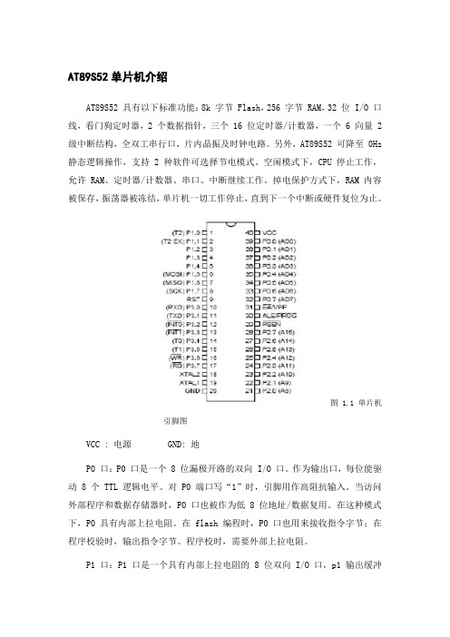
图 1.1 单片机引脚图VCC : 电源 GND: 地P0 口:P0 口是一个 8 位漏极开路的双向 I/O 口。
作为输出口,每位能驱动 8 个 TTL 逻辑电平。
对 P0 端口写“1”时,引脚用作高阻抗输入。
当访问外部程序和数据存储器时,P0 口也被作为低 8 位地址/数据复用。
在这种模式下,P0 具有内部上拉电阻。
在 flash 编程时,P0 口也用来接收指令字节;在程序校验时,输出指令字节。
程序校时,需要外部上拉电阻。
P1 口:P1 口是一个具有内部上拉电阻的 8 位双向 I/O 口,p1 输出缓冲器能驱动 4 个TTL 逻辑电平。
对 P1 端口写“1”时,内部上拉电阻把端口拉高,此时可以作为输入口使用。
作为输入使用时,被外部拉低的引脚由于内部电阻的原因,将输出电流(IIL)。
此外,P1.0 和 P1.2 分别作定时器/计数器 2 的外部计数输入(P1.0/T2)和时器/计数器 2的触发输入(P1.1/T2EX),具体如下表所示。
表1.1 AT89S52 P1口第二功能表P2 口:P2 口是一个具有内部上拉电阻的 8 位双向 I/O 口,P2 输出缓冲器能驱动 4 个TTL 逻辑电平。
对 P2 端口写“1”时,内部上拉电阻把端口拉高,此时可以作为输入口使用。
作为输入使用时,被外部拉低的引脚由于内部电阻的原因,将输出电流(IIL)在访问外部程序存储器或用 16 位地址读取外部数据存储器(例如执行 MOVX @DPTR)时,P2 口送出高八位地址P3 口:P3 口是一个具有内部上拉电阻的 8 位双向 I/O 口,p2 输出缓冲器能驱动 4 个TTL 逻辑电平。
AT89S52芯片详细介绍
上集成了中央处理单元CPU、随机存储器RAM、只读存储器ROM、定时器/计数器和多种输入/输出(I/O),如并行I/O、串行I/O和A/D转换器等。
就其组成而言一块单片机就是一台计算机。
典型的结构如图1-1所示。
由于它具有许多适用于控制的指令和硬件支持而广泛应用于工业控制、仪器仪表、外设控制、顺序控制器中,所以又称为微控制单元(MCU)。
MCS-51系列单片机,是Intel公司继MCS-48系列单片机之后,在1980年推出的高档8位单片机。
当时MCS-51系列产品有8051、8031、8751、80C51、80C31等型号。
它们的结构基本相同,其主要差别反映在寄存器的配置上有所不同。
8051内部没有4K字节的掩膜ROM程序存储器,8031片内没有程序存储器,而8751是将8051片内的ROM换成EPROM。
ATMEL89系列单片机是ATMEL公司的以8031核构成的8位Flash单片机系列。
这个系列单片机的最大特点就是在片内含有Flash存储器,AT89S52单片机是一种低功耗高性能的CMOS8位微控制器,内置8KB可在线编程闪存。
该器件采用Atmel 公司的高密度非易失性存储技术生产,其指令与工业标准的80C51指令集兼容。
片内程序存储器允许重复在线编程,允许程序存储器在系统内通过SPI串行口改写或用同用的非易失性存储器改写。
通过把通用的8位CPU与可在线下载的Flash集成在一个芯片上,AT89S52便成为一个高效的微型计算机。
它的应用范围广,可用于解决复杂的控制问题,且成本较低。
其结构框图如图1-2所示。
1.2 特性AT89S52的主要特性如下:兼容MCS51产品8K字节可擦写1000次的在线可编程ISP 闪存4.0V到5.5V的工作电源范围全静态工作:0Hz ~24MHz3级程序存储器加密256字节内部RAM32条可编程I/O线3个16位定时器/计数器8个中断源UART串行通道低功耗空闲方式和掉电方式通过中断终止掉电方式看门狗定时器双数据指针灵活的在线编程(字节和页模式)1.3 引脚功能与封装按照功能,AT89S52的引脚可分为主电源、外接晶体振荡或振荡器、多功能I/O口、控制和复位等。
AT89S52说明书
主要性能● 与MCS-51 单片机产品兼容● 8K 字节在系统可编程Flash 存储器● 1000 次擦写周期● 全静态操作:0Hz~33Hz● 三级加密程序存储器● 32 个可编程I/O 口线● 三个16 位定时器/计数器● 八个中断源● 全双工UART 串行通道● 低功耗空闲和掉电模式● 掉电后中断可唤醒AT89S528位微控制器R● 看门狗定时器● 双数据指针● 掉电标识符功能特性描述AT89S52 是一种低功耗、高性能CMOS8 位微控制器,具有8K 在系统可编程Flash 存储器。
使用Atmel 公司高密度非易失性存储器技术制造,与工业80C51 产品指令和引脚完全兼容。
片上Flash 允许程序存储器在系统可编程,亦适于常规编程器。
在单芯片上,拥有灵巧的8 位CPU 和在系统可编程Flash,使得AT89S52 为众多嵌入式控制应用系统提供高灵活、超有效的解决方案。
AT89S52 具有以下标准功能:8k 字节Flash,256 字节RAM,32 位I/O 口线,看门狗定时器,2 个数据指针,三个16 位定时器/计数器,一个 6 向量 2 级中断结构,全双工串行口,片内晶振及时钟电路。
另外,AT89S52 可降至0Hz 静态逻辑操作,支持2 种软件可选择节电模式。
空闲模式下,CPU 停止工作,允许RAM、定时器/计数器、串口、中断继续工作。
掉电保护方式下,RAM 内容被保存,振荡器被冻结,单片机一切工作停止,直到下一个中断或硬件复位为止。
8K字节在系统可编程FlashAT89S52Rev. 1919-07/011AT89S52 引脚结构2AT89S52 方框图引脚功能描述3VCC :电源GND:地AT89S52P0口:P0 口是一个8 位漏极开路的双向I/O 口。
作为输出口,每位能驱动8 个TTL 逻辑电平。
对P0 端口写“1”时,引脚用作高阻抗输入。
当访问外部程序和数据存储器时,P0 口也被作为低8 位地址/数据复用。
单片机AT89S52中文资料
单⽚机AT89S52中⽂资料单⽚机AT89S52中⽂资料AT89S521主要性能l 与MCS-51单⽚机产品兼容l 8K字节在系统可编程Flash存储器l 1000次擦写周期l 全静态操作:0Hz~33MHzl 三级加密程序存储器l 32个可编程I/O⼝线l 三个16位定时器/计数器l ⼋个中断源l 全双⼯UART串⾏通道l 低功耗空闲和掉电模式l 掉电后中断可唤醒l 看门狗定时器l 双数据指针l 掉电标识符功能特性描述AT89S52是⼀种低功耗、⾼性能CMOS8位微控制器,具有8K 在系统可编程Flash 存储器。
使⽤Atmel 公司⾼密度⾮易失性存储器技术制造,与⼯业80C51 产品指令和引脚完全兼容。
⽚上Flash允许程序存储器在系统可编程,亦适于常规编程器。
在单芯⽚上,拥有灵巧的8 位CPU 和在系统可编程Flash,使得AT89S52为众多嵌⼊式控制应⽤系统提供⾼灵活、超有效的解决⽅案。
AT89S52具有以下标准功能: 8k字节Flash,256字节RAM,32 位I/O ⼝线,看门狗定时器,2 个数据指针,三个16 位定时器/计数器,⼀个6向量2级中断结构,全双⼯串⾏⼝,⽚内晶振及时钟电路。
另外,AT89S52 可降⾄0Hz 静态逻辑操作,⽀持2种软件可选择节电模式。
空闲模式下,CPU停⽌⼯作,允许RAM、定时器/计数器、串⼝、中断继续⼯作。
掉电保护⽅式下,RAM内容被保存,振荡器被冻结,单⽚机⼀切⼯作停⽌,直到下⼀个中断或硬件复位为⽌。
R8 位微控制器8K 字节在系统可编程FlashAT89S52Rev. 1919-07/01AT89S522 引脚结构AT89S523 ⽅框图引脚功能描述AT89S524 VCC : 电源GND: 地P0 ⼝:P0⼝是⼀个8位漏极开路的双向I/O⼝。
作为输出⼝,每位能驱动8个TTL逻辑电平。
对P0端⼝写“1”时,引脚⽤作⾼阻抗输⼊。
当访问外部程序和数据存储器时,P0⼝也被作为低8位地址/数据复⽤。
AT89S52芯片资料的文献翻译
AT89S52芯片资料主要性能l 与MCS-51单片机产品兼容l 8K字节在系统可编程Flash存储器l 1000次擦写周期l 全静态操作:0Hz~33Hzl 三级加密程序存储器l 32个可编程I/O口线l 三个16位定时器/计数器l 八个中断源l 全双工UART串行通道l 低功耗空闲和掉电模式l 掉电后中断可唤醒l 看门狗定时器l 双数据指针l 掉电标识符功能特性描述AT89S52是一种低功耗、高性能CMOS8位微控制器,具有8K 在系统可编程Flash 存储器。
使用Atmel 公司高密度非易失性存储器技术制造,与工业80C51 产品指令和引脚完全兼容。
片上Flash允许程序存储器在系统可编程,亦适于常规编程器。
在单芯片上,拥有灵巧的8 位CPU 和在系统可编程Flash,使得AT89S52为众多嵌入式控制应用系统提供高灵活、超有效的解决方案。
AT89S52具有以下标准功能:8k字节Flash,256字节RAM,32 位I/O 口线,看门狗定时器,2 个数据指针,三个16 位定时器/计数器,一个6向量2级中断结构,全双工串行口,片内晶振及时钟电路。
另外,AT89S52 可降至0Hz 静态逻辑操作,支持2种软件可选择节电模式。
空闲模式下,CPU停止工作,允许RAM、定时器/计数器、串口、中断继续工作。
掉电保护方式下,RAM内容被保存,振荡器被冻结,单片机一切工作停止,直到下一个中断或硬件复位为止。
储器结构MCS-51器件有单独的程序存储器和数据存储器。
外部程序存储器和数据存储器都可以64K 寻址。
程序存储器:如果EA引脚接地,程序读取只从外部存储器开始。
对于 89S52,如果EA 接VCC,程序读写先从内部存储器(地址为0000H~1FFFH)开始,接着从外部寻址,寻址地址为:2000H~FFFFH。
数据存储器:AT89S52 有256 字节片内数据存储器。
高128 字节与特殊功能寄存器重叠。
也就是说高128字节与特殊功能寄存器有相同的地址,而物理上是分开的。