NEXON压力传感器选型手册
如何选用压力传感器_1

如何选用压力传感器低压硅传感器,可以对非常之一磅/in2的应力产生响应,目前已有这种产品的生产和应用。
在特别小的变化范围内,硅传感器已能测量液位压力的微弱变化或呼出物施加的压力。
这些装置采纳了压力感测的新型技术,可以取代许多应用的机械压力装置。
但你如何能在应用中进行最好的选择呢?推断的好方法就是测试硅传感器和传统传感器间的差别,市场优势和你所用的硅传感器的技术规格。
什么能正确的组成低压传感器系统?一般来说,在硅传感器中典型的压力范围在00.15psiF.S.之间,经常能到上升到010,000psi。
厂商对不同低压的定义为,基于其传感器的设计和它们的生产过程。
响应小于5psi的传感器一般要求不同的冲模拓扑和工艺技术。
依据此问题的争论,也就是将小于5psi的压力定义为低压范围。
硅工艺的差异形成低压感测的硅微机械元件由同类工艺制造,以形成标准的压力气程元件,但存在关键的区分。
标准量程的元件包括蚀刻在薄隔膜上的电阻桥(惠斯通方式)。
当电压源激励的压力形成隔膜偏移时就会转变电阻值并且引起输出电压的变化。
低压硅传感器工作与此类似,但也存在明显的特征,包括突起的隔膜结构和用于应力集中的约50%的隔膜面积。
精确地蚀薄情膜厚度和策略的放置电阻也能极大地扩大传感器的容量。
另外,硅传感器采纳传统的半导体批处理工艺也会消失其规模生产的成本优势。
低压硅传感器通常用于以下三个主要市场:1.HVAC.低压传感器是加热、通风和空调系统中不行缺少的部件。
在其它应用中,它们可以监测通风和空气流量,确定气流的体积,检测由于弄脏的过滤器变化引起的负荷问题以及掌握整个系统的压力。
这些应用都要求产品在0.015psi的压力变化中能检测出压力差别。
2.医药,假如没有小尺寸的传感器,很多医学应用都不行能检测环境变化和条件。
所以设计必需满意如下要求:相对小的传感器(12mm),能测量人体内的流体压力。
这些装置一般为导尿管器件,它们可以插入头盖骨。
维亚特兰压力传感器选型指南说明书

Viatran Phone: 1‐716‐629‐38003829 Forest Parkway Fax: 1‐716‐693‐9162_______________White PaperGuide to Pressure Transducer SelectionMost applications for pressure transducers are relatively straightforward. Install the transducer according to manufacturer’s recommendations, and obtain an accurate reading from an exceptionally reliable device. But life does not always follow the straight and narrow path. The purpose of this article is to provide some guidelines for helping a transducer user detect atypical conditions and compensate for them through the proper selection and application of the transducer.Why Use a Transducer?Pressure transducers are used to generate an electrical output for a variety of uses that may include computerized data collection, process monitoring and control, or electronic transmission of a pressure reading to a remote display. Another reason for using transducers is their accuracy. Transducers provide accuracies ranging from 0.1 percent full scale, with a typical accuracy of 0.5 percent.The greater the accuracy required, the more expensive the pressure measuring device. But since product quality in many processes is directly related to how accurately the pressure is maintained, the expense of a more accurate device will quickly be justified.Dealing with Abnormal ConditionsOnce the need for a pressure transducer has been determined, it is prudent to determine if there might be some out of the ordinary conditions that could upset transducer performance. The balance of this article will identify some of these conditions and what can be done to compensate for them.Temperature DynamicsTwo sources of temperature variation can affect transducer performance-ambient conditions and the fluid medium itself. Ambient conditions include such things as abrupt changes in air temperature due to heating and cooling systems cycling on and off and the effects of radiant energy impinging on the transducer. Variations in the fluid temperature occur most often during start-up of a process as the fluid goes from room temperature to a higher operating temperature.Dynamic temperature problems may arise because pressure transducers are calibrated under static conditions of both pressure and temperature. Dynamic temperature effects in the field, therefore, may be superimposed on a steady pressure condition and cause an unstable reading. The easiest solution to this problem is to wait for the temperature to achieve a steady state before making a pressure reading.Viatran Phone: 1‐716‐629‐38003829 Forest Parkway Fax: 1‐716‐693‐9162If accurate pressure readings must be made during large ambient temperature transitions, then corrective measures must be taken. Shielding the transducer may ameliorate ambient temperature shifts; you can build a baffle around it or wrap it with Styrofoam or some other insulating material.One-way to compensate for temperature effects of the media is to buffer the transducer by placing it at the end of a short length of stainless steel or copper tubing. The tubing dissipates excess heat at a rate determined by the material, diameter, and length of the tubing. Charts are readily available to help determine the proper dimensions of the tubing. This tubing forms a constant and acceptable temperature link between the transducer and the main body of fluid media.Media CompatibilityMost transducer media contact surfaces are made from stainless steel, either 17-4PH (precipitation hardenable) or 15-5PH. These are excellent special-purpose materials providing corrosion resistance similar to 303 and 304 grades of stainless steel. These materials handle most fluid media very well. If you know from previous experience, however, that these materials are unacceptable, then inform your transducer supplier. It is very likely that other options are available.Mechanical Shock and VibrationExcessive mechanical shock and vibration could develop due to reciprocating engines, piston pumps, hydraulic cylinders, and cycling valves. Cables that are subjected to continuous flapping may eventually break, and pressure fittings might eventually work loose.Strain-gauge transducers typically hold up extremely well under shock and vibration, and field-testing by manufacturers has brought about continual improvement in this area. This does not mean, however, that all caution should be thrown to the wind. If a transducer is likely to be exposed to a great deal of shock and vibration, tie the cabling down and/or protect it with conduit. Also use a high-quality pressure fitting and make certain that the transducer has been properly tightened.Dynamic OverloadA dynamic overload is a transient pressure spike of a magnitude greater than normal operating pressure. Such overloads may be present due to complex system dynamics and are very hard to trace. They can be as much as 10 times greater than the system pressure the transducer was designed to measure.Viatran Phone: 1‐716‐629‐38003829 Forest Parkway Fax: 1‐716‐693‐9162Dynamic overloads can place unacceptable stress on the transducer diaphragm and could cause zero shifts and possible transducer damage. The nature of these adverse effects depends on the magnitude and duration of the over-load. Short duration overloads usually present fewer problems than long duration overloads, which can seriously diminish transducer performance.If a zero shift due to an overload is suspected, drop the pressure in the system to zero and check the transducer’s zero output. Usually, a high positive zero shift is an indication of a pressure overload. If pressure spikes are a persistent problem, you may need to buy a higher rated transducer or correct the system dynamics with surge tanks and/or snubbing devices such as quick opening bypass valves, spring-loaded ball valves, and sintered metal snubbers. Also, relocation of the transducer may diminish or eliminate the overload condition.One Dynisco customer who needed to measure a pressure typically at 100-psi had severe system transients to 750-psi and was damaging 100-psi transducers. Because the ambient and fluid temperatures were quite steady, the customer was able to buy a 500-psi transducer and operate it at one-fifth the signal. Using the higher range unit eliminated all transducer damage.Fortunately, most transducers do not have to worry about dynamic overload. If you don’t think you have a dynamic overload problem, then you probably don’t. If a problem does exist, your supplier will help you evaluate the options.Dynamic ResponseMost transducer users want to measure pressure in a steady state. They don’t want to know what is happening to the pressure as changes take place. However some users want to measure dynamic pressure changes in the system. For these users, it is very important that they tell their transducer supplier that this is what they want to do.The dynamic response of a system is a very complicated subject. This complexity is further compounded by the sometimes-misunderstood usage of such terms as frequency response, dynamic response, response to a step input, and rise time. These terms mean one thing when applied to the transducer and another when referring to the system. If dynamic measurements are required, it is wise to discuss the application with the manufacturer and seek his advice.In addition to entering into a dialogue with your supplier, here are a few additional guidelines for using transducers to measure dynamic pressure:Viatran Phone: 1‐716‐629‐38003829 Forest Parkway Fax: 1‐716‐693‐91621. Couple the transducer as near as possible to the measuring point2. Use a flush diaphragm transducer instead of a cavity type for better frequencyresponse.3. Avoid isolating the transducer with tubing or snubbers because system dynamicswill change.Handling and InstallationAs mentioned earlier, today’s pressure transducer is an exceptionally rugged device. Even so, it pays to exercise a little common sense during handling and installation. Here are a few easy-to follow tips:1. Be careful with the electrical termination. Damage to the electrical connector orcable could put the transducer out of service.2. Never poke the diaphragm of a low-capacity transducer with a pencil point orother stiff object.3. This could damage the diaphragm, which in turn would affect transducerperformance.4. Do tighten the transducer well, making certain there is no leakage at the pressureconnection.5. Make sure the pressure fitting is made of a compatible material. Combiningmaterials with different expansion characteristics (say a brass fitting and a steel transducer) could result in a leak.6. If the transducer has a zero and span adjustment, position it so the adjustmentcan be reached with a screwdriver.7. Upon installation of the transducer, check the entire system for proper wiring,integrity of connections, and proper grounding.ConclusionRemember, experience has shown that most problems are instrument-or-system related, not transducer related. Poor electrical connections and improper grounding could cause elusive intermittent problems. If the problem persists even after a thorough system check, it may be reasonable to suspect that the transducer is faulty.This article has addressed questions users most often ask about the selection and application of pressure transducers. If you have any of the problems mentioned here, then it might be wise to consult directly with your transducer supplier. Tell him what your application is and what you hope to achieve through pressure measurement. A little time spent up front talking with the supplier can identify and compensate for potentially expensive problems before they have a chance to materialize.Viatran Phone: 1‐716‐629‐38003829 Forest Parkway Fax: 1‐716‐693‐9162。
纳威测试公司压力传感器选型手册说明书

纳韦测试公司压力传感器选型手册微型探针,薄片,汽车,航空,钻井,高温,低温压力传感器目录标准型压力传感器微型探针压力传感器XCQ-062系列-超小型IS®压力传感器(-55℃到120℃) (2)XCS-062系列-超小型IS®压力传感器(-55℃到120℃) (3)XCL-072系列-超小型IS®压力传感器(-55℃到120℃) (4)XCQ-080系列,XCL-080系列-小型IS®压力传感器(-55℃到120℃) (5)XCQ-093系列,XCL-093系列-标准小型IS®压力传感器(-55℃到120℃) (6)XCS-093系列-高灵敏度小型IS®压力传感器(-55℃到120℃) (7)XCL-100系列-小型IS®压力传感器(-55℃到120℃) (8)XCQ-152系列,XCL-152系列-短壳体IS®压力传感器(-55℃到120℃) (9)小型螺纹压力传感器XT-140(M)系列,XTL-140(M)系列-超小型IS®压力传感器(-55℃到175℃) (10)XT-190(M)系列,XTL-190(M)系列-小型耐用IS®压力传感器(-55℃到175℃) (11)XCS-190(M)系列高阻抗-小型高灵敏度IS®压力传感器(-55℃到175℃) (12)XTM-190(M)系列-小型耐用IS®压力传感器(-55℃到175℃) (13)XTL-76A-190(M)系列-小型IS®压力传感器(-55℃到204℃) (14)XTL-76A-312(M)系列-小型IS®压力传感器(-55℃到204℃) (15)XTL-AC-190(M)系列-小型耐用IS®压力传感器(-55℃到175℃) (16)XT-375(M)系列,XTL-375(M)系列-小型耐用IS®压力传感器(-55℃到175℃) (17)HKM-375(M)系列,HKL-375(M)系列微型高压IS®压力传感器(-55℃到175℃) (18)高温压力传感器XCE-062系列-高温超小型IS®压力传感器(-55℃到273℃) (19)XCEL-072系列-高温小型IS®压力传感器(-55℃到273℃) (20)XCE-093系列,XCEL-093系列-高温小型IS®压力传感器(-55℃到273℃) (21)XCEL-100系列-高温小型IS®压力传感器(-55℃到273℃) (22)XCE-152系列,XCEL-152系列-高温短壳体IS®压力传感器(-55℃到273℃) (23)XTE-190(M)系列,XTEL-190(M)系列-小型耐用IS®高温压力传感器(-55℃到273℃) (24)XTME-190(M)系列-小型高温耐用IS®压力传感器(-55℃到235℃) (25)XTEH-7L-190(M)系列,高温IS®压力传感器(-55℃到343℃) (26)XTEH-10L-190(M)系列-超高温IS®压力传感器(-55℃到482℃) (27)XTEH-7LAC-190(M)系列-高温低G灵敏度IS®压力传感器(-55℃到400℃) (28)XTEH-10LAC-190(M)系列-超高温、低G灵敏度IS®压力传感器(-55℃到482℃) (29)HEM-375(M)系列,HEL-375(M)系列微型高温IS®压力传感器(-55℃到232℃) (30)微小扁平传感器LQ-47系列-微扁平型应力隔离表面安装IS®压力传感器(-55℃到120℃) (31)LQ-062系列,LE-062系列-微小扁平型IS®压力传感器(-55℃到120℃/235℃) (32)LL-072系列,LLHT-072系列-超小扁平IS®压力传感器(-55℃到120℃/235℃) (33)LQ-080系列,LE-080系列,LL-080系列,LLHT-080系列扁平型IS®压力传感器(-55℃到120℃/235℃) (34)LQ-125系列,LE-125系列,LL-125系列,LLHT-125系列扁平型IS®压力传感器(-55℃到120℃/235℃) (35)LLE-1-500系列-微型扁平放大输出压力传感器(-40℃到140℃) (36)LLE-1-500系列-微型扁平放大输出压力传感器(-40℃到140℃) (37)LLE-2DC-750系列-微型扁平放大输出压力传感器(-40℃到140℃) (38)钻井油田压力传感器HKM-198- 375系列,HKM-198- 375M系列-钻井用小型压力传感器(-55℃到200℃) (39)HKM-189- 375系列,HKM-189- 375M系列-钻井用小型压力传感器(-55℃到200℃) (40)IPT-6-750HT系列-钻井用IS®压力传感器(-40℃到175℃) (41)IPT-4N-750HT系列-钻井用IS®压力传感器(-40℃到175℃) (42)IPT-25-750系列-小型钻井IS®压力传感器(-40℃到175℃) (43)汽车压力传感器XTL-123B-190(M),XTL-123C-190(M)系列汽车耐用IS®压力传感器(-55℃到204℃) (44)XTL-HA123B-190(M)系列,XTL-HA123C-190(M)系列汽车耐用IS®压力传感器(-55℃到204℃) (45)XTL-163-190(M)系列-汽车耐用IS®压力传感器(-55℃到204℃) (46)HKL-AC-375(M)系列-汽车/发动机用IS®压力传感器(-20℃到140℃) (47)HKM-113-375(M)(制动系统), HKM-142-375 (M) (MAP系统)汽车IS®压力传感器(-55℃到204℃) (48)XTL-142B-190(M)系列,XTL-142C-190(M)系列汽车耐用IS®压力传感器(-55℃到204℃) (49)通用型压力传感器IPT-750系列,BM-750M系列-齐平膜IS®压力传感器(-55℃到120℃) (50)IPT-1100系列, IPTE-1100系列-5VDC输出IS®压力传感器(-55℃到120℃) (51)BM-1100系列, BME-1100系列-5VDC输出 IS®压力传感器(-55℃到120℃) (52)BMD-1100系列, BMDE-1100系列-5VDC输出IS®差压传感器(-55℃到120℃) (53)航空压力传感器APT-20-1000 (100mV 输出),APT-51-1000 差压(100mV 输出) (-55℃到155℃) (54)APTE-6-1000 (5V 输出),APTE-51-1000差压(5V输出)(-55℃到155℃) (54)APTE-DC-1100系列5VDC高精度数字补偿飞机适用IS®压力传感器(-55℃到175℃) (56)EPS-1000系列-电子压力开关(-55℃到125℃) (57)放大输出型压力传感器ETL-76A-190(M)系列5VDC输出IS®压力传感器(-55℃到190℃) (58)ETL-76M-190(M)系列5VDC输出IS®压力传感器(-40℃到140℃) (59)ETL-76M-312(M)系列5VDC输出IS®压力传感器(-40℃到140℃) (60)ETM-DC-375(M)系列,ETL-DC-375(M)系列-5VDC数字调节IS®压力传感器(-40℃到140℃) (61)ETM-375(M)系列,ETL-375(M)系列-5VDC输出IS®压力传感器(-55℃到120℃) (62)ETM-200-375(M)系列,ETL-200-375(M)系列小型4-20mA输出IS®压力传感器(-55℃到120℃) (63)ETQ-500系列-5VDC输出IS®压力传感器(-55℃到120℃) (64)ETQ-12-375(M)系列- 5VDC输出齐平膜IS®压力传感器(-55℃到120℃) (65)ETQ-13-375(M)系列4~20mA输出齐平膜IS®压力传感器(-55℃到120℃) (66)ETM-HT-375(M)系列,ETL-HT-375(M)系列-齐平膜5VDC输出IS®压力传感器(-55℃到120℃) (67)超低温压力传感器CT-190(M)系列小螺纹低温压力传感器(-195.5℃到175℃) (68)CT-375(M)系列小螺纹低温压力传感器(-195.5℃到175℃) (69)特殊压力传感器WCT-250系列-水/气冷凝IS®传感器(24℃到704℃) (70)WCT-312系列-水/气冷凝IS®传感器(24℃到704℃) (71)HKL-1T-375(M)系列-微型、带有温度IS®压力传感器(-55℃到175℃) (72)ETL-1T-375(M)系列-微型5VDC输出带有温度IS®压力传感器(-55℃到175℃) (73)微型螺纹和标准螺纹压力传感器安装手册 (74)微型探针压力传感器-工作温度-55℃到120℃XCQ-062系列-超小型IS ®压力传感器● 直径1/16英寸 ● 可提供任何标准的压力量程 ● 对风洞中的应用最理想 ● 优越的静态和动态性能 ● 牢固耐用1.7 3.5 7 17 35 70 Bar 压力范围25501002505001000 psi工作模式 绝压、表压、密封表压、差压 过载压力 2倍额定压力,校准值无变化破裂压力 3倍额定压力压力介质 所有非导电性、无腐蚀性的液体和气体额定激励电压 10VDC/AC 最大激励电压 15VDC/AC 输 入输入阻抗 1000Ω (最小) 输出阻抗1000Ω(额定值) 满量程输出(FSO ) 100mV (额定值) 零位不平衡 ±5mV (典型值) 综合非线性和迟滞 0.1%FS BFSL (典型值)迟滞 0.1% (典型值) 重复性0.1% (典型值) 分辨率无限小 固有频率(kHz) (典型值)400 500 650 900 1300 1600 垂直 3.0×10⁻⁴ 1.5×10⁻⁴ 1.0×10⁻⁴ 5.0×10⁻⁵ 3.0×10⁻⁵ 2.0×10⁻⁵ 加速度灵敏度%FS/g 横向6.0×10-53.0×10-52.0×10-51.0×10-56.0×10-64.0×10-6输 出 绝缘电阻 ≥100M Ω (在50VDC 时) 工作温度范围 -55℃到120(℃-65℉到250)℉补偿温度范围 25℃到80(80℃℉到180)℉,可以要求在工作范围内的任何100℉的范围热零点漂移 ±1% FS /100℉ (典型值) 热灵敏漂移 ±1% FS /100℉ (典型值)稳态加速度≤10 000g环境条件 线性振动 10-2000Hz 正弦波, ≤100g 电气连接 4根38AWG 导线,长30英寸 重量 0.2克 (额定值),不包括组件和连接导线敏感原理 惠斯登电桥电介质绝缘硅叠硅 物理性能 备注此产品长度最小为2.54mm微型探针压力传感器-工作温度-55℃到120℃XCS-062系列-高灵敏度超小型IS ®压力传感器● 高灵敏度 ● 优越的信噪比 ● 静态和动态能力 ● 宽动态范围0.35 1.0 Bar 压力范围515 psi工作模式 绝压、表压、密封表压、差压 过载压力 2倍额定压力,校准值无变化破裂压力 3倍额定压力压力介质 所有非导电性、无腐蚀性的液体和气体额定激励电压 15VDC/AC 最大激励电压 20VDC/AC 输 入输入阻抗 1000Ω(最小) 输出阻抗1000Ω(额定值)满量程输出(FSO ) 125mV(额定值) 对于密封表压50mV(额定值)200mV(额定值)对于密封表压100mV(额定值)零位不平衡 ±5mV(典型值) 综合非线性和迟滞 0.25%FS BFSL(典型值)迟滞 0.1% (典型值) 重复性 0.1% (典型值) 分辨率无限小固有频率(kHz) (典型值) 300 300 垂直 2.0×10⁻³ 7.0×10⁻⁴ 加速度灵敏度%FS/g 横向4.0×10-42.0×10-5输 出绝缘电阻 ≥100M Ω (在50VDC 时) 工作温度范围 -55℃到120(℃-65℉到250)℉补偿温度范围 25℃到80(80℃℉到180)℉,可以要求在工作范围内的任何100℉的范围热零点漂移 ±1% FS /100℉ (典型值) 热灵敏漂移 ±1% FS /100℉ (典型值)稳态加速度≤10 000g环境条件 线性振动 10-2000Hz 正弦波, ≤100g 电气连接 4根38AWG 导线,长30英寸 重量 0.2克 (额定值),不包括组件和连接导线敏感原理 惠斯登电桥电介质绝缘硅叠硅 物理性能 备注此产品长度最短为2.54mm微型探针压力传感器-工作温度-55℃到120℃XCL-072系列-小型IS ®压力传感器● 直径0.072英寸 ● 无引线专利技术 ● 优越的静态、动态响应能力 ● 理想的探针应用产品XCEL-072采用了Kulite 的无引线专利技术,使结构包装坚固耐用,适宜于与耙形探针或其它类似设备结合应用。
Honeywell 压力传感器(Jackson Union压力传感器)产品说明书

(casing and cementing) are vital oil and gas processes that utilize pressure sensors for measurement and monitoring functions.APPLICATIONSHoneywell Wing Union pressure sensors (also known as Hammer Union pressure sensors outside of the United States) are widely used by oil and gas companies to measure pressure level changes in media circulation systems.Oil Mud LoggingFor example, oil mud loggingapplications (see Figure 1) require a series of pressure sensors to be connected to the drilling apparatus and installed in specialized equipment to monitor or “log” the drill’s activity. Logging While Drilling (LWD) and Measurement While Drilling (MWD)pump into the well), mud pumps (for pressure monitoring of incoming and outgoing media to protect the mudpump and drill bit), and return line choke manifold (for pressure monitoring of the return line carrying the mud plus cuttings).During the mud logging process, pumps send drilling media throughout the circulation system, down to the drilling bit, and then return the bit’s cuttings to the surface for analysis and disposal. Honeywell’s wing union/hammer union pressure sensors help detect pressure level changes in the media circulation system, which can indicate changing conditions being encountered downhole by the drill bit, thus allowing the operator to quickly make adjustments to the drilling mixture pressure or drilling process as needed.today’s oil and gas industry, used for many types Models 434, 435, 437 Wing Union/ Hammer Union Pressure TransducerPRESSURE SENSORS FOROIL & GASApplication NoteFracturing, Acidizing, and Cementing Honeywell’s Wing Union/Hammer Union pressure sensors are also used during fracturing, acidizing, and cementing applications for similar pressure monitoring and control purposes.SOLUTIONSHoneywell Wing Union/Hammer Union Pressure Sensors are built ruggedand oilfield tough to stand up to the rigorous demands of oil and gas drilling applications and environments. They have the sensitivity to ensure precise, reliable measurements every time, optimize drilling operation, reduce downtime, and maximize productivity. Durable ConstructionModels 434, 435, and 437 are constructed on Honeywell’s time proven all-welded, one-piece design, with the sensor diaphragm and Weco® 1502, 2202 Wing Union compatible fitting form factor machined as one part. This one-piece design provides a hermetically sealed unit, reducing the chanceof media leakage into the sensitive electronic components, and increasing overall reliability. The isolated, pressure sensing diaphragm minimizes zero-shift during hammer up and also eliminates long term, signal drift in the field, making it easier to install and providing reliable pressure readings over time.The sensor diaphragm is machined from Inconel® 718, which provides additional durability with highly abrasive and corrosive media, and is weldedto the main stainless steel body. The stainless steel electrical connection provides enhanced secondary pressure containment, with multiple electricalconnector options from which to choose.Optional 1-Wire or 2-Wire ShuntCalibrationModels 434, 435, and 437 providean optional 1-wire or 2-wire shuntcalibration. When a customer sends asignal to the wing union/hammer unionfrom their instrumentation, anothersignal will be returned to validate thefunctionality of the unit. This providesconfidence in the pressure readingsduring normal operation.Optional Protective CageModels 434, 435, and 437 are alsoavailable with an optional protectivecage which provides extra electricalconnection protection and durability.Various Accuracy Levels• Model 434: 0.2 %FSS BFSL• Model 435: High accuracy±0.1 %FSS BFSL orstandard accuracy ±0.2 %FSS BFSL• Model 437: Standard accuracy±0.2 %FSS BFSLModel 437 feature a wider aperturedesign than the other models that isuseful for customers utilizing moreviscous media in certain applications,enabling uniform flow of differentviscous media through the criticalsensing area and helping to maintainconsistent accuracy.*Best Fit Straight LineBENEFITS• Higher ±0.1 %FSS BFSL Accuracy(Model 435): Provides additionalconfidence in the actual measuredpressure value, particularly forsmaller changes in pressure, thusallowing the operator to makequicker adjustments to drillingoperations for more precise controland increased efficiency duringextraction• Wider Aperture Design (Model 437):Wider than Models 434 and 435,helping to prevent media cloggingwhen using more viscous mediablends• Reliability/Durability: All-welded,hermetically sealed, stainless steelconstruction with Inconel® 718wetted parts isolate corrosive orabrasive drilling media from sensitiveinternal electronics; materials retainstrength in higher temperatures toprovide reliable performance underdemanding conditions; shock andvibration tested, intrinsically saferating• Easy Installation/Serviceability:Designed for quick field installation,including horizontal or verticalmounting; field-repairableconnectors; zero and spanadjustments can be accessed byremoving the electrical connector,thus preventing ingress failures anddeterring tampering; 1-wire or 2-wireshunt calibration allow the user todetermine if the wing union/hammerunion is still functional in the field,or if it has to be removed for service/calibration.2 APPLICATION NOTE | Wing Union/Hammer Union Pressure Transducers | /astAPPLICATION NOTE | Wing Union/Hammer Union Pressure Transducers | /ast 3SELECTION GUIDEHoneywell offers three models from which to choose:üüü üüü üüü* Note: See Wing Union pressure sensor datasheet for more agency approval classifications.For more information about Wing Union/Hammer Union pressure sensors, including nomenclature and dimensional drawings, see our datasheet.008875-6-EN | 6 | 10/21© 2021 Honeywell International Inc. All rights reserved.HoneywellAdvanced Sensing Technologies 830 East Arapaho Road Richardson, TX 75081WARRANTY/REMEDYHoneywell warrants goods of its manufacture as being free of defective materials and faulty workmanship during the applicablewarranty period. Honeywell’s standard product warranty applies unless agreed to otherwise by Honeywell in writing; please refer to your order acknowledgement or consult your local sales office for specific warranty details. If warranted goods are returned to Honeywell during the period of coverage, Honeywell will repair or replace, at its option, without charge those items that Honeywell, in its sole discretion, finds defective. The foregoing is buyer’s sole remedy and is in lieu of all other warranties, expressed or implied, including those of merchantability and fitness for a particular purpose. In no event shall Honeywell be liable for consequential, special, or indirect damages.While Honeywell may provide application assistance personally, through our literature and the Honeywell web site, it is buyer’s sole responsibility to determine the suitability of the product in the application.Specifications may change without notice. The information we supply is believed to be accurate and reliable as of this writing.However, Honeywell assumes no responsibilityfor its use.FOR MORE INFORMATIONHoneywell Advanced Sensing Technolo-gies services its customers through a worldwide network of sales offices and distributors. For application assistance, current specifications, pricing, or the nearest Authorized Distributor, visit /ast or call:USA/Canada +302 327 8920Latin America +1 305 805 8188Europe +1 302 327 8920Japan +81 (0) 3-6730-7152Singapore +65 6355 2828Greater China+86 4006396841。
Honeywell SmartLine压力传感器选择指南说明书

I Connected IndustriaISMARTLINE PRESSURE SELECTION GUIDELINESRedefining Smart.SmartLine Pressure TransmittersHoneywell’s SmartLine® pressure measurement system sets the standard with its industry-leading total performance, even in harsh process environments. With the best control system integration and unique features such as modularity, a graphics display and universal terminals, SmartLine offers the lowest total cost of ownership.Leading PerformanceSmartLine provides better performance with industry leading accuracy, response time and stability. When combined with Honeywell’s proven static pressure and temperature compensation, the unbeatable total performance is better than 0.12% of span under actual process conditions.Lowest Total Cost of Ownership• H oneywell’s unique approach to modularity helps reduce maintenance costs and make repairs safer and faster. With the ability to repair the transmitter in place, the need to break a process line connection is avoided, even in an intrinsically safe environment. And with no need to stock complete units, inventory costs are lower.• A n advanced graphics display and three button external configuration option provide capabilities for field operators to more efficiently perform tasks,solve problems and avoid errors with no need for a handheld device. The display shows rich graphics, bar graphs, trends and messages from the control room.• W ith SmartLine’s universal terminals, wiring can be reversed without damaging or affecting the normal operation of the transmitter. This avoids costly rework on large installations where multiple contractors may use different wiring standards and eliminates return trips to re-wire “incorrectly wired” devices.SmartLine Connection Advantage• T ransmitter Messaging allows the operator to send and display custom messages to the display so field operators can quickly identify the right transmitter and task.•M aintenance Mode Indication displays a message on the display that the transmitter and/or the loop is in a mode suitable for maintenance. • U nique Tamper Reporting notifies the control room that an attempt to change a write-protected configuration has been made or that the write protection has been switched off.•F ield Device Manager (FDM) is Honeywell’s centralized asset management system for smart field device configuration and maintenance. When SmartLine data is integrated into FDM, users can create hierarchical screen displays for quick and easy views of device health from areas of the plant or process.• W ith comprehensive testing, Honeywell provides trouble-free integration for faster startups and reliability. The tests even include other suppliers’ configuration tools.ST800ST700SMV800 Performance CharacteristicsAccuracy • U p to 0.0375% span standard• 0.025% span optional highaccuracy • B asic: up to 0.065% of span• S tandard: up to 0.05% of span•P V1 DP – up to 0.04% of span• P V2 SP – up to 0.0375% of span• P V3 PT – 0.2 °C RTD – Pt 100• P V4 – mass flow accuracyup to 0.6%Stability• U p to 0.01% per year for ten years• B asic: up to 0.025% per year for5 years• S tandard: up to 0.02% per yearfor 5 years• U p to 0.0625% of URL per yearResponse Time• A s fast as 80 ms• A s fast as 100 ms•A s fast as 144 ms for DP (PV1) Total Performance• U p to 0.12%• U p to 0.2%• M ass flow performance is up to 0.6% Turndown Ratios up to 400:1• T urndown ratios up to 400:1• T urndown ratios up to 100:1• T urndown ratios up to 400:1 Compound Characterized Ranges• Y es• Y es• Y esTemperature & Static PressureCompensated• Y es• Y es• Y esProduct Features & OptionsMeasured Parameters• D ifferential pressure staticpressure • D ifferential pressure staticpressure• D ifferential pressure, staticpressure, process temperatureCaluclated Parameters• V olume flow• V olume flow• V olume flow, mass flow Support for Flow Algorithms• N A• N A• A SME MFC-3M, ISO5167, Gost8.586, AGA3, ASME MFC 14MSupport for Flow Elements• N A• N A• O rifice, Venturi, Flow Nozzle,Pitotube, IFO, Standard V cone,Wafer cone, WedgeHART® 7, DE & F OUNDATION™Fieldbus Communication Protocols• Y es• Y es• D E, HART 7Universal Terminals• Y es• S tandard: Yes• Y esModular Design Components• S imple faster repairs with lessdowntime • S imple faster repairs withless downtime• S imple faster repairs withless downtimeSmartLine Connection Advantage with Experion®• T ransmitter Messaging*• M aintenance Mode Indication• T amper Alerts*• F DM Plant Area Views• C omprehensive Experionintegration testing• T amper Alerts* (Standard only)• F DM Plant Area Views• T ransmitter Messaging*• M aintenance Mode Indication• T amper Alerts*• F DM Plant Area Views• C omprehensive Experionintegration testingSIL 2 Certified/SIL 3Capable Standard• Y es• Y es• N o Certified for Dual Seal Compliance• Y es• Y es• Y esComprehensive & AdvancedDiagnostics• Y es• Y es• Y esUser Interface Options• O ptional basic alphanumeric display• O ptional advanced graphics display• M ultiple PV display screens includingbar graph and trend displays• C omprehensive diagnostic messages• S upports transmitter messagingand maintenance mode indication• C omprehensive EDDs & DTMsfor remote configuration• O ptional external 3-buttonprogramming capability • S T700 Basic: supports Standarddisplay with internal and/orexternal 2-button configurationST700 Standard: supportsStandard display with internal2-button configuration / Basicdisplay with external three buttonconfiguration• Diagnostic notifications•C omprehensive EDDs & DTMsfor remote configuration• O ptional external two (Basic)or three (Standard) buttonprograming capability• N A•O ptional advanced graphics display• M ultiple PV display screens includingbar graph and trend displays• C omprehensive diagnostic messages• S upports transmitter messagingand maintenance mode indication• C omprehensive EDDs & DTMs forremote configuration• O ptional external 3-buttonlimited programming capOptional Extended Warranties• 1, 2, 3, 4 and 15 year warranties• 1, 2, 3 and 4 year warranties• 1, 2, 3, 4 and 15 year warranties *Also compatible with other HART 7 enabled hostsStandard, basic or advanced digital display as determined by the application requirementsUniversal or traditional wiring terminal boards with standard or lightning-protected optionsIt takes only a matter of minutes to replace the electronics, even in the field under power with no re-calibration required. This avoids the time-consuming procedure of removing a sensor from a pipeline or network, particularly in highly critical processes.Best of all, Honeywell’s unique modularity reduces inventory requirements and lowers overall operating costs.LOWER YOUR TOTAL COST OF OWNERSHIPWith Plug-In Modules, Users Can Easily Add or UpgradeAll SmartLine Pressure Transmitters are modular in design, making it easy to replace hardware, add indicators, change electronic modules or even meter bodies without affecting overall performance or impinging on approval body certifications.Flexible ConfigurationIn addition to configuring with any hand-helddevice or through asset management DTMs, users can configure the transmitters through externally accessible buttons, even in an intrinsically safe, Class I, Div. 1 environment.Now, whether on the bench or in the field, configure, change tag information, change languages and even more without needing a handheld device.SMARTLINE PRESSURE SELECTION GUIDEModel Types, Ranges and SpansModelUpper Range Lower Range Max. SpanUnitsStandard Accuracy % of Span Turndown CapabilityTwo- or three-button external configurationField-exchangeable communication modules to deploy HART , Honeywell Digital Enhanced (DE) or FOUNDATION Fieldbus communicationAdvanced Graphics LCD Display• U p to eight separate screens with three formats to meet unique display requirements: process variable, bar graph and trend• F ull library of engineering units with the ability to add custom units• Configurable screen rotation timing • Supports multiple languages • Two diagnostic indications• 90-degree position adjustments to facilitate all installation positions.For more informationTo learn more about Honeywell’s SmartLine Pressure Transmitters, visit /smartlineor contact your Honeywell account manager. Honeywell Process Solutions512 Virginia DriveFort Washington, PA 19034 USAHoneywell House, Arlington Business Park Bracknell, Berkshire, England RG12 1EB17 Changi Business Park Central 1 Singapore 486073 SmartLine® and Experion® are registered trademarks of Honeywell International Inc. HART® is a registered trademark andF OUNDATION™ Fieldbus is a trademark of the FieldComm Group.PO-16-01-ENG | 11/16©2016 Honeywell International Inc.。
肯尼耶伊高压探头和测试线产品说明书

1600A58083706-BAN3381.888.KEITHLEY (U.S. only)A Greater Measure of ConfidenceTest leads and ProbesItem shipped may vary from model p ictured here.Model 1600A High Voltage ProbeMAXIMUM INPUT: 40kV DC or peak AC to 300Hz .INPUT RESISTANCE: 1000M W .DIVISION RATIO: 1000:1 (into 10M W ) .for use with: DMMsModel 1651 50 Ampere Shunt:E xternal 0 .001W ± 1%, 4-terminal shunt; extends current mea s ur i ng capability of Keithley DMMs to 50A .CABLE LENGTH: 1 .4m (56 in) .for use with: DMMsItem shipped may vary from model p ictured here.Model 1681 Clip-On Test Lead Set: Two 1 .2m (48 in) leads terminated with banana plugs and spring action clip-on probes .for use with: DMMsItem shipped may vary from model p ictured here.Model 1751 Safety Test Leads: 91 .4cm (36 in) test lead set supplied with each Model 175A and 197A . Finger guards and shroud e d banana plugs help minimize the chance of making contact with live circuitry .for use with: all DMMs, series 2400 sourceMeter ®sMu InstrumentsA C C E S S O R I E S A Greater Measure of Confidence1.888.KEITHLEY (U.S. only)Test leads and ProbesModel 1752 Premium Safety Test Lead Kit: Includes two banana leads with safety shrouds on both ends, two fully insulated alligator clips, two fully insulated needle probes, and two spring-action clip-on probes with safety blocks, in a carrying case .for use with: all DMMs, series 2400 sourceMeter sMu InstrumentsItem shipped may vary from model p ictured here.Model 1754 Universal Test Lead Kit: 10-piece test lead kit with interchangeable plug-in acces-sories . Kit includes: 1 set of test leads, 91 .4cm (36 in), 1 red and black; 2 spade lugs, 2 standardbanana plugs, 2 hooks, and 2 mini a t ure alligator clips with boots .for use with: all DMMs, series 2400sourceMeter sMu InstrumentsModel 2187-4 Low Thermal Test Lead Kit: Includes an input cable with banana termina-tions, banana extensions, sprung-hook clips, alligator clips, needle probes, and spade lugs to connect the Model 2182A to virtually any DUT . The kit is also used to connect the Model 2182A directly to the Model 622X guard to improve response time for pulsed measure-ments or to reduce errors when measuring high impedance devices .for use with: 2182a, 6220, 6221, 6220/2182a,6221/2182aModel 2600-BAN: 1m (3 .3 ft) banana test leads/adapter cable for a single Series 2600B SourceMeter channel (two needed for use with Model 2602B and 2612B) . Provides safety banana connections to Hi, Sense Hi, Lo, Sense Lo, and guard .for use with: 2601b, 2602b, 2611b, 2612bModel 3706-BAN: 1 .4m (4 .6 ft) banana test leads/adapter cable for Model 3706A mainframe with high performance multimeter option . Provides direct connection to high performance multimeter utilizing rear panel backplane con-nector . Safety banana connections to HI, LO, Sense HI, Sense LO, and AMP .for use with: series 3700a mainframesModel 3706-TLK Test Lead Kit: Includes 3706-BAN banana test leads/adapter cable and plug-in test lead accessories . Test lead accessories include: 4 spring hook probes, 2 needle test probes, 4 safety plug adapters, and carrying case .for use with: series 3700a mainframesT e s t l e a d s a n d p r o b e s1.888.KEITHLEY (U.S. only)A Greater Measure of ConfidenceItem shipped may vary from model p ictured here.Model 5804 Test Lead Set: Designed to be used with Keithley instruments that measure 4-terminal resistance . Contains: 2 test leads, 0 .9m (36 in), red and black; 2 test clips, red and black; 2 plunger clip adapters, red and black; 2 alligator clips with boots (accept standard test probe tip); 2 alligator clips with boots (barrels accept standard banana plugs) .for use with: series 2400 sourceMeter ® sMuInstruments, 2750, DMMsModel 5805 Kelvin Probes: 2 spring-loaded test probes, red and black, 0 .9m (36 in) with bananaplug termination . Des igned to be used with Keithley ins tru m ents that measure 4-terminal re s is t ance and in-circuit current . 1⁄8-in spacing between pin tips . A package of 8 re p lace m ent contacts (P/N CS-551) is available .Model 5805-12: Similar to 5805 but 3 .6m (12 ft) in length .for use with: series 2400 sourceMeter sMuInstruments, 2750, DMMsModel 5806 Kelvin Clip Lead Set: 2 clip test leads, red and black, 0 .9m (36 in) with banana plug ter m i n a t ion . Designed to be used with Keithley instruments that meas u re 4-terminal re s is t ance . Maximum jaw opening ½ in . A package of 8 r eplace m ent elastic bands (P/N 5806-306B) is a vailable .for use with: series 2400 sourceMeter sMuInstruments, 2750, DMMsModel 5807-7 Helical Spring Point Test Leads: Two excellent Kelvin test probes for Keithley in s tru m ents that measure 4-terminal re s is t ance . The probes have point e d tips that rotate when pressure is exerted on the handle . Good contact is assured, and the handle can be held at any angle to the mea s ure m ent surface . The lead wires ter m i n ate in banana plugs . Lead wire length: 2m (7 ft) .for use with: series 2400 sourceMeter sMuInstruments, 2750, DMMsModel 5808 Low Cost, Single Pin, KelvinProbes: Two 1 .17m (46 in) long, single fixed pin probes with source and sense leads per probe and color coded standard safety banana plugs . Designed for applications requiring Kelvin resistance measurements with the convenience of a single point of circuit contact . The Kelvin connection at the base of each probe pin results in very low resistance errors, eliminating all wire and probe body resistance . For the highest preci-sion sensing applications, use the Model 5805, 5806, or 5809 for complete control over sensing point placement .for use with: 2700, 2701, 2750, series 2400,DMMsModel 5809 Low Cost, Kelvin Clip Lead Set: Two 0 .94m (37 in) long probes with alligator style clips, each with opposing blade source and sense connections to color coded standard safety banana plugs . Designed for applications requir-ing Kelvin connection to wires, axial leaded components, and other terminals able to be clipped onto . The miniature blade design accom-modates narrow available width applications as well as general lighter duty applications . The maximum jaw opening is 9 .14mm (0 .36 in) and the blade width is 2 .92mmm (0 .115 in) .for use with: 2700, 2701, 2750, series 2400, DMMsTest leads and ProbesA C C E S S O R I E S341A Greater Measure of Confidence1.888.KEITHLEY (U.S. only)Test leads and ProbesModel 6517-RH Humidity Probe: The 6517-RH comes with a 3m (10 ft) extension cable and is designed to be used with the 6517B Electrom-eter . The 6517-RH measures the relative humidity of the testing environment .OPERATING TEMPERATURE RANGE: –10°C to +60°C OPERATING HUMIDITy RANGE: 0 to 100% RH MEASURING RANGE: 10 to 90% RHTEMPERATURE DEPENDENCE: <±2% from –10°C to +60°Cfor use with: 6517a and 6517b ElectrometersModel 6517-TP Thermocouple Bead Probe: Designed to be used with the 6517B Electro m -eter, the 6517-TP measures the temperature of the testing en v i r on m ent . 6517-TP is 36 in . long and has a temperature calibration (range) of 0°C to 1250°C . Type K thermocouple .for use with: 6517a and 6517b Electrometersand 2110 DMMModel 7401: Type K ther m o c ou p le wire kit includes 30 .5m (100 ft) of type K (chromel-alumel) ther m o c ou p le wire .for use with: 2001-TCsCaN, 2110, 3720, 3721,3724, 7057a, 7700, 7706, 7708Model 8605 High Per f or m ance Modular Test Leads: Highest quality lead with sili c one insula-tion, and removable test probes . Rated to 1500V . UL listed .LENGTH: 1m (3 .3 ft) .for use with: all DMMs, series 2400 sourceMeter ® sMu InstrumentsItem shipped may vary from model p ictured here.Model 8606 High Per f or m ance Modular Probe Kit: For use with Model 8605 High Per-for m ance Modular Test Leads . Contains 2 each spade lugs, alligator clips, and re t ract a ble hooks .for use with: all DMMs; series 2400 and series 2600b sourceMeter sMu Instruments;series 3700aModel 8681 Low Cost RTD: This inexpensive RTD has small size (0 .09 in × 0 .09 in) and fast thermal response time . 100W , 0 .385%/°C ele-ment . Meets or exceeds DIN 43760-1980-A, IEC 751:1983-A, BS1904: 1984-A, and JIS C1604-1981-0 .2 . Can be used with Model 8680 RTD Input Probe Adapter . Measures from –200° to +600°C .LENGTH: 0 .9m (3 ft) .ACCURACy: ±(0 .15°C + 0 .002 × |t|)/°C, where |t| is absolute value of temperature in °C .for use with: 2001, 2002, 2010 DMMs (with 8680), 7700, 7702, 7706, 7708Item shipped may vary from model p ictured here.Model CA-109A Test Lead Set: For output con-nec t ions (two red, two black) .for use with: 2000-sCaN, 2001-sCaN, 2001-TCsCaNT e s t l e a d s a n d p r o b e s1600A58083706-BAN。
压力传感器SA-1001-002规格书说明书
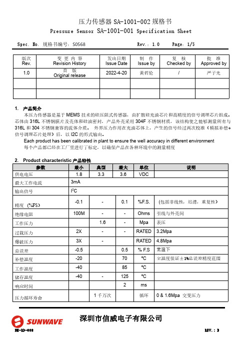
Spec.No.规格书编号:S0568Rev.:1.0Page:1/5深圳市信威电子有限公司版次Rev.变更内容Revision History发出日期Issue Date 制作Issue by 复核Checked by批准Approved by 1.0首版Original release2022-4-20黄哲伦/严子光1.产品简介本压力传感器是基于MEMS 技术的硅压阻式传感器,由扩散硅充油芯片和高精度的信号调理芯片组成。
芯体由316L 不锈钢膜片及壳体和硅油密封,产品外壳采用304F 不锈钢材质,该结构使之能够测量所有与316L 和304不锈钢兼容的流体介质。
外界压力作用在充油芯体上,产生的信号经过两次校准(模拟补偿+信号调理芯片处理)后,以I2C 的形式输出。
Each product has been calibrated in plant to ensure the well accuracy in different environment 每个产品都已经在工厂里进行了标定,以确保产品在各种环境中的测量精度Spec.No.规格书编号:S0568Rev.:1.0Page:2/5深圳市信威电子有限公司3.输出接口及管脚定义注:1.产品的内部电路已经在I2C 总线上放置了4.7K 的上拉电阻2.所有管脚与产品的金属外壳之间是绝缘的4.产品外形结构(单位:mm )5.功能描述5.1.工作模式传感器的默认工作模式为:产品上电后,进入到休眠状态,仅在接收到相应的I2C 命令后才会启动一次压力和温度的测量动作,之后再次自动进入休眠状态,以节省功耗。
5.2.上电启动及休眠唤醒当电源电压小于0.2V 时,传感器处于复位状态,在电源电压以最低10V/ms 的上升速率经过1ms 的延迟后,I2C 接口处于正常状态,可以接受主机命令,在经过2.5ms 的延迟后,传感器可以进行正常的压力和温度测量。
当传感器处于休眠状态时,在接收到主机命令后的0.5ms 时间内从休眠状态进入到工作模式,详细请参Spec.No.规格书编号:S0568Rev.:1.0Page:3/5深圳市信威电子有限公司照上电时序图6.I2C 接口6.1.I2C 接口电气特性在产品内部,I2C 总线的时钟信号线和数据线已经具有4.7k 的上拉电阻6.2.I2C 通讯速率本传感器的I2C 接口可工作于标准模式(100Kbit/s )、快速模式(400Kbit/s)、和高速模式(3.4Mbit/s)。
系列压力传感器操作手册

1. 设定参考输出状态:在量测模式下按
键超过四秒,屏幕出现
后放开,进入进阶设定模式。按
色的参考项目(详见进阶设定模式方块图)。按
键选择所要的参考项目。
键四下可看见设定颜
2. 颜色切换:在量测模式下按
键超过二秒,切入简易设定模式。按
键四下可看见设定显示颜色切换功能(详见简易设定模式
方块图)。按
键选择所要的显示颜色
注:「输出一 and 输出二」是当输出一以及输出二皆为 ON 时,才为 ON,否则皆为 OFF;「输出一 or 输出二」是当输出一以及输出二
皆为 OFF 时,才为 OFF,否则皆为 ON。
Code 代码
DPB 提供显示代码,供用户对照设定。在量测模式下按
键超过四秒,屏幕出现
下可看见显示代码(详见进阶设定模式方块图) 代码相关意义如下表:
键找到
,
设定所需的单位。
2. 输出状态:DPB 可设定两种输出状态,N.O.(常开)和 N.C.(常闭)。用户可在简易设定模式下,按 出一、二的输出状态。
键找到
,设定输
3. 反应时间设定:当压力达到输出状态时的反应时间。如设定为 50 代表当压力达到输出状态时必须维持 50ms,输出才会动作。用户可
6. 设定功能键 7. 向下调整键 8. 电源和输出信号端子 9. 压力输入气孔
DPB 1 2 量测压力范围 3 输出型式 4 压力气孔型式
台达 DPB 系列压力传感器 01: -100kPa ~ 100kPa, 10: -100kPa ~ 1,000kPa N: NPN output;P: PNP output P:外孔 PT 1/8、内孔 M5;N:外孔 NPT 1/8、内孔 M5;G:外孔 G 1/8、内孔 M5
- 1、下载文档前请自行甄别文档内容的完整性,平台不提供额外的编辑、内容补充、找答案等附加服务。
- 2、"仅部分预览"的文档,不可在线预览部分如存在完整性等问题,可反馈申请退款(可完整预览的文档不适用该条件!)。
- 3、如文档侵犯您的权益,请联系客服反馈,我们会尽快为您处理(人工客服工作时间:9:00-18:30)。
原理及特点通用参数应用■泵和压缩机■液压和气动■机床■机械制造■真空技术应用技术参数 (订货时用户可自定义量程)PN3010采用陶瓷厚膜传感器进行压力测量,信号由后部处理电路处理后转换成标准工业电信号输出并显示。
全金属外壳设计,采用高亮型LED 数字显示,使得该系列产品能够被用于各种工业场合。
双键设计和用户友好的菜单使产品使用更加方便。
多种连接方式可以充分满足各种特定的安装需求。
可330º旋转的显示头能保证在不同安装方式下获得最佳的观察角度。
·经济型产品·测量范围从0…1bar 到0…600bar ·4位LED 数字显示·全金属外壳·PNP/NPN 可设置·4...20mA/0…20mA 可设置;1…5V/0…5V 可设置·显示头可旋转N e x o n E l e c t r o n i c c a t a l o g P N 3010 c n v e r s i o n 1.0 2010 02设定面板窗口模式窗口模式下降过程中压力值要小于rP1时开关输出才释放。
窗口功能可使产品用来监视压力值是否超出一个特定的压力范围。
当压力值在rP1和SP1之间时,开关输出一种状态,而当压力值处于这个范围之外时开关输出另一种状态(与前一种相反)。
选型表i特殊要求可订制■用户指定的压力范围■G1/2, NPT1/2过程连接■食品卫生级法兰连接■用于粘性介质的齐平膜安装方式■加装用于高温介质的散热器■用户提出的其它电气,机械连接N e x o n E l e c t r o n i c c a t a l o g P N 3010 c n v e r s i o n 1.0 2010 02原理及特点通用参数应用■工程机械■液压和气动■机床■机械制造■泵和压缩机■石油钻探量程相关参数 (订货时用户可自定义量程)PN3020采用不锈钢薄膜传感器进行压力测量,信号由后部处理电路处理后转换成标准工业电信号输出并显示。
全金属外壳设计,采用高亮型LED 数字显示,使得该系列产品能够被用于各种工业场合。
双键设计和用户友好的菜单使产品使用更加方便。
多种连接方式可以充分满足各种特定的安装需求。
可330º旋转的显示头能保证在不同安装方式下获得最佳的观察角度。
·耐高压设计·测量范围从0…5bar 到0…2200bar ·4位LED 数字显示·全金属外壳·PNP/NPN 可设置·4...20mA/0…20mA 可设置;1…5V/0…5V 可设置·显示头可旋转N e x o n E l e c t r o n i c c a t a l o g P N 3020 c n v e r s i o n 1.0 2010 02设定面板窗口模式窗口模式下降过程中压力值要小于rP1时开关输出才释放。
窗口功能可使产品用来监视压力值是否超出一个特定的压力范围。
当压力值在rP1和SP1之间时,开关输出一种状态,而当压力值处于这个范围之外时开关输出另一种状态(与前一种相反)。
接线图N e x o n E l e c t r o n i c c a t a l o g P N 3020 c n v e r s i o n 1.0 2010 02选型表i特殊要求可订制■用户指定的压力范围■G1/2, NPT1/2过程连接■加装用于高温介质的散热器■用户提出的其它电气,机械连接N e x o n E l e c t r o n i c c a t a l o g P N 3020 c n v e r s i o n 1.0 2010 02·紧凑型设计·耐高压设计·测量范围从0…1bar 到0…1000bar 可选·抗强冲击设计·2线式或3线式可选·不锈钢或陶瓷触液部件原理及特点通用参数应用■液压和气动■机床■机械制造■泵和压缩机■测试台■建筑自动化量程相关参数 (订货时用户可自定义量程)PA1000采用陶瓷厚膜传感器(≤10b ar) 或 不锈钢薄膜传感器(>10bar )进行压力测量,信号由后部处理电路处理后转换成标准工业电信号输出。
全金属外壳设计,使得该系列产品能够被用于各种工业场合。
多种模拟输出类型可选:0...20mA, 4...20mA, 0...5V,1...5V 。
多种连接方式可以充分满足各种特定的安装需求。
N e x o n E l e c t r o n i c c a t a l o g P A 1000 c n v e r s i o n 1.0 2010 02尺寸图 inch(mm)接线图M12x1接插件直接附线mini 电磁阀插头N e x o n E l e c t r o n i c c a t a l o g P A 1000 c n v e r s i o n 1.0 2010 02选型表i特殊要求可订制■用户指定的压力范围■G1/2, NPT1/2过程连接■用户提出的其它电气,机械连接小型压力变送器PA1000N e x o n E l e c t r o n i c c a t a l o g P A 1000 c n v e r s i o n 1.0 2010 02·经济型产品·测量范围从0…1bar 到0…600bar ·结构紧凑·多种输出方式可选·不锈钢/陶瓷触液部件·抗腐蚀型可选·0.25%和0.5%精度可选原理及特点通用参数应用■液压和气动■机床■机械制造■泵和压缩机■测试台■建筑自动化量程相关参数 (订货时用户可自定义量程)PA2000采用陶瓷厚膜传感器(≤10bar)或金属薄膜传感器(≥10bar)进行压力测量,信号由后部处理电路处理后转换成标准工业电信号输出。
全金属外壳设计,使得该系列产品能够被用于各种工业场合。
多种模拟输出类型可选:0...20mA, 4...20mA,0...5V,1...5V,0…10V 。
多种连接方式可以充分满足各种特定的安装需求。
N e x o n E l e c t r o n i c c a t a l o g P A 2000 c n v e r s i o n 1.0 2010 02选型表i特殊要求可订制■用户指定的压力范围■G1/2, NPT1/2过程连接■食品卫生级法兰连接■用于粘性介质的齐平膜安装方式■加装用于高温介质的散热器■用户提出的其它电气,机械连接N e x o n E l e c t r o n i c c a t a l o g P A 2000 c n v e r s i o n 1.0 2010 02·经济型产品·测量范围从0…1bar 到0…600bar ·结构紧凑·多种输出方式可选·不锈钢/陶瓷触液部件·抗腐蚀型可选原理及特点通用参数应用■液压和气动■机床■机械制造■泵和压缩机■测试台■建筑自动化量程相关参数 (订货时用户可自定义量程)N e x o n E l e c t r o n i c c a t a l o g P A 3010 c n v e r s i o n 1.0 2010 02PA3010采用陶瓷厚膜传感器进行压力测量,信号由后部处理电路处理后转换成标准工业电信号输出。
全金属外壳设计,使得该系列产品能够被用于各种工业场合。
多种模拟输出类型可选:0...20mA, 4...20mA, 0...5V, 1...5V, 0…10V 。
多种连接方式可以充分满足各种特定的安装需求。
尺寸图 inch(mm)N e x o n接线图选型表i特殊要求可订制■用户指定的压力范围■G1/2, NPT1/2过程连接■食品卫生级法兰连接■用于粘性介质的齐平膜安装方式■加装用于高温介质的散热器■用户提出的其它电气,机械连接N e x o n E l e c t r o n i c c a t a l o g P A 3010 c n v e r s i o n 1.0 2010 02·耐高压设计·耐温范围宽-40…120℃·测量范围从0…5bar 到0…2200bar 可选·抗强冲击设计·2线式或3线式可选·不锈钢触液部件原理及特点通用参数应用■液压和气动■机床■机械制造■泵和压缩机■测试台■建筑自动化量程相关参数 (订货时用户可自定义量程)PA3020采用不锈钢薄膜传感器进行压力测量,信号由后部处理电路处理后转换成标准工业电信号输出。
全金属外壳设计,使得该系列产品能够被用于各种工业场合。
多种模拟输出类型可选:0...20mA, 4...20mA, 0...5V, 1...5V, 0…10V 。
多种连接方式可以充分满足各种特定的安装需求。
N e x o n E l e c t r o n i c c a t a l o g P A 3020 c n v e r s i o n 1.0 2010 02尺寸图 inch(mm)接线图N选型表i特殊要求可订制■用户指定的压力范围■G1/2, NPT1/2过程连接■加装用于高温介质的散热器■用户提出的其它电气,机械连接N e x o n E l e c t r o n i c c a t a l o g P A 3020 c n v e r s i o n 1.0 2010 02·紧凑型设计·HART 协议可选·测量范围从0…0.1bar 到0…70bar 可选·精度可达0.1%(0.05%型可定制)·抗腐蚀型可选·陶瓷电容测量元件·过载能力强原理及特点通用参数应用■石油■电力■化工■测试台■医药■污水处理接线图PA4000采用陶瓷电容传感器进行压力测量,信号由后部处理电路处理后转换成标准工业电信号输出。
全金属外壳设计,过载能力强,测量精度高,可选择抗腐蚀设计,可选HART输出。
该系列产品能够被石油,化工,医药,电力,污水处理等需要高精度及抗腐蚀要求的场合。
多种连接方式可以充分满足各种特定的安装需求。
N e x o n E l e c t r o n i c c a t a l o g P A 4000 c n v e r s i o n 1.0 2010 02选型表N e x o n E l e c t r o n i c c a t a l o g P A 4000 c n v e r s i o n 1.0 2010 02·紧凑型设计·高性价比·测量范围从0…0.1bar 到0…35bar 可选·精度为0.2%或0.5%·全金属外壳·气液两用型原理及特点通用参数应用■流量测量■加热或散热系统■建筑自动化■过滤堵塞检测■消防系统供水监控■污水处理■密闭罐体内的液位测量接线图PD2000紧凑型差压变送器,采用隔离型扩散硅差压传感器,基于惠斯登电桥原理,差压会改变应力测量元件的值,从而改变测量信号,该信号被集成电路处理后转换成工业标准电信号输出。