常用操作系统双网卡绑定方法
Windows 双网卡绑定

Windows 双网卡绑定第一步:硬件连接与安装首先进入BIOS设置将主板上集成的网卡打开,同时将独立网卡插入空闲的PCI插槽,用直通双绞线将两块网卡和宽带路由器的LAN口相连。
重新启动Windows XP系统,自动为两块网卡安装好驱动程序。
打开“网络连接”,会看到“本地连接”和“本地连接2”两个连接,而且这两个连接已经启用,硬件的连接与安装就算完成了。
第二步:绑定双网卡下载并安装绑定双网卡的软件“NIC Express”(下载地址/soft/36156.htm)。
在安装软件的过程中保持默认值,一路点击“Next”后,最后点击“Demo”就可以完成安装。
在将两块网卡绑定而虚拟出新设备的时候,会提示“未通过微软认证”,连续点击几次“仍然继续”按钮就可以继续安装。
弹出“绑定”窗口后(见图),在中间文本框中输入绑定后的连接名称(如“网卡绑定”),点击“Add”按钮将两块网卡加入到下面的“Assigned Adpaters”即可。
接着进入NIC Express的配置界面,保持默认值就可完成安装。
网卡绑定第三步:配置连接进入“网络连接”窗口,会看到多出了一个“网卡绑定NIC Express Virtual Adapter”的连接,并且已启用。
现在,这两块网卡已经成功绑定,可以右键点击“网卡绑定”,进行IP地址、子网、网关等参数的配置。
将IP地址设置为与路由器默认IP在同一网段,网关设置为路由器默认IP地址。
测速现在就可以进行BT下载的测试了。
以用BitComet下载一个350MB的热门电影为例。
打开数据流量窗口,可以从流量曲线监控图以及BitComet的“任务摘要”中看到两块网卡都在进行数据传输。
双网卡绑定组的传输速率从80KB/s起步,最高达到123KB/s,两块网卡的平均传输速率比较稳定,下载350MB的电影耗时23分钟,平均下载速度为110KB/s。
利用单网卡执行相同的下载任务,发现最高速度骤减到67KB/s,而且传输过程中的速率波动很大,下载这个350MB 的电影耗时49分钟,平均下载速度为79KB/s。
IBM3650windows双网卡绑定(实际操作版)

IBM3650 windows双网卡绑定
此配置满足windows系统的双网卡绑定和冗余功能,IBM服务器随即附带的光盘“Broadcom (R) NetXtreme II (TM) Gigabit Ethernet Software CD”
1.安装软件(DRIVER INSTALLER-网卡驱动程序);(MANAGEMENT APPLICATIONS-网卡应用程序及网卡绑定工具BASC,BASP。
)
点击下一步
以上为安装步骤,到此结束安装。
2.点击“开始”选择“Broadcom软件”。
选择“Team Management”标签。
在需要进行绑定的网卡(任意一块)上右键,选择“create team”创建绑定组。
按照默认点next
根据要求填写绑定网卡的名称(默认可不修改)
选择需要进行网卡绑定的物理网卡,点击ADD进行添加。
完毕后点击next
默认点
默认点NEXT
默认点EXIT
默认点NEXT
点击是确定配置。
完成后显示相关配置组。
关闭即可。
3.点击“开始-控制面板-网络连接”看到一个网卡名称为“Team 1”的网卡,按照正常网卡进行配置即可。
注意:之前绑定的两块网卡已无法进行IP配置,不要尝试进行修改IP!
4.验证绑定网卡测试,首先保证IP地址配置完成,并从起服务器。
1)网卡IP配置完毕后测试网关的连通性。
2)ping网关时,拔掉一个网卡口的网线,正常应该为继续通信状态。
(此方法测试另一端口)
用户服务中心-网络实验室
曹斌。
双网卡绑定方法

双网卡绑定方法下载并执行NICExpress的安装程序,待安装向导提示“Setup Type”时,选择“Enabled”(如图1),这样做的目的是启用网络负载平衡,当数据流量比较大时,该软件就会自动进行分流,使绑定的每块网卡都担当一定的任务,而不是把重任压在某一块网卡的身上。
小提示:如果是Windwos XP,那么在接下来的安装向导中可能会出现硬件无法通过兼容性测试,这里只要点击“仍然继续”按钮即可继续(如图2)。
根据安装向导的操作,待文件复制完毕即会进入绑定网卡设置窗口,可以看到窗口上方是计算机上已经安装的网卡,中间是设置组的名称,可以直接输入。
现在我们要做的就是在上方已经安装好的网卡列表中选中要绑定抽多卡,单击“Add”按钮,将其添加到“Assigned Adapters”框中去,被添加的网卡就是被绑定的网卡(如图3),添加好之后单击“OK”按钮,稍候片刻还会弹出一个参数设置窗口,在这里我们建议使用程序的默认参数即可。
三、应用设置现在我们绑定的网卡即可在工作了。
打开“网上邻居”的属性窗口,我们可以看到在原来物理网卡的基础上又多功能出一块虚拟的网卡(如图4)。
右击该网卡,选择“属性”命令打开网卡的设置窗口,我们可以看到在已安装的组件中多出一个“NIC Express Transport for Ethernet”,选中该项并单击“属性”按钮即可打开网卡绑定窗口,在这里我们可以增加其它绑定的网卡,也可以将绑定的网卡删除;如果打开“Internet协议(TCP/IP)”的属性窗口,那么还可以像普通网卡一样设置该虚拟网卡的IP地址等参数。
小提示:如果被绑定的网卡在绑定之前已经设置了IP地址,那么在绑定过程中程序会提示是否使用已经设置的IP地址。
四、综合应用现在我们就可以将两根网线连接到绑定的两块网卡,然后通过虚拟网卡的IP地址访问服务器,并进行操作,你就可以在网卡的指示灯上看到两个网卡都在进行数据交换。
双网卡绑定实现就是使用两块网卡虚拟成为一块网卡

双网卡绑定实现就是使用两块网卡虚拟成为一块网卡,这个聚合起来的设备看起来是一个单独的以太网接口设备,通俗点讲就是两块网卡具有相同的IP地址而并行链接聚合成一个逻辑链路工作。
根据交换机可支持的功能不通,最常见的是设定为主备方式的双网卡绑定。
一、操作步骤这里以绑定两个网卡为示例描述。
配置文件都在/etc/sysconfig/network-scripts/目录下。
1、编辑新的ifcfg-bond0文件增加如下内容:引用# cat /etc/sysconfig/network-scripts/ifcfg-bond0DEVICE=bond0IPADDR=192.168.1.155NETMASK=255.255.255.0ONBOOT=yesBOOTPROTO=noneUSERCTL=no这是最后bond0设备的实际IP设置。
2、分别编辑ifcfg-eth0和ifcfg-eth1文件引用# cat /etc/sysconfig/network-scripts/ifcfg-eth0DEVICE=eth0USERCTL=noONBOOT=yesMASTER=bond0SLAVE=yesBOOTPROTO=none# cat /etc/sysconfig/network-scripts/ifcfg-eth1DEVICE=eth1USERCTL=noONBOOT=yesMASTER=bond0SLAVE=yesBOOTPROTO=none3、修改/etc/modules.conf文件# vi /etc/modules.conf添加如下内容:引用alias bond0 bondingoptions bond0 miimon=100 mode=1说明:引用miimon是用来进行链路监测的。
比如:miimon=100,那么系统每100ms监测一次链路连接状态,如果有一条线路不通就转入另一条线路;mode的值表示工作模式,他共有0,1,2,3四种模式,常用的为0,1两种。
双网卡绑定
双网卡绑定
一.什么是双网卡绑定
双网卡绑定即使两块网卡具有相同的IP地址而并行链接聚合成一个逻辑链路工作
二.双网卡绑定的好处
1. 增大带宽
2. 保持带宽的稳定性
3. 可以形成网卡冗余阵列、分担负载,双网卡被绑定成“一块网卡”之后,同步一起工作,对服务器的访问流量被均衡分担到两块网卡上,这样每块网卡的负载压力就小多了,抗并发访问的能力提高,保证
了服务器访问的稳定和畅快,当其中一块发生故障的时候,另一块立刻接管全部负载,过程是无缝的,服务不会中断。
三.操作步骤
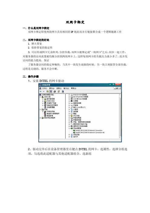
1、安装INTEL的网卡驱动
2、驱动完毕后在设备管理器里右键点INTEL的网卡,选属性,选择分组选
项,勾选将此适配器与其他适配器组合,选新组
3、添加组名(组名可以根据需要随意取)
4、单击下一步,选择组类型,此处选择适应性负载平衡。
5、下一步,勾选需要添加到组中的适配器
6、选择组模式,模式选适应性负载平衡,如果交换机支持链路聚合,选静态链路聚合也可以
7、设置组,选择主、从卡
8、在完成双网卡绑定以后在设备管理器中,网络适配器处会出现一个新的设备
“组:test”。
在本地连接中也将出现本地连接3。
四.遇到的问题以及解决方法
在绑定操作的最后一步中,单击完成后,系统则不再前进,无法完成绑定。
出现该问题的原因驱动版本过低,更新到最新版本的驱动程序后,问题解决。
Linux系统配置双网卡绑定bond0

Linux系统配置双⽹卡绑定bond01、bonding简述双⽹卡配置设置虚拟为⼀个⽹卡实现⽹卡的冗余,其中⼀个⽹卡坏掉后⽹络通信仍可正常使⽤,实现⽹卡层⾯的负载均衡和⾼可⽤性。
现在⼀般的企业都会使⽤双⽹卡接⼊,这样既能添加⽹络带宽,同时⼜能做相应的冗余,可以说是好处多多。
⽽⼀般企业都会使⽤linux操作系统下⾃带的⽹卡绑定模式,当然现在⽹卡产商也会出⼀些针对windows操作系统⽹卡管理软件来做⽹卡绑定(windows操作系统没有⽹卡绑定功能需要第三⽅⽀持)。
1.1 bonding原理⽹卡⼯作在混杂(promisc)模式,接收到达⽹卡的所有数据包,tcpdump⼯作⽤的也是混杂模式(promisc),将两块⽹卡的MAC地址修改为相同接收特定MAC的数据帧,然后把相应的数据帧传送给bond驱动程序进⾏处理。
1.2 Bonding模式(bonding mode)轮询策略(round robin),mode=0,按照设备顺序依次传输数据包,提供负载均衡和容错能⼒主备策略(active-backup),mode=1,只有主⽹卡处于⼯作状态,备⽹卡处于备⽤状态,主⽹卡坏掉后备⽹卡开始⼯作,提供容错能⼒异或策略(load balancing (xor)),mode=2,根据源MAC地址和⽬的MAC地址进⾏异或计算的结果来选择传输设备,提供负载均衡和容错能⼒⼴播策略(fault-tolerance (broadcast)),mode=3,将所有数据包传输给所有接⼝通过全部设备来传输所有数据,⼀个报⽂会复制两份通过bond下的两个⽹卡分别发送出去,提供⾼容错能⼒动态链接聚合(lacp),mode=4,按照802.3ad协议的聚合⾃动配置来共享相同的传输速度,⽹卡带宽最⾼可以翻倍,链路聚合控制协议(LACP)⾃动通知交换机聚合哪些端⼝,需要交换机⽀持 802.3ad协议,提供容错能⼒输出负载均衡模式(transmit load balancing),mode=5,输出负载均衡模式,只有输出实现负载均衡,输⼊数据时则只选定其中⼀块⽹卡接收,需要⽹卡和驱动⽀持ethtool命令输⼊/输出负载均衡模式(adaptive load balancing),mode=6,输⼊和输出都实现负载均衡,需要⽹卡和驱动⽀持ethtool命令2、⽹卡配置⽂件的配置2.1 配置环境 环境:系统CentOS 6.7 + 虚拟机 VMware 12 ⾄少两块物理⽹卡(VMware上添加eth0,eth1) 2.2 需要添加或修改的配置⽂件有5个(mode=1) 这5个配置⽂件是: /etc/sysconfig/network-scripts/ifcfg-eth{0,1} /etc/sysconfig/network-scripts/ifcfg-bond0 /etc/modprobe.d/dist.conf /etc/rc.local2.2.1 /etc/sysconfig/network-scripts/ifcfg-{eth0,eth1,bonding0}修改或添加提⽰:先备份好eth0和eth1,再修改这⼏个⽂件以下是修改好的三个⽹卡配置⽂件的参数[root@ant network-scripts]# vimdiff ifcfg-eth0 ifcfg-eth1 ifcfg-bond02.2.2 修改/etc/modprobe.d/dist.conf⽂件在此⽂件中添加以下内容:alias bond0 bonding,表⽰系统在启动时加载bonding模块,对外虚拟⽹络接⼝设备为 bond0miimon=100,表⽰系统每100ms监测⼀次链路连接状态,如果有⼀条线路不通就转⼊另⼀条线mode=1,表⽰绑定模式为1primary=eth0,系统⾸先eth0作为bond0接⼝与外界信息的传输接⼝2.2.3 修改配置⽂件/etc/rc.local在此⽂件中添加以下内容:modprobe bonding miimon=100 mode=12.2.4 重启⽹络(service network restart),并查看三个接⼝的mac地址使⽤ifconfig命令显⽰,bond0,eth1,eth2物理地址相同,提⽰三个⽹卡均通过⼀个ip主机端⼝与外界通信但是,我们可以看到,在mode=1的情况下,当前bond0采⽤eth0通信,实际的物理⽹卡地址见下图:3、验证⽹络的连通性没有丢包,⽹络连通性可。
双线路双网卡双网关如何设置
双线路双网卡双网关如何设置双线路双网卡双网关是一种网络配置方式,允许一台设备同时连接两个不同的网络,并使用两个不同的网关进行数据传输。
这种配置可以提高网络的可靠性和带宽利用率,适用于需要同时访问多个网络的场景,如企业办公网络、数据中心等。
要设置双线路双网卡双网关,需要进行以下步骤:1.确定网络架构:首先需要明确要连接的两个网络的架构和拓扑结构,包括IP地址分配、子网掩码、网关地址等。
确保两个网络不冲突。
2.准备设备和网络接口:在配置之前,需要确保设备上有两个可用的网络接口(通常是网卡或无线网卡),分别连接到两个网络中的交换机或路由器。
3.配置网络接口:进入设备的操作系统中,找到网络设置界面,对两个网络接口进行配置。
通常可以通过命令行或图形界面进行设置。
a.为每个网络接口分配对应的IP地址、子网掩码和网关地址。
确保两个接口的IP地址不冲突,并且网关地址是所连接网络的路由器IP地址。
b.可以为每个接口设置DNS服务器地址,用于解析域名。
也可以不设置DNS服务器,直接使用IP地址进行访问。
c.注意设置本地路由表,确保数据流量正确发送到网关。
4.配置多网关策略:在设备的操作系统中,需要设置双网卡双网关的路由策略,以确保数据能够正确流向两个网络。
a. 可以使用操作系统提供的多网关策略,如Linux中的多路由表(multiple routing tables)或Windows中的多网关路由(multiple gateway routing)。
b.根据实际需求,可以设置策略路由表,指定不同的目标IP地址流向不同的网关。
例如,将内部办公网流量指向一个网关,将外部互联网流量指向另一个网关。
c.根据实际需求,可以设置策略路由规则,对特定的IP地址或域名进行特殊处理。
例如,将特定的IP地址流量直接发送到其中一个网关,而不经过默认网关。
5.测试和调试:完成以上配置后,需要进行测试和调试,确保双线路双网卡双网关的设置正常工作。
SUSE-11图形界面操作双网卡绑定
SUSE 11图形界面操作双网卡绑定1.输入yast2登入图形界面,选择Network Settings点击进去2.选择Overview中Add,进去选择Bond,并进行网卡命名后进行下一步3.在静态地址中输入你所需要指定的IP,选择Bond Slaves4.将两块网卡选择为绑定网卡,并选择参数。
(下面会将每个参数作解释,根据实际需求选择)balance-rr (mode=0)轮转(Round-robin)策略:从头到尾顺序的在每一个slave接口上面发送数据包。
本模式提供负载均衡和容错的能力。
active-backup(mode=1)活动-备份(主备)策略:在绑定中,只有一个slave被激活。
当且仅当活动的slave 接口失败时才会激活其他slave。
为了避免交换机发生混乱此时绑定的MAC地址只有一个外部端口上可见。
在bongding的2.6.2及其以后的版本中,主备模式下发生一次故障迁移时,bonding将在新激活的slave上会送一个或者多个gratuitous ARP.bonding的主salve接口上以及配置在接口上的所有VLAN接口都会发送gratuitous ARP,只要这些接口上配置了至少一个IP地址。
VLAN接口上发送的的gratuitous ARP将会附上适当的VLAN id。
本模式提供容错能力,primary option,documented below会影响本模式的行为。
balance-xor(mode=2)XOR策略:基于所选择的传送hash策略。
本模式提供负载均衡和容错的能力。
broadcast(mode=3)广播策略:在所有的slave接口上传送所有的报文。
本模式提供容错能力。
802.3ad(mode=4)IEEE 802.3ad 动态链路聚合。
创建共享相同的速率和双工模式的聚合组。
能根据802.3ad 规利用所有的slave来建立聚合链路。
Salve的出站选择取决于传输的hash策略,默认策略是简单的XOR策略,而hash策略则可以通xmit_hash_policy选项加以改变。
双网卡绑定一个IP的方法
双网卡冗余技术
——双网卡绑定一个IP的方法在装有Realtek两个网卡的Windows XP服务器中可以将两个网卡绑定,设置成一个IP 地址,有效均衡负载和提高容错能力,避免服务器在出现传输瓶颈或因某块网卡故障而停止服务。
将两块网卡绑定在同一个IP地址上,同步一起工作,当其中一块发生故障的时候,另一块网卡立刻接管全部负载,过程是无缝的,服务不会中断。
下面介绍软件设置方法
1.打开EXE_Teaming_Green(Normal)文件夹,setup.exe默认安装
2.打开WINXP 文件夹→32文件夹→EXE文件夹→8169Diag 出现网卡诊断管理界面按照下图操作即可
在网络连接发现多出一个本地连接这个网卡为绑定后的网卡组,这个网卡的使用和使用单一网卡完全一样,相当于一个单一网卡的“虚拟网卡”。
如下图:
可以改定此虚拟网卡的IP地址、子网掩码、网关等等。
麒麟系统双网卡绑定配置
麒麟操作系统技术总结一、网卡绑定当系统中有多个网卡需要进行设置时,建议将网卡的MAC地址与ethX 文件种的HWADDR一一对应,否则系统重启后网卡的eth号很可能会发生改变,在设置了网卡绑定的生成系统中,这是非常危险的。
网卡绑定配置(如将网卡eth1和eth3绑定为bond0的操作步骤):(1)使用service NetworkManage stop命令关闭NetworkManage服务,使用chkconfig NetworkManage off命令使NetworkManage服务在系统开机时不自动启动;(2)修改被绑定网卡eth1的配置。
打开终端,使用cd /etc/sysconfig/network-scripts命令进入network-scripts目录,使用gedit ifcfg-eth1命令打开ifcfg-eth1文件,修改以下内容,修改完成后保存并关闭ifcfg-eth1文件。
DEVICE=eth1BOOTPROTO=noneHWADDR=”: ::::”ONBOOT=yesTYPE=EthernetUSERCTL=noIPV6INIT=noPEERDNS=yesSLA VE=yesMASTER=bond0备注:DEVICE=<name>:<name>表示物理设备的名称,对于动态寻址的PPP设备则是指它的逻辑名称。
BOOTPROTO=<protocol><protocol>的值有以下几种:none——不自定启用协议bootp——使用BOOTP协议dhcp——使用DHCP协议HWADDR:网卡的MAC地址ONBOOT=<yes | no>:yes表示系统启动时激活设备;no表示系统启动时不激活设备USERCTL=<yes | no>:yes表示允许非root用户控制这个设备;no表示不允许非root用户控制这个设备;PEERDNS=<yes | no>:yes表示使用DNS选项的值代替/etc/resolv.conf中的配置。
- 1、下载文档前请自行甄别文档内容的完整性,平台不提供额外的编辑、内容补充、找答案等附加服务。
- 2、"仅部分预览"的文档,不可在线预览部分如存在完整性等问题,可反馈申请退款(可完整预览的文档不适用该条件!)。
- 3、如文档侵犯您的权益,请联系客服反馈,我们会尽快为您处理(人工客服工作时间:9:00-18:30)。
常用操作系统双网卡绑定方法目录一、RHEL 5.7 LINUX 下网卡绑定设置 (1)二、RHEL6 LINUX 下网卡绑定设置 (3)三、SUSE 10 下网卡绑定设置 (11)四、SUSE 11 下网卡绑定设置 (16)五、Windows 下网卡绑定设置 (22)一、RHEL 5.7 LINUX 下网卡绑定设置[root@Linux5 ~]# more /etc/sysconfig/network-scripts/ifcfg-bond0# Broadcom Corporation NetXtreme II BCM5709S Gigabit EthernetDEVICE=bond0BOOTPROTO=staticONBOOT=yesIPADDR=10.96.19.207NETMASK=255.255.255.0GATEWAY=10.96.19.1TYPE=Ethernet[root@Linux5 ~]# more /etc/sysconfig/network-scripts/ifcfg-eth0# Broadcom Corporation NetXtreme II BCM5709S Gigabit EthernetDEVICE=eth0BOOTPROTO=noneHWADDR=34:40:B5:BD:24:18ONBOOT=yesMASTER=bond0SLAVE=yesTYPE=Ethernet[root@Linux5 ~]# more /etc/sysconfig/network-scripts/ifcfg-eth1# Broadcom Corporation NetXtreme II BCM5709S Gigabit EthernetDEVICE=eth1BOOTPROTO=noneHWADDR=34:40:B5:BD:24:1AONBOOT=yesMASTER=bond0SLAVE=yesTYPE=Ethernet[root@Linux5 ~]# more /proc/net/bonding/bond0Ethernet Channel Bonding Driver: v3.4.0-1 (October 7, 2008)Bonding Mode: fault-tolerance (active-backup)Primary Slave: NoneCurrently Active Slave: eth0MII Status: upMII Polling Interval (ms): 100Up Delay (ms): 0Down Delay (ms): 0Slave Interface: eth0MII Status: upSpeed: 1000 MbpsDuplex: fullLink Failure Count: 6Permanent HW addr: 34:40:b5:bd:24:18Slave Interface: eth1MII Status: downSpeed: 1000 MbpsDuplex: fullLink Failure Count: 6Permanent HW addr: 34:40:b5:bd:24:1a[root@Linux5 ~]# more /etc/modprobe.confalias eth0 bnx2alias eth1 bnx2alias eth2 bnx2alias eth3 bnx2alias scsi_hostadapter mptbasealias scsi_hostadapter1 mptsasalias scsi_hostadapter2 usb-storagealias net-pf-10 offalias ipv6 offoptions ipv6 disable=1alias usb0 usbnetalias usb1 usbnetalias bond0 bondingoptions bond0 miimon=100 mode=1 primary=eth0关于路由的配置,做如下说明,1)使用route 命令添加的路由,机器重启或者网卡重启后路由就失效了,方法://添加到主机的路由# route add –host 192.168.168.110 dev eth0# route add –host 192.168.168.119 gw 192.168.168.1//添加到网络的路由# route add –net IP网段 netmask MASK eth0# route add –net IP网段 netmask MASK gw IP# route add –net IP网段 /24 eth1//添加默认网关# route add default gw IP//删除路由# route del –host 192.168.168.110 dev eth02)在linux下设置永久路由的方法(选其一即可)a. 将命令写入开机脚本/etc/rc.localb. route add -net 192.168.3.0/24 dev eth0route add -net 192.168.2.0/24 gw 192.168.3.254c. /etc/sysconfig/static-router :any net x.x.x.x/24 gw y.y.y.y二、RHEL6 LINUX 下网卡绑定设置To configure the bond0 device with the network interface eth0 and eth1, perform the following steps:1. Create a new file as root named bonding.conf in the /etc/modprobe.d/ directory. Insert the following line in this new file:alias bond0 bonding2. Create the channel bonding interface file ifcfg-bond0 inthe/etc/sysconfig/network-scripts/ directory:# cat /etc/sysconfig/network-scripts/ifcfg-bond0DEVICE=bond0IPADDR=192.168.50.111NETMASK=255.255.255.0USERCTL=noBOOTPROTO=noneONBOOT=yesBONDING_OPTS="mode=1 miimon=100"Note:Configure the bonding parameters in the file /etc/sysconfig/network-scripts/ifcfg-bond0, as above, BONDING_OPTS="mode=0 miimon=100".The behavior of the bonded interfaces depends upon the mode. The mode 0 is the default value, which causes bonding to set all slaves of an active-backup bond to the same MAC address at enslavement time. For more information about the bonding modes, refer to The bonding modes supported in Red Hat Enterprise Linux.3. Configure the ethernet interface in the file/etc/sysconfig/network-scripts/ifcfg-eth0. Both eth0 and eth1 should look like thefollowing example:DEVICE=eth<N>BOOTPROTO=noneHWADDR=54:52:00:26:90:fcONBOOT=yesMASTER=bond0SLAVE=yesUSERCTL=no4. Restart the network service:# service network restartNote:It may be necessary to disable NetworkManager if you find that bonding is not working properly. To do this, you would run the following:# service NetworkManager stop# chkconfig NetworkManager off# service Network restart5. In order to check the bonding status, check the following file:# cat /proc/net/bonding/bond0Multiple bonded deviceConfiguring multiple bonding channels is similar to configuring a single bonding channel. Setup the ifcfg-bond<N> and ifcfg-eth<X> files as if there were only one bonding channel. You can specify different BONDING_OPTS for different bonding channels so that they can have different modes and other settings. Refer to the section 4.2.2. Channel Bonding Interfaces in the Red Hat Enterprise Linux 6 Deployment Guide for more information.To configure the bond0 device with the ethernet interface eth0 and eth1, and configure the bond1 device with the Ethernet interface eth2 and eth3, perform the following steps: 1. Create configuration file /etc/modprobe.d/bonding.conf with the following lines: alias bond0 bondingalias bond1 bonding2. Create the channel bonding interface files ifcfg-bond0 and ifcfg-bond1, in the/etc/sysconfig/network-scripts/ directory:# cat /etc/sysconfig/network-scripts/ifcfg-bond0DEVICE=bond0IPADDR=192.168.50.111NETMASK=255.255.255.0USERCTL=noBOOTPROTO=noneONBOOT=yesBONDING_OPTS="mode=1 miimon=100"# cat /etc/sysconfig/network-scripts/ifcfg-bond1DEVICE=bond1IPADDR=192.168.30.111NETMASK=255.255.255.0USERCTL=noBOOTPROTO=noneONBOOT=yesBONDING_OPTS="mode=1 miimon=50"Note: there are different bonding modes for bond0 and bond1. For the bond0 device, it is the balance-rr policy (mode=0).For the bond1 device, it is the fail_over_mac policy (mode=1). More information about the bonding modes please refer to The bonding modes supported in Red Hat Enterprise Linux3. Configure the ethernet interface in the file/etc/sysconfig/network-scripts/ifcfg-eth0. Both eth0 and eth1 should look like thefollowing example:DEVICE=eth<N>BOOTPROTO=noneHWADDR=54:52:00:26:90:fcONBOOT=yesMASTER=bond0SLAVE=yesUSERCTL=noNote:Replace <N> with the numerical value for the interface, such as 0 and 1 in this example. Replace the HWADDR value with the MAC for the interface.Red Hat suggest that configure the MAC address of the ethernet card into the file /etc/sysconfig/network-scripts/ifcfg-eth<N>.4. Restart the network service:# service network restart5. In order to check the bonding status, check the following file:# cat /proc/net/bonding/bond0Bonding modesBalance-rr (mode 0)Round-robin policy: transmits packets in sequential order from the first available slave through the last.∙This mode provides load balancing and faulttolerance.Active-backup (mode 1)Active-backup policy: only one slave in the bond is active. A different slave becomes active only if the active slave fails. The bond's MAC address is externally visible on only one port (network adapter) to avoid confusing the switch.In bonding version 2.6.2 or later, when a failover occurs in active-backup mode, bonding will issue one or more gratuitous ARPs on the newly active slave. One gratuitous ARP is issued for the bonding master interface and each VLAN interface configured above it, assuming that the interface has at least one IP address configured. Gratuitous ARPs issued for VLAN interfaces are tagged with the appropriate VLAN id.∙This mode provides fault tolerance.∙The primary option, affects the behavior of thismode.Balance-xor (mode 2)XOR policy: transmits based on the selected transmit hash policy. The default policy is a simple ((source MAC address XORd with destination MAC address) modulo slave count) . Alternate transmit policies may be selected via the xmit_hash_policy option, described below.∙This mode provides load balancing and faulttolerance.Broadcast (mode 3)Broadcast policy: transmits everything on all slave interfaces.∙This mode provides fault tolerance.802.3ad (mode 4)IEEE 802.3ad dynamic link aggregation: this mode creates aggregation groups that share the same speed and duplex settings, and uses all slaves in the active aggregator according to the 802.3ad specification. Slave selection for outgoing traffic is done according to the transmit hash policy, which may be changed from the default simple XOR policy via the xmit_hash_policy option, documented below. Note that not all transmit policies may be 802.3ad compliant, particularly with regard to the packet misordering requirements described in section 43.2.4 of the 802.3ad standard. Differing peer implementations will have varying tolerances for noncompliance. Prerequisites:∙ethtool support in the base drivers for retrieving thespeed and duplex of each slave∙ a switch that supports IEEE 802.3ad Dynamic linkaggregation.∙Most switches will require some type of configurationto enable 802.3ad mode.Balance-tlb (mode 5)Adaptive transmit load balancing: channel bonding that does not require any special switch support. The outgoing traffic is distributed according to the current load (computed relative to the speed) on each slave. Incoming traffic is received by the current slave. If the receiving slave fails, another slave takes over the MAC address of the failed receiving slave.Prerequisite:∙ethtool support in the base drivers for retrieving thespeed of each slave.Balance-alb (mode 6)Adaptive load balancing: includes balance-tlb and receive load balancing (rlb) for IPv4 traffic, and does not require any special switch support. The receive load balancing is achieved by ARP negotiation. The bonding driver intercepts the ARP replies sent by the local system on their way out and overwrites the source hardware address with the unique hardware address of one of the slaves in the bond, such that different peers use different hardware addresses for the server.Receive traffic from connections created by the server is also balanced. When the local system sends an ARP request the bonding driver copies and saves the peer's IP information from the ARP packet. When the ARP reply arrives from the peer, its hardware address is retrieved and the bonding driver initiates an ARP reply to this peer assigning it to one of the slaves in the bond. A problematic outcome of using ARP negotiation for balancing is that each time that an ARP request is broadcast it uses the hardware address of the bond. Hence, peers learn the hardware address of the bond and the balancing of receive traffic collapses to the current slave. This is handled by sending updates (ARP Replies) to all the peers with their individually assigned hardware address such that the traffic is redistributed. Receive traffic is also redistributed when a new slave is added to the bond and when an inactive slave is reactivated. The receive load is distributed sequentially (round-robin) among the group of highest-speed slaves in the bond.When a link is reconnected or a new slave joins the bond the receive traffic is redistributed among all active slaves in the bond by initiating ARP Replies with the selected MAC address to each of the clients. The updelay parameter (detailed below) must be set to a value equal or greater than the switch's forwarding delay so that the ARP Replies sent to the peers will not be blocked by the switch.Prerequisites:ethtool support in the base drivers for retrieving thespeed of each slave∙base driver support for setting the hardware addressof a device while it is open. This is required so thatthere will always be one slave in the team using thebond hardware address (the curr_active_slave) whilehaving a unique hardware address for each slave inthe bond. If the curr_active_slave fails its hardwareaddress is swapped with the new curr_active_slavethat was chosen.Bonding parameters in generalIt is critical that either the miimon or arp_interval and arp_ip_target parameters be specified, otherwise serious network degradation will occur during link failures. Very few devices do not support at least miimon, so it should always be used.General bonding parametersmax_bonds: specifies the number of bonding devices to create for this instance of the bonding driver. For example, if max_bonds is 3, and the bonding driver is not already loaded, then bond0, bond1 and bond2 will be created. The default value is 1.ARP monitoring parameters∙arp_interval: specifies the ARP link monitoringfrequency in milliseconds.∙arp_ip_target: specifies the IP addresses to use asARP-monitoring peers when arp_interval is > 0.Multiple IP addresses must be separated by a comma.At least one IP address must be given for ARPmonitoring to function. The maximum number oftargets that can be specified is 16.∙arp_validate: specifies whether or not ARP probesand replies should be validated in the active-backupmode. This causes the ARP monitor to examine theincoming ARP requests and replies, and only considera slave to be up if it is receiving the appropriate ARPtraffic. This parameter can have the followingvalues:o none (0). This is the default.o active (1). Validation is performed only for theactive slave.o backup (2). Validation is performed only for backupslaves.o all (3). Validation is performed for all slaves.三、SUSE 10 下网卡绑定设置命令方式如下1)、配置网卡bondingA、在/etc/sysconfig/network 下建立bond0 配置文件,设置好网络地址,网关子网掩码#vi /etc/sysconfig/network/ifcfg-bond0BOOTPROTO='static'BROADCAST=''#此参数无需设置IPADDR='10.30.43.4'NETMASK='255.255.255.128'NETWORK=''#此参数最好在网关配置文件里配置,这里无需设置BONDING_MASTER='yes'BONDING_MODULE_OPTS='mode=active-backup miimon=100'BONDING_SLAVE0='bus-pci-0000:06:08.1'#如果能确认网卡总线可以这么设置,也可以采用MAC地址方式,如BONDING_SLAVE0='id-00:0c:29:3b:f8:4b'BONDING_SLAVE1='bus-pci-0000:06:09.1'STARTMODE='auto'USERCONTROL='no'B、修改需要绑定的两个网卡的配置文件#可以直接删除两个网卡的配置文件#vi /etc/sysconfig/network/ifcfg-eth-id-xx:xx:xx:xx:xx:xx,BOOTPROTO='none'STARTMODE='off'C、输入#cat /proc/net/bonding/bond0看网卡工作状态,查看到bond0,eth0,eth1是否正常2)、网络信息设置A、编辑网关的配置,建议在默认路由里配置#vi /etc/sysconfig/network/routesdefault 10.25.5.254 - -b、设置ip地址通过 yast2 lan 进行设置。