通用接近开关E2E
欧姆龙接近开关E2E-X4MD1

欧姆龙接近开关E2E-X4MD1简介欧姆龙接近开关E2E-X4MD1是一种非接触式传感器,用于检测物体是否接近开关,通常用于自动化控制系统。
该开关采用磁感应原理工作,可以识别铁质和非铁质材料。
E2E-X4MD1是欧姆龙公司生产的一款具有高可靠性和长寿命的接近开关,广泛应用于工业自动化和机器人控制系统。
构成E2E-X4MD1接近开关由四个主要部分组成:1.感应面:用于检测物体是否接近开关,通常为金属材料。
2.感应元件:用于转换感应面的信号为电信号,通常为磁敏元件。
3.电路板:用于处理并放大电信号,通常为数字电路。
4.脚座:用于连接电源和控制器,通常为插头或接线端子。
工作原理E2E-X4MD1接近开关采用磁感应原理工作。
当感应面靠近磁敏元件时,感应面产生的磁场会影响磁敏元件的磁场,从而引起感应元件中感应电动势的变化。
感应元件将变化的电信号输出到电路板上,经过电路板的处理和放大,然后输出到控制器上。
技术参数E2E-X4MD1接近开关的技术参数如下:•检测距离:4mm•接头类型:M12插座•工作电压范围:10~30VDC•感应物体:铁质或非铁质材料•最大开关频率:1000Hz•最大开关电流:200mA•最大负载电压:30VDC•工作温度范围:-25℃~70℃•保护等级:IP67应用场景E2E-X4MD1接近开关广泛应用于以下领域:1.工业自动化控制系统:可用于自动控制输送带或流水线的开关,以检测物体的位置和传送状态。
2.机器人控制系统:可用于检测机器人的位置和操作状态,以调整机器人的动作和速度。
3.食品加工和制药行业:可用于检测食品或药品的位置和状态,以保证产品质量和安全性。
4.包装行业:可用于自动控制包装机械,以准确地控制包装材料和产品的位置和数量。
总结E2E-X4MD1接近开关是欧姆龙公司生产的一款高可靠性和长寿命的非接触式传感器,采用磁感应原理工作,可以检测铁质和非铁质材料的位置和状态。
该接近开关广泛应用于工业自动化和机器人控制系统,以及食品加工、制药和包装行业。
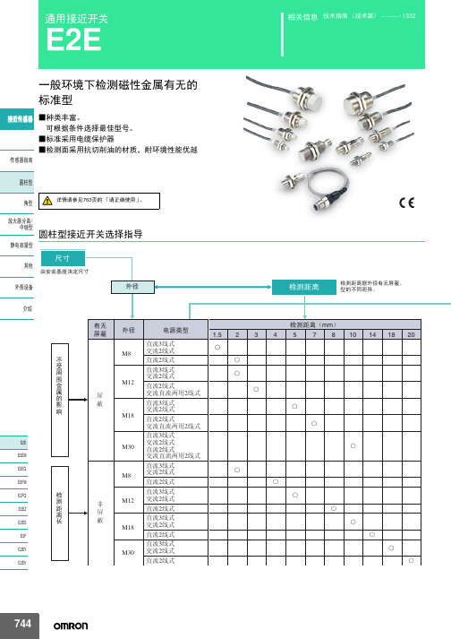
欧姆龙E2E通用接近开关详解
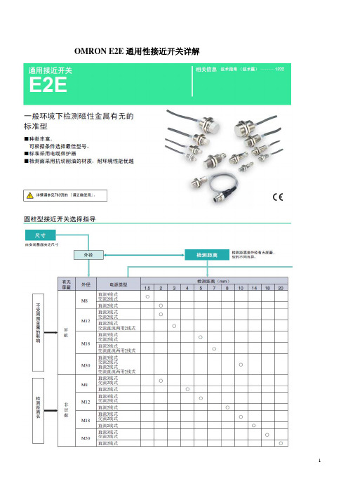
OMRON E2E通用性接近开关详解
现购有:E2E-X10E2 NPN NC型,E2E-X10F1 PNP NO型。
屏蔽型M30螺纹。
现购有:E2E-X10E2 NPN NC型,E2E-X10F1 PNP NO型。
NPN有两种形式:E1为NPN NO型,E2为NPN NC型。
PNP有一种形式:F1为PNP NO型。
E2E-X10E2 NPN NC E2E-X10E1 NPN NO E2E-X10F1 PNP NO
所谓NO、NC均对接近开关在无动作时-即常态时的开关管的状态而言,例如:对于NPN NC无动作时,②端对③端呈闭合状态即NC,此时①端、②端得电。
对于NPN NO无动作时,④端对③端呈开路状态即NO,此时④端、①端失电。
对于PNP NO无动作时,褐色端对黑色端呈开路状态即NO,此时黑色端、蓝色端失电。
对于常开或常闭,可以将开关管的发射极和集电极等效为一个开关。
依据传统的限位开关具有二对触点,一对为常开、而另一对为常闭。
因此、可以选用4芯接插件形式,通过不同的接线方式
例如:E2E-X10E1-M1或E2E-X10E1-M3,完成NPN NO、NPN NC 兼容的功能。
而对于集电极开路传感器的的接法见下图:
E2E-C/X_C_ NPN NC/NO E2E-C/X_B_ PNP NO。
omron E2E通用接近开关 说明书
10mm 8mm
E2E-X10D1S-M1
D
——
—
E2E-X8MD1S-M1
D
——
—
M18
14mm
E2E-X14MD1S-M1
D
——
—
M30
20mm
E2E-X20MD1S-M1
D
——
—
M8
2mm
M12
ሣ㬑
M12 3mm
E2E-X2D1-M1G
A E2E-X2D2-M1G
D
E2E-X3D1-M1G *1
㾦ൟ
ᬒ఼ߚ行 Ё㒻ൟ
M30
10mm
无
M8
4mm
䴲ሣ㬑
M12
8mm
M18
14mm
E2E-X10D1-N E2E-X4MD1 E2E-X8MD1 E2E-X14MD1
*1*2*3 *2*3 *1*2*3 *1*2*3
E2E-X10D2-N E2E-X4MD2 E2E-X8MD2 E2E-X14MD2
ሣ㬑
1.5mm
E2E-X1R5E1-M3
M8 䴲ሣ㬑
M8 2mm
E2E-X2ME1-M3
输出形态PNP NO E2E-CR8B1 E2E-X1B1 E2E-C1B1 E2E-X1R5F1 E2E-X2F1 E2E-X5F1 E2E-X10F1 E2E-X2MF1 E2E-X5MF1 E2E-X10MF1 E2E-X18MF1
Ⳉ⌕2㒓ᓣ
ƻ ƻ
Ⳉ⌕3㒓ᓣ M18 Ѹ⌕2㒓ᓣ
Ⳉ⌕2㒓ᓣ
ƻ ƻ
Ⳉ⌕3㒓ᓣ M30 Ѹ⌕2㒓ᓣ
Ⳉ⌕2㒓ᓣ
ƻ ƻ
744
E2E
⬉⑤䕧ߎ Փ⫼⦃๗
E2E微型靠近传感器产品参数说明书

1E2E High performance in small sizes•pre-wired and M8 connector models •3mm, 4mm, 5.4mm and M5 sizes •response frequency up to 3kHzOrdering InformationSizeSensing Distance Connection Housing Material OutputOperation mode NO Operation mode NC dia 3mm shielded0.6mm pre-wired stainless steelPNP E2E-CR6B1E2E-CR6B2NPN E2E-CR6C1E2E-CR6C2dia 4mm0.8mmpre-wired PNP E2E-CR8B1E2E-CR8B2NPN E2E-CR8C1E2E-CR8C2M8 connectorPNP E2E-CR8B1-M5E2E-CR8B2-M5NPN E2E-CR8C1-M5E2E-CR8C2-M5M51mmpre-wired brassPNP E2E-X1B1E2E-X1B2NPN E2E-X1C1E2E-X1C2M8 connectorPNP E2E-X1B1-M5E2E-X1B2-M5NPN E2E-X1C1-M5E2E-X1C2-M5dia 5.4mmpre-wiredPNP E2E-C1B1E2E-C1B2NPNE2E-C1C1E2E-C1C22Inductive SensorsSpecificationsE2E-C @C @/B @, E2E-X1C @/B @ DC 3-wire ModelsNote:The response speed is an average value. Measurement conditions are as follows: standard sensing object, a distance of twice the standardsensing object, and a set distance of half the sensing distance.Size 3 dia.4 dia.M55.4 dia.TypeShieldedItemE2E-CR6C @/B @E2E-CR8C @/B @E2E-X1C @/B @E2E-C1C @/B @Sensing distance 0.6mm ±15%0.8 mm ±15% 1 mm ±15%Set distance 0 to 0.4mm0 to 0.5 mm0 to 0.7 mmDifferential travel 15% max. of sensing distanceSensing objectFerrous metal (The sensing distance decreases with non-ferrous metal, refer to Engineering Data .)Standard sensing object Iron: 3x3x1 mm Iron: 5x5x1mm Response speed (See note.)2kHz3kHzPower supply voltage (operating voltage range)12 to 24 VDC (10 to 30 VDC), ripple (p-p): 10% max.Current consumption 10mA max.17 mA max.Control output Load currentOpen-collector output, 80mA max.(at 30VDC max.)Open-collector output 100 mA max. (at 30 VDC max.)Residual voltage1 VDC max.(Load current: 80mA, Cable length: 2m)2 VDC max. (Load current: 100 mA , Cable length: 2 m)IndicatorOperation indicator (red LED)Operation mode (with sensing object approaching)C1/-B1 Models:NO C2/-B2 Models:NCFor details, refer to Timing Charts .Protection circuits Power supply reverse polarity protection, surge suppressor Ambient temperature Operating/Storage: –25°C to 70°C (with no icing or condensation)Ambient humidity Operating/Storage: 35% to 95%Temperature influence ±15% max. of sensing distance at 23︒C in the temperature range of –25°C to 70°C Voltage influence ±5% max. of sensing distance in the rated voltage range ±10%±2.5% max. of sensing distance in the rated voltage range ±15%Insulation resistance 50 M Ω min. (at 500 VDC) between current-carrying parts and case Dielectric strength 500 VAC at 50/60 Hz for 1 min between current-carrying parts and case Vibration resistance 10 to 55 Hz, 1.5-mm double amplitude for 2 hours each in X, Y, and Z directions Shock resistance 500 m/s 2 10 times each in X, Y, and Z directions Degree of protection IEC 60529: IP66IEC 60529 IP67 (Pre-wired models: JEM standard IP67g (waterproof, oil-proof))Connection method Pre-wired models (standard length 2 m), connector models Weight(packed state)Pre-wired models Approx. 60 g Connector models —Approx. 12 gApprox. 15 g —MaterialCaseStainless steel (SUS303)Brass-nickel platedSensing surface Heat-resistant ABS Clamping nuts Brass-nickel plated Toothed washerIron-zinc plated AccessoriesInstruction manual3E2E Output Circuits and Timing ChartsOutput CircuitsDC 3-wire ModelsTiming ChartsPin ArrangementE2E-CR8C @/CR8B @/X1C@/X1B@-M5 DC 3-wire ModelsIronCopperS t a inle ss s teel(S U S304) Br ass Al u min u m t = 1 mmIron S t a inle ss s teel (S U S304)Br assAl u min u mt = 1 mmS e n s i n g d i s t a n c e (m m )S ide length of s en s ing o b ject d (mm)S ide length of s en s ing o b ject d (mm)NPN Open-collector OutputBlue 3LoadBlack 4Brown 10 V100 ΩBlue 3LoadBlack 4Brown 10 VOutput100 ΩProximity sensor main circuitProximity sensor main circuit* Pin 4 is an NO contact, and pin 2 is an NC contact.* Pin 4 is an NO contact, and pin 2 is an NC contact.E2E-C/X @C @/B @NPN/PNP Open-collector OutputSensing object Control outputY es NoON OFF Operation indicator (red)ON OFF4Inductive SensorsPrecautionsMountingDo not tighten the nut with excessive force. A washer must be used with the nut.Note:The table below shows the tightening torques for part A andpart B nuts. In the previous examples, the nut is on the sensor head side (part B) and hence the tightening torque for part B applies. If this nut is in part A, the tightening torque for part A applies instead.Refer to the following to mount the E2E-CR8 and E2E-C1non-screw models.Tighten the screw to a torque of 0.2 N·m maximum to secure the E2E-CR8 and a torque of 0.4 N·m maximum to secure the E2E-C1.Effects of Surrounding MetalWhen mounting the E2E within a metal panel, ensure that the clearances given in the following table are maintained. Failure to maintain these distances may cause deterioration in the performance of the sensor.Mutual InterferenceWhen installing two or more Sensors face to face or side by side, ensure that the minimum distances given in the following table are maintained.Note:Values in parentheses apply to Sensors operating at different frequen-cies.ModelPart APart B LengthTorqueTorqueM51 N·mModel Item 3 dia. 4 dia.M5 5.4 dia.E2E-X @C @E2E-X @B @E2E-C @C @E2E-C @B @DC 3-wireShielded l 0 mm 0 mm 0 mm 0 mm d 3 mm 4 mm 5 mm 5.4 mm D 0 mm 0 mm 0 mm 0 mm m2 mm 2.4 mm3 mm3 mm n6 mm6 mm8 mm8 mmShielded Model Unshielded Model Part B Part APart B Part A8 to 21 mmM3 holeNo screw is provided with the E2E-CR8 or E2E-C1.d dia.Model Item 3 dia. 4 dia.M5 5.4 dia.E2E-X @B @E2E-X @C @E2E-C @B @E2E-C @C @DC 3-wireShielded A 20 mmB 15 mm5E2E Precautions for Safe UseThe colors in parentheses are previous wire colors.Precautions for Correct UseInstallation Power Reset TimeThe Proximity Sensor is ready to operate within 100 ms after power is supplied. If power supplies are connected to the Proximity Sensor and load respectively, be sure to supply power to the Proximity Sensor be-fore supplying power to the load.Power OFFThe Proximity Sensor may output a pulse signal when it is turned OFF. Therefore, it is recommended to turn OFF the load before turn-ing OFF the Proximity Sensor.Power Supply TransformerWhen using a DC power supply, make sure that the DC power supply has an insulated transformer. Do not use a DC power supply with an auto-transformer.Sensing ObjectMetal Coating:The sensing distances of the Proximity Sensor vary with the metal coating on sensing objects.WiringHigh-tension LinesWiring through Metal ConduitIf there is a power or high-tension line near the cable of the Proximity Sensor, wire the cable through an independent metal conduit to pre-vent against Proximity Sensor damage or malfunctioning.Cable Tractive ForceDo not pull on cables with tractive forces exceeding the following.MountingThe Proximity Sensor must not be subjected to excessive shock with a hammer when it is installed, otherwise the Proximity Sensor may be damaged or lose its water-resistivity.Environment Water ResistivityDo not use the Proximity Sensor underwater, outdoors, or in the rain.DC 3-wire ModelsSensorBrownBlackBlueLoadIncorrectDC 3-wire Models (NPN output)SensorBrownBlackBlueLoad(Load short- circuit)DC 3-wire Models (NPN output)SensorBrownBlueLoadBlackSensorBrownBlackLoadBlueIncorrectDC 3-wire ModelsSensorBrownBlueLoadIncorrectDiameterTractive force4 dia. max.30 N max.4 dia. min.50 N max.6Inductive SensorsOperating EnvironmentBe sure to use the Proximity Sensor within its operating ambient tem-perature range and do not use the Proximity Sensor outdoors so that its reliability and life expectancy can be maintained. Although the Proximity Sensor is water resistive, a cover to protect the ProximitySensor from water or water soluble machining oil is recommended so that its reliability and life expectancy can be maintained.Do not use the Proximity Sensor in an environment with chemical gas (e.g., strong alkaline or acid gasses including nitric, chromic, and con-centrated sulfuric acid gases).Connection to a PLC Required ConditionsConnection to a PLC is possible if the specifications of the PLC and the Proximity Sensor satisfy the following conditions. (The meanings of the symbols are given below.)1.The ON voltage of the PLC and the residual voltage of the Prox-imity Sensor must satisfy the following.V ON ≤ V CC – V R2.The OFF current of the PLC and the leakage current of the Prox-imity Sensor must satisfy the following.I OFF ≥ I leak(If the OFF current is not listed in the specifications, take it to be 1.3 mA.)3.The ON current of the PLC and the control output (I OUT ) of the Proximity Sensor must satisfy the following.I OUT(min) ≤ I ON ≤ I OUT(max)The ON current of the PLC will vary, however, with the power sup-ply voltage and the input impedance used as shown in the follow-ing equation.I ON = (V CC – V R – )/R INExampleIn this example, the above conditions are checked for when the PLC model is the C200H-ID212, the Proximity Sensor model is the E2E-X7D1-N, and the power supply voltage is 24 V .1.V ON (14.4 V) ≤ V CC (20.4 V) – V R (3 V) = 17.4 V: OK 2.I OFF (1.3 mA) ≥ I leak (0.8 mA): OK3.I ON = [V CC (20.4 V) – V R (3 V) – ≈4.5 mA Therefore,I OUT(min) (3 mA) ≤ I ON (4.5 mA): OKV ON : ON voltage of PLC (14.4 V)I ON : ON current of PLC (typ. 7 mA)I OFF : OFF current of PLC (1.3 mA)R IN : Input impedance of PLC (3 k Ω)V R : Output residual voltage of Proximity Sensor (3 V)I leak : Leakage current of Proximity Sensor (0.8 mA)I OUT : Control output of Proximity Sensor (3 to 100 mA)V CC : Power supply voltage (PLC: 20.4 to 26.4 V)Values in parentheses are for the following PLC model and Proximity Sensor model.PLC: C200H-ID212Proximity Sensor: E2E-X7D1-NNote:please refer to complete E2E/E2E2 datasheet for details on E2E-X7D1-NV PC V PC (4 V)]/R IN (3 k Ω)V PC : Internal residual voltage of PLC (4 V)Model Connection type Method DescriptionDC 3-wireAND (serial connection)The Sensors connected together must satisfy the following conditions.i L + (N –1) x i ≤ Upper-limit of control output of each SensorV S – N x V R ≥ Load operating voltage N: No. of SensorsV R : Residual voltage of each Sensor V S : Supply voltagei: Current consumption of the Sensor i L : Load currentIf the MY Relay, which operates at 24 VDC, is used as a load for example, a maximum of two Proximity Sensors can be connected to the load.LoadCorrect7E2E DimensionsNote:All units are in millimeters unless otherwise indicated.Pre-wired Models (Shielded)Dimensions 3 dia.4 dia.M55.4 dia.F (mm)3.3 dia.4.2 dia.5.5 dia.5.7 dia.+0.30+0.50+0.50+0.50ALL DIMENSIONS SHOWN ARE IN MILLIMETERS.To convert millimeters into inches, multiply by 0.03937. T o convert grams into ounces, multiply by 0.03527.Terms and Conditions of SaleCertain Precautions on Specifications and UseOMRON CANADA, INC. • HEAD OFFICEToronto, ON, Canada • 416.286.6465 • 866.986.6766 • OMRON ELECTRONICS DE MEXICO • HEAD OFFICEMéxico DF • 52.55.59.01.43.00 • 001.800.556.6766 •************** OMRON ELECTRONICS DE MEXICO • SALES OFFICEApodaca, N.L. • 52.81.11.56.99.20 • 001.800.556.6766 •************** OMRON ELETRÔNICA DO BRASIL LTDA • HEAD OFFICESão Paulo, SP, Brasil • 55.11.2101.6300 • .br OMRON ARGENTINA • SALES OFFICE Cono Sur • 54.11.4783.5300 OMRON CHILE • SALES OFFICE Santiago • 56.9.9917.3920 OTHER OMRON LATIN AMERICA SALES 54.11.4783.5300OMRON INDUSTRIAL AUTOMATION • THE AMERICAS HEADQUARTERSSchaumburg, IL USA • 847.843.7900 • 800.556.6766 • OMRON EUROpE B.V. • Wegalaan 67-69, NL-2132 JD, Hoofddorp, The Netherlands. •Tel: +31 (0) 23 568 13 00Fax: +31 (0) 23 568 13 88 •www.industrial.omron.euCat. No. D11E-EN-02A01/12 Note: Specifications are subject to change. © 2012 Omron Electronics LLC Printed in U.S.A.。
E2E-X10MF1 接近开关型号参数

接近传感器直流型
E2E-X10MF1 接近开关型号参数
使用专业集成电路,性能更稳定
浪涌,过载,逆极性和短路保护
外壳材质: 黄铜镀镍
防护等级:IP67 (IEC)
使用电压:10-36VDC
安装方式非埋入式/埋入式
检测距离[mm]1mm/2mm
外形尺寸[mm]M8*55
螺纹管尺寸[mm]M8*1*50
电源电压10-36VDC
输出方式NPN NO/PNP NO/NPN NC/PNP NC 响应频率1000Hz
迟滞范围3…20﹪
温度漂移≤±10%
重复精度≤3%
负荷电流≤200mA
消耗电流≤10mA
压降≤2.5V
保护回路浪涌,过载,逆极性和短路保护
输出指示灯黄色LED
环境温度-25…70℃
环境湿度35…95%
防护等级IP67
外壳材质黄铜镀镍
接线方式2米电缆
E2E-X10MF1 接近开关型号参数Dimension drawing。
欧姆龙E2E-X2E1接近开关

概述欧姆龙E2E-X2E1接近开关主要由感应型,光电型,静电型,超声波型,磁力型等组成。
无需接触检测对象进行检测为目的,达到对检测对象移动信息和存在信息转为电气信号,在换为电器信号的检测方式中,包括利用电磁感应引起的检测对象的金属体中产生的涡电流的方式,捕测体的接近引起的电气信号的容量变化的方式,利石和引导开关的方式。
根据IEC60947-5-2的非接触式位置检测用开关,在传感器以非接触方式检测到物体的产品为接近开关。
主要功能1、检测生产包装线上有无产品包装箱,检测有无产品的零件。
2、检测电梯、升降设备的停止,起动,通过位置;检测车辆的位置,防止两物体相检测,检测工作机械的设定位置,移动机器或部件的极限位置,检测回转的停止位置,检测气缸或液压缸内的活塞移动位置。
3、金属板冲剪的尺寸控制装置,自动选择,鉴别金属长度,检测自动装卸时堆物高度,检测物品的长宽高和体积。
4、控制传送带的速度,旋转机械的转速及各种脉冲发生器一起控制转速和转数。
5、产品或零件的自动计量,,检测计量器,仪表的指针范围而控制数或流量,检测附表控制侧面高度,流量,检测不锈钢桶中的铁浮标,仪表量和上限或下限的控制,流量控制,水平面控制。
6、ASI链接设备上各个位置上的传感器在生产线(10-100米)中的数据往返传送。
7、检测瓶盖有无,产品合格与不合格判断,检测包装盒内的金属制品缺乏与否,区分金属与非金属零件,产品有无标牌检测,起重机危险区报警,安全扶梯自动启停使用环境1、请勿在水中,降雨中,以及室外使用。
2、为持动作的可靠性及长寿命,应避免在规定温度及室外条件下使用。
3、接近传感器为耐水结构,但仍应该安装防止与水等接触的外罩后使用,可进一步提高可靠性和寿命。
4、避免在化学药品尤其是强碱,酸的环境中使用。
技术参数设定距离:0~4mm输出电流:直流二线100mA 直流三线制与交流二线制300mA应答频率:直流200Hz交流20HZ工作环境:-20~+60温度范围内标准检测物:12*12*1(铁)。
OMRON接近开关e2e-x7d1-n

OMRON接近开关e2e-x7d1-n
接近开关是一种无需与运动部件进行机械直接接触而可以操作的位置开关,当物体接近开关的感应面到动作距离时,不需要机械接触及施加任何压力即可使开关动作,从而驱动直流电器或给计算机(plc)装置提供控制指令。
接近开关是种开关型传感器(即无触点开关),它既有行程开关、微动开关的特性,同时具有传感性能,且动作可靠,性能稳定,频率响应快,应用寿命长,抗干扰能力强等、并具有防水、防震、耐腐蚀等特点。
产品有电感式、电容式、霍尔式、交、直流型。
接近开关又称无触点接近开关,是理想的电子开关量传感器。
当金属检测体接近开关的感应区域,开关就能无接触,无压力、无火花、迅速发出电气指令,准确反应出运动机构的位置和行程,即使用于一般的行程控制,其定位精度、操作频率、使用寿命、安装调整的方便性和对恶劣环境的适用能力,是一般机械式行程开关所不能相比的。
它广泛地应用于机床、冶金、化工、轻纺和印刷等行业。
在自动控制系统中可作为限位、计数、定位控制和自动保护环节等。
OMRON接近开关e2e-x7d1-n。
圆柱形E2E-X2ME1-Z电感式接近开关

/ 圆柱形E2E-X2ME1-Z电感式接近开关
技术参数
【产品名称】接近传感器,接近开关。
【产品型号】E2E-X2ME1-Z
【工作电压】DC12-24V
【输出电流】100A
【响应频率】500HZ
【检测距离】2MM
【输出方式】NPN三线常开
圆柱形E2E-X2ME1-Z接近开关使用环境
1、请勿在水中,降雨中,以及室外使用。
2、为持动作的可靠性及长寿命,应避免在规定温度及室外条件下使用。
3、接近传感器为耐水结构,但仍应该安装防止与水等接触的外罩后使用,可进一步提高可靠性和寿命。
4、避免在化学药品尤其是强碱,酸的环境中使用。
产品介绍
接近开关E2E-X2ME1-Z主要由感应型,光电型,静电型,超声波型,磁力型等组成。
无需接触检测对象进行检测为目的,达到对检测对象移动信息和存在信息转为电气信号,在换为电器信号的检测方式中,包括利用电磁感应引起的检测对象的金属体中产生的涡电流的方式,捕测体的接近引起的电气信号的容量变化的方式,利石和引导开关的方式。
根据IEC60947-5-2的非接触式位置检测用开
关,在传感器以非接触方式检测到物体的产品为接近开关。
- 1、下载文档前请自行甄别文档内容的完整性,平台不提供额外的编辑、内容补充、找答案等附加服务。
- 2、"仅部分预览"的文档,不可在线预览部分如存在完整性等问题,可反馈申请退款(可完整预览的文档不适用该条件!)。
- 3、如文档侵犯您的权益,请联系客服反馈,我们会尽快为您处理(人工客服工作时间:9:00-18:30)。
φ4
0.8mm
E2E-CR8C1 *1*2
E2E-CR8C2
M5 1mm
E2E-X1C1 *1*2
E2E-X1C2
䖥Ӵᛳ఼ ሣ㬑
φ5.4 1mm
M8
1.5mm
E2E-C1C1 *1*2 E2E-X1R5E1 *1*2
E2E-C1C2 E2E-X1R5E2
M12 2mm
E2E-X2E1 *1*2*3*4
Ё㒻ൟ 圆柱型接近开关选择指导
䴭⬉ᆍ䞣ൟ
ሎᇌ
݊Ҫ
⬅ᅝ㺙ᑻއᅮሎᇌ
ೈ䆒
ᕘ
Ẕ⌟䎱行
Ẕ⌟䎱行ᕘ᳝᮴ሣ㬑ǃ ൟⱘϡৠ㗠ᓖDŽ
ҟ㒡
ϡ ফ ਼ ೈ 䞥 ሲ ⱘ ᕅ ડ
E2E
E2EM
E2EQ
E2FM
Ẕ
E2FQ
⌟
䎱
E2EZ
行
䭓
E2ES
E2F
E2EY
E2EV
᳝᮴ ሣ㬑
ሣ 㬑
䴲 ሣ 㬑
ᕘ
⬉⑤㉏ൟ
Ẕ⌟䎱行˄mm˅ 1.5 2 3 4 5 7 8 10 14 18 20
䴭⬉ᆍ䞣ൟ ݊Ҫ
M30
20mm
E2E-X20MD1 *1*2*3
*1. 备有不同频率E2E-X □D15(如E2E-X3D15-N)。 *2. 备有自动(遥控)导线型,即为型号末尾带有(-R)的,(如E2E-X4MD1-R)但E2E-X2D1-N的则为E2E-X2D1-R。 *3. 库存导线标准长度为5m。请在型号末尾指定导线长度 (例:E2E-X3D1-N 5M)。
直流2线式/接头型(带自我诊断功能的为3线式)
E2E-X20MD2
ೈ䆒 ҟ㒡
接插 件
自我诊 断输 出功能
形状
ሣ㬑
M12
M18
检测距离
3mm 7mm
动作形态 NO
E2E-X3D1S-M1 E2E-X7D1S-M1
型号 适用接 插件记 号*2
D
D
动作形态NC
—— ——
适用接 插件记 号*2
—
—
M30 有
Ⳉ⌕2㒓ᓣ
ƻ ƻ
Ⳉ⌕3㒓ᓣ M18 Ѹ⌕2㒓ᓣ
Ⳉ⌕2㒓ᓣ
ƻ ƻ
Ⳉ⌕3㒓ᓣ M30 Ѹ⌕2㒓ᓣ
Ⳉ⌕2㒓ᓣ
ƻ ƻ
744
E2E
⬉⑤䕧ߎ Փ⫼⦃๗
Ⳉ⌕
ˆẔ偠Ϣ䋳䕑 ⱘষᴵӊDŽ
Ѹ⌕ Ѹ⌕gⳈ⌕ഛ᳝
Փ⫼⏽ᑺ㣗ೈ
㛑⫼Ⳉ⌕
Yes
2㒓ᓣ৫˛
No
㓈ᡸֱݏᗻ
ϡᯧফ਼ೈ䞥ሲⱘᕅડ
ޣᇥᑧᄬ ᯧѸᤶ
NPNǃPNP݅⫼ ACǃDC݅⫼
无极性
ሣ㬑
M12 3mm
M18
7mm
E2E-X3D1-M1GJ E2E-X7D1-M1GJ
A
E2E-X3D1-M1J-T
A
E2E-X7D1-M1J-T
M30
䴲ሣ㬑
M12
M18
10mm 8mm
14mm
E2E-X10D1-M1GJ NO
E2E-X8MD1-M1GJ
E2E-X14MD1-M1GJ
A
E2E-X10D1-M1J-T
A E2E-X3D2-M1G
D
M18
7mm
E2E-X7D1-M1G *1
A E2E-X7D2-M1G
D
M30
10mm
E2E-X10D1-M1G *1
A E2E-X10D2-M1G
D
M8
4mm
E2E-X4MD1-M1G
A E2E-X4MD2-M1G
D
E2E
䴲ሣ㬑 M12
8mm
E2E-X8MD1-M1G *1
ޣᇥᬙ䱰
ৃ鼠ࡼ䚼ᅝ㺙
ᇐ㒓ⱘᔃ᳆ᗻ
䰆ℶⳌѦᑆᡄ
䇃䜡㒓ᇍㄪ
䋳䕑ⷁ䏃ֱᡸ
᮴ᵕᗻ ᮽᳳথ⦄
注. 长机身型、传送耦合器、电源耦合器请参见 「样本无登载机种一览表」(→954页)。
Ⳉ⌕㒓ᓣ E2E-XƶDƶ
Ⳉ⌕㒓ᓣ E2E-XƶEƶ
Ѹ⌕㒓ᓣ E2E-XƶYƶ
Ѹ⌕Ⳉ⌕ϸ⫼2㒓ᓣ E2E-XƶT1
ˉ40 ̚ˇ85ć E2E-XƶEƶ E2E-XƶYƶ
适用接插件 记号* B B B B B B B B
G
G
注. 备有输出形态 NPN NC型。 *详见→761页。 E2E E2EM E2EQ E2FM E2FQ E2EZ E2ES E2F E2EY E2EV
748
E2E
交流2线式/导线引出型
ሣ㬑
形状 M8 M12
检测距离 1.5mm 2mm
动作形态 NO E2E-X1R5Y1
型号 适用接插 件记号 *
C C C C C C C C
动作形态 NC
E2E-X2D2-M1 E2E-X3D2-M1 E2E-X7D2-M1 E2E-X10D2-M1 E2E-X4MD2-M1 E2E-X8MD2-M1 E2E-X14MD2-M1 E2E-X20MD2-M1
适用接插 件记号 *
D D D D D D D D
型号 XS2W-D421-BY1
˄䜡㒓ջ˅
也备有传统型号 (老针形配线)。
形状
M8
ሣ㬑
M12
M18
M30
M8
䴲ሣ㬑
M12
M18
M30
注. 详见→761页。
动作形态 NO
E2E-X2D1-M1 E2E-X3D1-M1 E2E-X7D1-M1 E2E-X10D1-M1 E2E-X4MD1-M1 E2E-X8MD1-M1 E2E-X14MD1-M1 E2E-X20MD1-M1
也参照IEC规格而变更(与现有型号相比较,仅有直流2线式 有变化) ·作为老针插配线的维修用品,备有针插配线变换接头 ( 插头 ) (只可用于NO型) 所 有 的 接 头 中 继 箱XW3A-P □45-G11 型 的 导 线 请 用 右 示 型 号。
导线长 500mm
ݙ䚼䜡㒓 ˄䖥ᓔ݇ջ˅
㾦ൟ
ᬒ఼ߚ行 Ё㒻ൟ
M30
10mm
无
M8
4mm
䴲ሣ㬑
M12
8mm
M18
14mm
E2E-X10D1-N E2E-X4MD1 E2E-X8MD1 E2E-X14MD1
*1*2*3 *2*3 *1*2*3 *1*2*3
E2E-X10D2-N E2E-X4MD2 E2E-X8MD2 E2E-X14MD2
通用接近开关
E2E
相关信息 技术指南 (技术篇) ...........· 1332
一般环境下检测磁性金属有无的 标准型
䖥Ӵᛳ఼ ■种类丰富。 可根据条件选择最佳型号。
■标准采用电缆保护器 ■检测面采用抗切削油的材质,耐环境性能优越
Ӵᛳ఼ᣛफ
᷅ൟ
㾦ൟ
详情请参见763页的 「请正确使用」。
ᬒ఼ߚ行
适用接 插件记 号*
B
B
B
— — —
䖥Ӵᛳ఼
Ӵᛳ఼ᣛफ
᷅ൟ
㾦ൟ
ᬒ఼ߚ行 Ё㒻ൟ
䴭⬉ᆍ䞣ൟ
݊Ҫ
ೈ䆒
ҟ㒡
E2E E2EM E2EQ E2FM E2FQ E2EZ E2ES E2F E2EY E2EV
747
E2E
直流3线式/导线引出型
形状
检测距离
输出形态 NPN NO
型号 输出形态 NPN NC
E2E-X14MD1S *1
型号
动作形态 NC —— —— —— —— ——
Ӵᛳ఼ᣛफ ᷅ൟ
ሣ㬑
M30
20mm
M8
2mm
M12
3mm
M18
7mm
E2E-X20MD1S E2E-X2D1-N E2E-X3D1-N E2E-X7D1-N
*1 *2*3 *1*2*3 *1*2*3
—— E2E-X2D2-N *3 E2E-X3D2-N *3 E2E-X7D2-N *3
745
E2E
种类
本体
直流2线式/导线引出型(带自我诊断功能的为3线式)
䖥Ӵᛳ఼
自我诊断输 出功能
形状
ሣ㬑
M12
M18
M30
有
䴲ሣ㬑
M12
M18
检测距离
3mm 7mm 10mm 8mm 14mm
动作形态NO
E2E-X3D1S
*1
E2E-X7D1S
*1
E2E-X10D1S *1
E2E-X8MD1S *1
E2E-X10E2 E2E-X2ME2 E2E-X5ME2 E2E-X10ME2
*3*4
*3*4 *3*4
㾦ൟ
ᬒ఼ߚ行 Ё㒻ൟ
M30
18mm
E2E-X18ME1 *1*2*3*4
E2E-X18ME2
*1. 库存导线标准长度为5m。请在型号末尾指定导线长度 (例:E2E-X2E1 5M)。 *2. 备有耐曲折导线型。 E2E-X□E1-R。(如E2E-X5E1-R) *3. 备有不同频率E2E-X□E□5。(如E2E-X5E15) *4. 表中标有*4的机型备有e-CON接插件中继型 (导线长度0.3m)。型号末尾带-ECON (例:E2E-X2E1-ECON)。
A
——
A
——
M30
20mm
E2E-X20MD1-M1GJ
A
——
注1. 无极性型残留电压为5V,与连接负载的接口条件 (如PLC的ON电压等)需加以注意,可参照→764页。 2. 导线标准长度为300mm,也可制成500mm、 1m。
*详见→761页。