S7-300PID控制说明
PID调节温度控制实例(西门子S7-300)
PID调节温度控制实例(西门子S7-300)
控制要求
1.水罐水温设置在50℃
2.误差值在±1℃
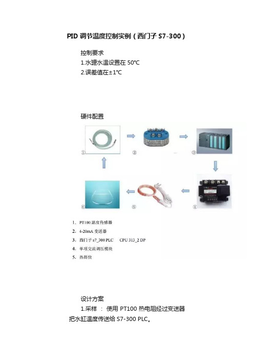
硬件配置
设计方案
1.采样:使用 PT100 热电阻经过变送器把水缸温度传送给S7-300 PLC。
2. 数据的处理:在S7-300 PLC 中经过PID 调节运算输出模拟量信号到功率调节器中。
3.温度调节:在功率调节器中把对应的模拟量转化为对应的功率来驱动热得快;
程序编写
1.创建名称为PID调节的工程,添加CPU314C-2DP.西门子CPU314C-2DP,自带有模拟量输入输出通道,无需扩展模块,在这里我们要注意他们的地址,以及输入输出的测量类型与测量范围。
这次试验用的是4-20mA 的变送器,输出我们采用0-10V电压输出,这些参数需要在硬件组态时进行设置,设置好以后注意编译保存下载。
2.程序的编写
3.PID调节
首先在开始菜单中打开PID调节面板,如下图所示:。
S7-300PID控制说明

S7-300的PID控制的方法1、这是一个典型的PID控制系统。
2、通过模拟量4--20mA的传感器来监视水池的液位,对应PLC的0-27648的工程值,经这个比例转换成水池的液位。
对应的液位是你液位传感器对应的最高量程。
这个值就是PID的反馈值。
3、阀门调节由量模拟量输出控制阀门调节开度,控制你水池的液位。
4、2、无法与实际水位对应(读的参数不知道表示什么意思)5、在PID调节中有不同的物理量,因此在参数设定中需将其规格化。
参数规格化:6、 1.规格化概念及方法:PID参数中重要的几个变量,给定值,反馈值和输出值都是用~之间的实数表示,因此,需要将模拟输入转换为~的数据,或将~的数据转换为模拟输出,这个过程称为规格化。
规格化的方法:(即变量相对所占整个值域范围内的百分比对应与27648数字量范围内的量)。
对于输入和反馈,执行:变量*100/27648,然后将结果传送到PV-IN和SP-INT,对于输出变量,执行:LMN*27648/100,然后将结果取整传送给PQW即可;7、 2.例:8、输入参数:9、SP_INT(给定值):0--100%的实数。
10、假定模块的输入变量量程为0-10Mpa,则SP_IN的范围对应0-10米.可以根据这一比例关系来设置给定值。
例:如给定米11、SP_INT(给定值)=(50%)12、PV_IN(过程值,即反馈值):0--100%的实数。
13、此值来自与阀门阀位(开度)的相应的压力反馈值。
其范围对应0-100%.即,当模拟量模板输入为数值为27648时则对应100%(量程的上限),数值为0时则对应0%(量程的下限)。
14、可以根据这一比例关系来换算PV_IN值。
例:如输入数值为12000时15、PV_IN(过程值,即反馈值)=12000/27648*=(%)16、输出参数:17、当通过PID控制器(FB41)运算后,即得出调节值LMN_PER,该值已转化范围为0-27648的整型数值。
西门子S7-300_400PLC的PID调节功能模块的详细说明
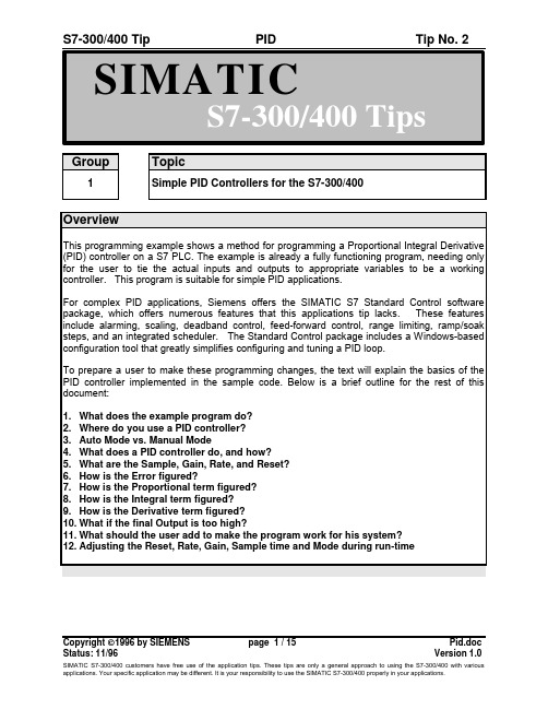
Group Topic1Simple PID Controllers for the S7-300/400OverviewThis programming example shows a method for programming a Proportional Integral Derivative (PID) controller on a S7 PLC. The example is already a fully functioning program, needing only for the user to tie the actual inputs and outputs to appropriate variables to be a working controller. This program is suitable for simple PID applications.For complex PID applications, Siemens offers the SIMATIC S7 Standard Control software package, which offers numerous features that this applications tip lacks. These features include alarming, scaling, deadband control, feed-forward control, range limiting, ramp/soak steps, and an integrated scheduler. The Standard Control package includes a Windows-based configuration tool that greatly simplifies configuring and tuning a PID loop.To prepare a user to make these programming changes, the text will explain the basics of the PID controller implemented in the sample code. Below is a brief outline for the rest of this document:1.What does the example program do?2.Where do you use a PID controller?3.Auto Mode vs. Manual Mode4.What does a PID controller do, and how?5.What are the Sample, Gain, Rate, and Reset?6.How is the Error figured?7.How is the Proportional term figured?8.How is the Integral term figured?9.How is the Derivative term figured?10.What if the final Output is too high?11.What should the user add to make the program work for his system?12.Adjusting the Reset, Rate, Gain, Sample time and Mode during run-timePID ExploredWhat does the example program do?示例程序的用途?This programming example is a skeleton program for a true PID controller and, as such, requires that the user make a few additions (i.e. read/write input/output variables) before it is fully functional. Before discussing these, however, let’s get a better feel for what a PID program actually does through a brief example.When do you use a PID controller?Figure 2.1 shows a picture of an example system to which a user might connect a PID controller. The figure shows a water tank sitting atop a hot plate, with a temperature control device for the hot plate and a small, monitored turbine for measuring the rate of the steam flow. This is a system that will work with a PID controller because of the relationship between the two variables: You can directly control the steam flow rate by adjusting the temperature of the hot plate. Figure 2.2 shows how both variables relate to the PID controller.The variable which represents the state of the system being controlled is called the ‘Process Variable.’ In our example above, you can see that the rate at which the steam spins the turbine is a good indicator of the event that we are trying to control: the speed at which the water is being boiled off. The output is the variable which, being altered by the controller, can affect the process variable by different degrees based on its intensity -- By turning the hot plate up, the water boils more quickly, more steam is produced, and the turbine’s speed increases. Therefore, when a variable that accurately reflects the state of the process and an adjustable control which proportionally affects the process variable, then it is possible to use a PID controller. Common systems using PID controllers are air conditioning systems, solution mixing, heaters, etc.Auto Mode vs. Manual Mode自动模式和手动模式There are two settings available on our PID controller. Putting a controller in Manual mode causes the PID loop do nothing, so that the user can directly control the output. The second, Auto, is the mode in which the PID loop is actually controlling the system. For the rest of this text, it will be assumed that the controller is in Auto mode.What does the PID controller do, and how does it do it? PID控制器作些什么?如何去做?Quite simply, a PID controller adjusts the value of its output to try and balance the value of the process variable to a given ‘setpoint.’To calculate the output value for a given instance, the controller finds the value of three different terms (using its user defined Sample time, Gain, Rate, and Reset values along with the calculated Error value): a Proportional term, an Integral term, and a Derivative term.Output = M P + M I + M DFormula 2.1What are the Sample, Gain, Rate, and Reset, and where do they come from?The sample rate is the cycle time (in milliseconds) at which the PID loop recalculates the output. The gain controls the sensitivity of the output calculation by affecting the influence of all the terms. The reset is a time given in milliseconds which is used to increase or decrease the influence of the Integral term in the equation. Finally, the rate value is used to control the influence of the Derivative term in the equation. Each of these values needs to be preset by the user before the PID controller starts.If the user does not want integral action (no I in the PID calculation), then a value of infinity or a value of 0 should be specified for the integral time. If the user does not want derivative action (no D in the PID calculation), then a value of 0 should be specified for the derivative time. If the user does not want proportional action (no P in the PID), then a value of 0 should be specified for the gain (gain is normally a multiplier in the integral and derivative coefficient calculation, but is removed from the coefficient calculation, if gain = 0, to allow I, ID, or D loop control).How is the Error figured? 误差是如何计算的?Error is figured as the difference between the normalized values of the setpoint and the process variable. The controller calculates this value in three steps. The first two steps are to change both the setpoint and the process variable into values that are based on a 0 to 1 (normalized) scale. This is done using the formulae:SP = raw_SP / max_valPV = raw_PV / max_valFormulae 2.2 & 2.3In the above formulae, the raw_SP and raw_PV values are the actual values that come into the controller, and the max_val term is the maximum value that either can take on. For example, ifthe values of raw_SP and raw_PV were being read in as values from 0 to 27,648, then the max_val term would have the value 27,648.After these two values have been calculated, the error term is figured as follows:Error = SP - PVFormula 2.4How is the Proportional term calculated?The proportional term, M P, is calculated using the following equation:M P = Gain * ErrorFormula 2.2Going back to our earlier example with the water tank, the proportional term says that as the speed of the turbine increases further above the setpoint, the heat is decreased proportionally to bring the speed down. As the turbine slows below the setpoint, the heat is increased to proportionally to bring the speed up.How is the Integral Term calculated? 积分项如何计算?The integral term, M I, is calculated using the following equation:M I = Bias + (C I * Error)Formula 2.3In this equation, two new terms are introduced. The first, C I, is the coefficient系数 of the Integral term, and is calculated from the Reset:C I = Gain * (Sample / Reset)Formula 2.4Both the Sample and Reset terms were introduced earlier, but in this equation their uses become apparent. The larger the Reset value is, the less impact the integral term will have onthe output, while larger Sample times give it a bigger influence (Sample time also affects the Derivative term, which will be explained later).The Bias term in Formula 2.3 represents (technically speaking) the area under the curve of a graph plotting the Error vs. time.Abstractly, however, the Bias value (ideally) grows to an output level that keeps the system stable, letting the Proportional and Derivative terms handle any small fluctuations. In relation to our water tank example from earlier, this means that eventually the Bias portion of M I would be the only significant contribution to the final output value, and the M P and M D terms would only be active (non-zero) when a fluctuation occurred.At a time n the equations for M I and the Bias term are:M I,n = Bias n-1 + (C I * Error)Bias n = M I,nFormula 2.5How is the Derivative term calculated?微分项如何计算?The derivative formula for a given time n is calculated with the following equation:M D = C D * (PV n-1 - PV n)Formula 2.6This formula only introduces 1 new term, C D, which is calculated using Formula 2.7.C D = Gain * (Rate / Sample)Formula 2.7The Sample term (which is also used in figuring C I) is the sample time from earlier. In the Derivative term, the Sample time is indirectly proportional to the derivative component, while the Rate is directly proportional.What if the final output value is too high?如果最终输出值太高怎么办?During many processes (such as the water tank example earlier), the Process variable doesn’t respond immediately to a change in the value of the output -- if the water in the tank were ice cold, then even an output of 100% is not going to cause an instantaneous increase in steam flow. Likewise, setting the output to 0% when the water is boiling doesn’t provide an immediate reduction in steam production.Because of this ‘system inertia,’ the output value for a give time could take on a value greater than 100% or less than 0%. In response to this, the PID program implements Output Clamping. If the output is greater than 100%, then it is clamped to 100%. If the output falls lower than 0%, then it is held to 0%.The only problem left to solve lies with the Bias portion of the Integral term. When the output for a system remains at 100% for a long period of time (such as when heating up cold water in our tank from earlier), the integral sum (which the Bias term represents) can grow to extremely large values. This means that when the variable starts responding, the Bias term will be keeping the calculated output well over 100% until it can be wound down. This generally results in the output swinging wildly from one limit to the other, but can be avoided using Bias Clamping. There are a few different types of Bias Clamping, but the only pertinent one here is the one used in the program. There are two different conditions which cause Bias clamping to occur and two formulae as well:If Output > 1Bias = 1 - (M P + M D)Formula 2.8If Output < 0Bias = -(M P + M D)Formula 2.9As the formulae show, when the Output grows to be greater than 1, the value of the Bias is adjusted so that the sum of M P, M D, and the Bias will be 1. Likewise, when the Output slips below 0, the value of the Bias is adjusted so that the above sum will be 0. The adjusted Bias value is then clamped such that its maximum value is 1 and its minimum value is 0.What should be added to make the program work for the system?1. Read in the Process Variable2. Write the Output3. Set the Setpoint4. Adjust the scale for the Input and Setpoint5. Adjust the scale for the Output6. Adjust the Reset, Rate, Gain, and Sample time values.Read in the Process VariableThe Process variable (the variable which accurately reflects the state of the system to be controlled) should be passed to the PV parameter of the function block.Write the OutputThe OUT parameter of the PID loop should be set to the analog output being controlled in the PID function block call.Set the SetpointThe user’s code must pass the Setpoint value to the PID function block via the SP parameter.Adjust the scale for the Process Variable and Setpoint 调整过程值和设定点值。
S7-300 PID用法

用西门子s7_300实现PID控制
在OB35中实现PID控制程序,OB35是一个以固定时间间隔循环执行的组织块,Hardware Config界面里可以设置间隔时间,而这也即是PID的采样时间。
应该注意设置的间隔值比OB35中程序运行时间长,否则会造成系统异常。
P:Kc 增大,系统余差减小,但不能消失.随着Kc 的增大,相应的过渡过程由不振荡变为临界振荡或衰减振荡.
I:积分作用能消除余差.Ti 小表示积分作用强,积分作用越强,过渡过程的振荡越剧烈. D:在比例作用的基础上增加微分作用将使系统的过度过程的振荡程度降低,提高了系统的稳定性.但微分作用不能太强.即Td 不能太大.否则会因反应速度太快引起系统剧烈振荡。
第30讲 基于S7-300的PID液位控制系统
UNSCALE功能使用以下等式:
OUT = (IN-HO_LIM)/(HI_LIM-HO_LIM)* (K2-K1) ]+ K1,
并根据输入值是BIPOLAR还是UNIPOLAR设置常数K1和K2。 BIPOLAR:假定输出整型值介于-27648和27648之间,因
此,K1 = -27648.0,K2 = +27648.0
100%);
PV_FAC: REAL:过程变量比例因子 PV_OFF: REAL:过程变量偏置值(OFFSET)
LMN_FAC: REAL:PID输出值比例因子;
LMN_OFF: REAL:PID输出值偏置值(OFFSET); I_ITLVAL:REAL:PID的积分初值;有I-ITL-ON选择有效; DISV :REAL:允许的扰动量,前馈控制加入,一般不设置;
设定水箱水位值为100mm时,则不管水箱的出水量如何,调节进水量, 都要求水箱水位能保持在100mm位置,如出水量少,则要控制进水量 也少,如出水量大,则要控制进水量也大。
二、控制思路
因为液位高度与水箱底部的水压成正比,故可用一个压力传感 器来检测水箱底部压力,从而确定液位高度。要控制水位恒定,需 用PID算法对水位进行自动调节。把压力传感器检测到的水位信号4 ~20mA送入至S7-300 PLC中,在PLC中对设定值与检测值的偏差 进行PID运算,运算结果输出去调节水泵电机的转速,从而调节进水 量。 水泵电机的转速可由变频器来进行调速。
2、PLC输入输出信号接线图
五、程序用到的FC与FB
1、FC105
SCALE功能接受一个整型值(IN),并将其转换为以工程单 位表示的介于下限和上限(LO_LIM和HI_LIM)之间的实型值。将 结果写入OUT。
PID控制在S7-300(PLC)系统中的应用
PID控制在S7-300(PLC)系统中的应用一、引言自动控制系统可分为开环控制系统和闭环控制系统。
一个自动控制系统通常包括控制器﹑检测机构﹑执行机构三个主要组成部分。
如果系统控制器的输出能够根据被控对象(检测机构的检测结果)自动作出调整,或者说,被控对象能够实时地影响控制器的输出,并且使得被控对象尽量保持某个稳定的状态,那么,我们可以说这是一个闭环控制系统。
闭环控制系统的例子很多,比如,自来水在城市管网中的水压控制,水压过高,将会导致管网的损坏,反之,则会影响到高层居民的生活供水。
在这个系统中,检测机构是智能压力变送器;执行机构是水泵及驱动水泵电机的变频器;控制器通常采用PID控制器,这个PID控制器可以是包含在变频器的处理器中,也可以是包含在一套PLC中。
笔者结合多年的西门子PLC工程实践经验,谈谈有关PID在S7-300中的应用,以作抛砖引玉。
二、编写自己的功能块在西门子PLC编程软件STEP7中,为用户提供了多个PID控制功能块。
在梯形图编辑状态(LAD/STL/FBD),打开“视图→总览(View→Overviews)”,可以找到“库→标准库→PID控制块(Libraries→Standard Library→PID Control Blocks)”。
其中连续PID控制块FB41比较常用,但是,它的接口部分参数繁多(有44个),对参数的注释较少,实际使用过程中很不方便,调试也比较困难;还有一点,它是由高级语言SCL 编译的,因为没有源程序,对它作任何的修改都是难以想象的事情。
在实践中,笔者使用自己编写的PID控制块,为特定的场合定制,小巧灵活,调试十分方便,效果也比较理想。
根据PID控制的原理,我们采用了下述简化的计算公式:△outPID = △outP + △outI +△outD (1)△outP = uP * (MEAS - LastM) (2)△outI = uI * (MEAS - DestV) (3)△outD = uD * ((MEAS - LastM) - (LastM - LLastM)) (4)CurrOUT = LastOUT ±△outPID (5)上述公式的说明:(1)式中,△outPID为本次PID调节的总量,△outP、△outI、△outD则分别为比例、积分、微分的调节分量;(2)式中,uP 为比例系数,MEAS 表示当前测量值,LastM表示上一次的测量值;(3)式中,uI 为积分系数,DestV表示设定的目标值;(4)式中,uD 为微分系数,LLastM表示上上一次的测量值;(5)式中,CurrOUT 表示当前输出值,LastOUT表示上一次输出值,式中用了“±”符号,当输出量增加时,使检测值也增加时,采用“-”号,反之,采用“+”号。
S7-300_PID参数说明
BOOL BOOL BOOL BOOL
FALSE / TRUE FALSE / TRUE FALSE / TRUE FALSE / TRUE FALSE / TRUE >=1ms -100.0 to +100.0(%) or phys.value 1 -100.0 to +100.0(%) or phys.value 1
MAN GAIN TI TD TM_LAG DEADB_W
in in in in in in
手动值 增益 积分时间 微分时间 微分延时 死区
REAL REAL TIME TIME TIME REAL
0.0 2
DB*.DBD16.0 DB*.DBD20.0 DB*.DBD24.0 DB*.DBD28.0 DB*.DBD32.0 DB*.DB0.1
PVPER_ON
in
过程变量输入开关 BOOL
FALSE / TRUE
FALSE
DB*.DBD0.2
P_SEL I_SEL INT_HOLD I_ITL_ON D_SEL CYCLE SP_INT
in in in in in in in
比例作用开关 积分作用开关
TRUE TRUE FALSE FALSE FALSE T#1S 0.0
DB*.DBD0.3 DB*.DBD0.4 DB*.DBD0.5 DB*.DBD0.6
微分作用开关 循环时间 设定值
BOOL TIME REAL
D_SEL=1微分作用启动。 D_SEL=0微分作用停止。
DB*.DBD0.7 DB*.DBD2.0 DB*.DBD6.0
DB*.DBD44.0 DB*.DBD48.0 DB*.DBD52.0 DB*.DBD56.0 DB*.DBD60.0 DB*.DBD64.0 DB*.DBD68.0 DB*.DBD72.0 DB*.DBD76.0 DB*.DBD78.0 DB*.DBD78.1 DB*.DBD80.0 DB*.DBD84.0 DB*.DBD88.0 DB*.DBD92.0 DB*.DBD96.0
S7-300的PID控制
。了以可就用调会要需只�题问些这等等算运分微、算运分积、算运例
现实来 14BF 用使何如�表仪规常替代来 14BF 的 CLP003-7S 用使是就的做要们我天今
、度例比�即。数参 D、I、P 定设够能该应就器制控 DIP 是然既�器制控的里表仪规常们我于 当相就 14BF�制控 DIP 现实来 14BF 块模用使以可们我�CLP003-7S 子门西习学过经
制控 DIP 现实 14BF 用使
示所图下如 在接直以可此因 。口端的 14BF 到看以可里 53BO 在以所的 14BF 用调里 53BO 在是们我 。数参设接直上口端些这
这用调去间时段一隔每要需只们我�的算运 DIP 现实来用是它�序程子个一于当相 14BF
可率频的用调�了以可就 14BF 用调里 53BO 在们我以所。制控 DIP 现实以可就”序程子“一
景背要还么什为�数参赋口端 14BF 给接直以可面里 53BO 在以可然既�问会人有里这到
���呢 BD 块据数
下看观你迎欢,用使何如讲们我节一下�了识认的本基个一了有 14BF 对经已们我节一这过经
。节一
。等钮按换切动自/动手有又�数参 DIP 改更以可上板面的表仪规常。间时分微、间时分积
。理管与制控中集们我于便不且而�高常非得变会就本成制控 DIP 的路多实现要果如�制控 DIP 的路一现实能只就器制控个一里表仪规常而�制控 DIP 到用要常常中域领化动自在
。定设上口端的 14BF 在就数参的变改常经要。定设面里 BD 在接直就们我 �的变改常经要需不数参些有�数参设方地个两在时同以可们我�点缺优的法方种两合结 。了以只就 量变的应相变改要需只数参变改要需们我当�数参有存面里量变�量变个一是数参赋口端给 。了数参的面里表据数改更能不就后之 CLP 到载下 序程当以所 �量变个一是能不�值定固个一是能只数参面里表据数在�数参置设方地个两在以可们我以所 有果如 �数参设口端的 14BF 给里 53BO 在有没有户用 �查检先会中程过行运在 CLP 实其 。数参取去面里表据数景背到就有没果如�数参的上口端用使接直就。置设面 Nhomakorabea性属在以
用S7-300PLC进行PID控制——功能块FB41的功能及用法介绍
用S7-300PLC进行PID控制——功能块FB41的功能及用法介绍一、控制系统假设图1 液压系统控制框图如图1为液压系统的简单控制框图。
控制方式为使用变频器拖动泵,使系统的实际压力等于设定压力。
本文基于此系统,探讨一下如何用S7-300进行PID控制。
为方便讨论,做以下假定:•· 系统压力的可调范围为:0 – 1MPa;•· 变频器的变频范围为:0 – 50Hz;•· 压力传感器的输入外设地址:PIW272;模拟量输出外设地址为PQW288。
二、FB41简介在STEP7中的库中,有专门用于PID控制的FB块——FB41。
PID控制必须在循环中断中执行,以确保其扫描、执行时间基本固定。
本例中的CPU仅有OB35一个循环中断,因此,要在OB35中调用FB41。
图2 FB41在库中的位置图3 FB41的逻辑图FB41的逻辑如图3所示。
分解介绍如下:•· SP_INT端为给定值,本例中即为给定压力,假设为0.5MPa;即:0.5==>'SP_INT';•· 实际值有两条通路可选:· 当PVPER_ON=0时,PV_IN端的值为实际值,该值通常有FC105转换而来;· 当PVPER_ON=1时,PV_PER端的值为实际的压力值,该值来自AI模块,为压力传感器的反馈值;本例中,我们以PVPER_ON=1时,来说明。
即:1==>'PVPER_ON'、PIW272==>'PV_PER'•· PV_FAC、PV_OFF对应压力的范围,即:1==>'PV_FAC'、0==>'PV_OFF'。
•· PV是根据PV_PER计算出的实际压力值。
具体来说:PV_PER=0时,对应的实际压力为PV_OFF,即0MPa;PV_PER=27648时,对应的实际压力为PV_FAC,即1MPa;PV=PV_PER/27648*(PV_FAC –PV_OFF),本例中,PV=PV_PER/27648;•· ER为给定值SP_INT和实际值PV的偏差,PID即是基于它进行调节的;•· GAIN、TI、TD分别为比例、积分、微分的系数。
S7-300-PID-使用说明及应用
定时中断组织块OB35西门子S7-300/400有9个定时中断组织块:OB30、OB31、OB32、OB33、OB34、OB35、OB36、OB37、OB38 。
CPU可以定时中断去执行这些模块中的程序,即:每隔一段时间就停止当前的程序,转去执行定时中断组织块中的程序,执行结速后再返回。
相当于单片机的定时中断。
这9个组织块功能相同,你可以选择其中之一使用,区别是它们的中断优先级不同,如果程序中用到了多个定时中断组织块,应设好它们的执行优先级。
S7-300CPU 可用的定时中断组织模块是OB35,在300站点的硬件组态中,打开CPU 属性设置可以看到其它的中断组织块为灰色。
OB35默认的调用时间间隔为100ms 我们可以根据需要更改,定时范围是1-60000毫秒(ms)设置中断时间间隔如下图所示注意:设置的时间必须大于OB35中程序执行所花费的时间。
例如:如果中断时间间隔为50ms而OB35中的程序花费的时间是70ms,那么OB35中的程序还没执行完毕就产生第二次中断,程序就会出错,这显然是我们不想看到的结果。
以现在的技术,让你间隔一小时去月球拿一块石头你能做到吗???去月球所用的时间大于去月球的时间间隔,你做不到吧???正确设置:中断时间间隔大于OB35中程序执行完毕一次所需的时间使用FB41实现PID控制在自动化领域中常常要用到PID控制,而常规仪表里一个控制器就只能实现一路的PID 控制,如果要现实多路的PID控制成本就会变得非常高,而且不便于我们集中控制与管理。
经过学习西门子S7-300PLC,我们可以使用模块FB41来实现PID控制,FB41就相当于我们常规仪表里的控制器,既然是PID控制器就应该能够设定P、I、D参数。
即:比例度、积分时间、微分时间。
常规仪表的面板上可以更改PID参数,又有手动/自动切换按钮等。
今天我们要做的就是使用S7-300PLC 的FB41来代替常规仪表,如何使用FB41来实现PID控制的呢??FB41是一个功能块,它所能实现的功能(PID)已经由专业人员设计好,我们只要调用它,并根据我们的需要来更改相应的参数即可使用。
- 1、下载文档前请自行甄别文档内容的完整性,平台不提供额外的编辑、内容补充、找答案等附加服务。
- 2、"仅部分预览"的文档,不可在线预览部分如存在完整性等问题,可反馈申请退款(可完整预览的文档不适用该条件!)。
- 3、如文档侵犯您的权益,请联系客服反馈,我们会尽快为您处理(人工客服工作时间:9:00-18:30)。
S7-300的PID控制的方法
1、这是一个典型的PID控制系统。
通过模拟量4--20mA的传感器来监视水池的液位,对应PLC的0-27648的工程值,经这个比例转换成水池的液位。
对应的液位是你液位传感器对应的最高量程。
这个值就是PID的反馈值。
阀门调节由量模拟量输出控制阀门调节开度,控制你水池的液位。
2、无法与实际水位对应(读的参数不知道表示什么意思)?
在PID调节中有不同的物理量,因此在参数设定中需将其规格化。
参数规格化:
1.规格化概念及方法:PID参数中重要的几个变量,给定值,
反馈值和输出值都是用0.0~1.0之间的实数表示,因此,需要将模拟输入转换为0.0~1.0的数据,或将0.0~1.0的数据转换为模拟输出,这个过程称为规格化。
规格化的方法:(即变量相对所占整个值域范围内的百分比对应与27648数字量范围内的量)。
对于输入和反馈,执行:变量*100/27648,然后将结果传送到PV-IN和SP-INT,对于输出变量,执行:LMN*27648/100,然后将结果取整传送给PQW即可;
2.例:
输入参数:
SP_INT(给定值):0--100%的实数。
假定模块的输入变量量程为0-10Mpa,则SP_IN的范围0.0-1.00
对应0-10米.可以根据这一比例关系来设置给定值。
例:如给定5.0米
SP_INT(给定值)=5.0/(10.0-0.0)*100.0=50.0(50%)
PV_IN(过程值,即反馈值):0--100%的实数。
此值来自与阀门阀位(开度)的相应的压力反馈值。
其范围0.0-1.0对应0-100%.即,当模拟量模板输入为数值为27648时则对应100%(量程的上限),数值为0时则对应0%(量程的下限)。
可以根据这一比例关系来换算PV_IN值。
例:如输入数值为12000时
PV_IN(过程值,即反馈值)=12000/27648*100.0=43.403(43.403%)
输出参数:
当通过PID控制器(FB41)运算后,即得出调节值LMN_PER,该值已转化范围为0-27648的整型数值。
例如经运算为43.403%,
LMN_PER=43.403*27648/100,取整后为12000,将LMN_PER 送入模拟量输出模板即可.
3、积分时间不知道该如何设定?
(1)对于比例控制来说,将比例度调到比较大的位置,逐步减小以得到满意的曲线。
(2)对于比例积分来说,先将积分时间无限大,按纯比例作用
正定比例度。
得到满意曲线后,将比例度放大(10~20)%,将积分时间由大到小加入,直到获得满意曲线。
PID控制器参数的工程整定,各种调节系统中P.I.D参数经验数据以下可参照:
液位L: P=20~80%,T=60~300s;
4、应用实例,连接:
基于PLC的闭环控制系统PID控制器的实现:。