三菱定位模块QD75参数信号地址表(无密码)
三菱PLC的QD75M系列-使用教程

新一代高速定位模块—QD75M详介目录1.QD75M的特性2.QD75M的规格和性能3:参数设定4:定位数据编写5.GX-Configurator-QP 的说明6.应用指令介绍7.QD75M附加功能的说明8.应用例子1.1 QD75M的特点有1、2、4轴的模块可选,每个模块占用32个I\O点采用SSCNET的高速总线连接servo,速度10Mpps多种定位方式每个轴可编写600个基本定位数据,还有5组每组50个高级定位数据。
有35种控制方式,有速度控制、固定值进给控制、差补控制等。
高可靠性和可维护性,和SERVO之间通过总线连接,可靠性高、易于维护。
和高分辨率的电机配合使用,轻松构建绝对位置系统。
通过GX-Configurator-QP实现参数设置、定位数据编写、监控和测试。
注:SSCNET:SERVO System Control NETwork1.2 系统的硬件连线图扩展电缆主基板CPU模块I\O模块定位模块扩展系统USB电缆RS232电缆SSCNET电缆电缆外围设备个人电脑手动脉冲发生器外部信号输入•前后极限信号•外部命令信号•切换信号•停止信号•原点信号1.3 定位原理说明读写操作定位命令控制命令监控数据接口定位控制速度控制电流控制转换器电流反馈速度反馈位置反馈接口手动脉冲发生器外部信号输入•前后极限信号•外部命令信号•切换信号•停止信号•原点信号2.1 模块的I/O信号列表Device NO.Signal name commentX0QD75 READY在接到PLC READY信号信号后,检查参数设置,如果无误,该信号为ONX1同步标志在PLC ON,如果CPU能够访问QD75,该信号为ONX4~ X7分别为各轴的M代码ON信号表明有效的M代码已经存在相应的寄存器中,可以读取了X8~XB各轴的错误诊断当轴发生错误时,相应的诊断信号为ONXC~XFBUSY 信号当轴在运动状态时,该轴对应的BUSY信号为ONX10~ X13启动完成当定位启动信号为ON,并且QD75启动定位处理时该信号为ONX14~ X17定位完成在轴执行定位操作的过程中该信号一直为ON1.定位模块的状态信号——表明定位模块的状态(QD75 PLC)2.1 模块的I/O信号列表Device NO.Signal name commentY0PLC READY该信号通告QD75,PLC准备好Y1全部轴SERVO ON全部轴的SERVO准备操作Y4~Y7各轴的停止信号当该信号为ON,对应轴的所有操作都不执行Y8 Y9~ YA YB~ YC YD~ YE YF~各轴的手动正反转启动信号当信号为ON时,对应的轴已指定的手动速度运行Y10~Y13定位启动启动定位运行或OPR操作Y14~ Y17执行禁止标志当该信号为ON时,不能执行定位操作2.PLC的指令信号(PLC QD75)2.2 主要缓冲区说明项目轴1轴2轴3轴4注释MD20 当前进给值8008019009011000100111001101存储当前命令的地址(可用命令更改)MD21机器进给值8028039029031002100311021103存储符合机器坐标的当前位置的地址(建立完坐标系之后,不可更改)MD23轴出错编号80690610061106当监测到轴出错后,存储出错的代码MD25有效M代码80890810081108存储当前有效的M代码Cd3定位启动编号1500160017001800定位启动编号Cd4定位启动点编号1501160117011801定位启动点编号(用于块启动数据)2.3 运行方式介绍定位完成P1连续定位控制P1P2连续轨迹控制P1P2定位完成:单步执行连续定位控制:执行完一个定位数据后,执行下一个定位数据(速度要降为0)连续轨距控制:执行完一个定位数据后,执行下一个定位数据(速度不降为0)2.4 控制方式介绍➢1/2/3/4轴的直线控制(包括直线插补)➢1/2/3/4轴的固定进给控制➢2轴圆弧插补控制➢1/2/3/4轴的速度控制➢V/P 和P/V 转换控制➢当前值变更➢跳转指令辅助点方式圆心+正反转方式2.5 高级定位功能介绍正常启动-启动要执行的基本定位数据条件启动-条件满足,执行基本定位数据等待启动-等待条件满足,执行基本定位数据同时启动-同时启动其他轴的定位数据条件循环启动-条件满足,就执行循环操作无条件循环启动-设定循环的次数3. 参数列表参数定位参数基本参数1基本参数2具体参数1调整参数OPR参数OPR基本参数OPR具体参数SERVO 参数基本参数具体参数1具体参数2具体参数2当启动系统时按照设备和适用电动机设置当启动系统时按照系统配置设置设置执行OPR所需的参数值根据使用的SERVO具体设置3.1 基本参数项目设定范围默认值说明单位设定(Pr.1)0:mm 1:inch2:degree 3:pls3:pls根据系统用户自己选择每转的脉冲数(AP)(Pr.2)1-20000000002000电子齿轮功能(参见P.31)每转的进给量(AL)(Pr.3)根据Pr.1参数设定范围不同2000单位放大倍(AM)(Pr.4)1: 1 times10:10 times100:100 times1000:1000 times1:1 times速度极限值(Pr.8)根据Pr.1参数设定范围不同200000对定位和OPR操作都有效加速时间0(Pr.9)1-8388608ms1000从零到速度极限值(Pr.8)的时间减速时间0(Pr.10)1-8388608ms10003.2 具体参数1项目设定范围默认值说明反向间隙补偿量(Pr.11)根据Pr.1参数设定范围不同0可以补偿齿轮传动时由反向间隙引起的误差软件行程极限上限值(Pr.12)根据Pr.1参数设定范围不同2147483647可以通过软件防止超程,还必须在范围之外附近安装限位开关软件行程极限下限值(Pr.13)-2147483648软件行程极限选择(Pr.14)0,100-当前进给值1-机器进给值软件行程极限有效\无效设置(Pr.15)0,100-在手动和脉冲发生器运行时有效1-在手动和脉冲发生器运行时无效命令到位宽度(Pr.16)根据Pr.1参数设定100设置使命令到位变成ON的剩余距离转矩极限设置值(Pr.17)1~500%300设置伺服电机产生的最大转矩M代码ON输出时间(Pr.18)0,100-定位启动时输出M代码1-定位完成输出M代码3.2 具体参数1项目设定范围默认值说明速度切换模式(Pr.19)0,100-标准切换,在执行下一个定位数据时切换速度1-前加载模式,执行完当前定位数据时切换速度插补速度指定(Pr.20)0,100-合成速度1-参考轴速度速度控制期间的当前进给值(Pr.21)0,1,200-禁止当前值更新1-允许当前值更新2-当前值清零输入信号逻辑选择(Pr.22)0-逻辑负1-逻辑正0要和外围连接一致脉冲发生器输入选择(Pr.23)0,1,2,300-AB相乘4 1-AB相乘22-AB相乘1 3-PLS/SIGN 模式速度-位置功能选择(Pr.200)0-INC2-ABS0选择速度位置切换控制的模式,如果设置成0,2以外的数,则以INC模式进行3.3 具体参数2项目设定范围默认说明值1-83886081000加速时间1,2,3(Pr.25~Pr.27)减速时间1,2,3(Pr.28~Pr.30)20000要小于Pr.8的速度极限值手动速度极限值(Pr.31)根据Pr.1参数设定范围不同手动加速时间选择(Pr.32)0,1,2,30选择0~3中的其中一组用于手动运行的加/减速时间手动减速时间选择(Pr.33)加速/减速处理选择(Pr.34)0,100-自动梯形加减速1-S型加减处理S型比率(Pr.35)1~100%100S型曲线表示使用正弦曲线绘制加减速曲线的地方突然减速停止时间(Pr.36)1-83886081000设置突然停止情况下从速度极限值到零速的时间3.3 具体参数2项目设定范围默认值说明停止组1~3突然停止选择(Pr.37~Pr.39)0-正常停止1-突然停止0组1-用硬件行程开关组2-I/O复位,PLC READY信号OFF,测试模式故障组3-外围停止信号定位完成信号输出时间(Pr.40)0~65535300设置定位完成信号x4 x5 x6 x7的输出时间容许环形插补出错宽度(Pr.41)根据Pr.1设定100设置计算的弧形路径和终点地址的容许出错范围外部命令选择(Pr.42)0,1,2,300-外部定位启动1-外部变速请求2-速度-位置位置-速度切换请求3-跳跃请求Servo重新启动的允许范围(Pr.201)0,1~163840PLS00-表示不可重新启动1~163840设定容许的范围3.4 OPR基本参数项目设定范围默认值说明OPR方式(Pr43)0,4,5,600-近点狗方式4-计数方式15-计数方式2 6-数据设置方式OPR的方向(Pr.44)0,100-正向(地址增量方向)1-负向(地址减量方向)OPR的地址(Pr.45)根据Pr.1设定0当完成原点回归时,停止位置的地址OPR速度(Pr.46)1OPR的启动速度OPR蠕动速度(Pr.47)1近点狗ON后的速度OPR重试功能(Pr.48)0,100-不要用限位开关重试OPR1-要用限位开关重试OPR3.4 OPR具体参数项目设定范围默认值说明近点狗ON后的位移量设置(Pr.50)根据Pr.1设定0使用计数方式1,2时,设定近点狗ON到OP的位移量OPR加速时间选择(Pr.51)0,1,2,30设定OPR时,使用那组加速、减速时间OPR减速时间选择(Pr.52)OP移动量(Pr.53)根据Pr.1设定0从OP停止的位置移动的量OP转矩限制(Pr.54)1-300%300设置在OPR期间,达到蠕动速度后限制电机转矩的值OP移动期间速度指定(Pr.56)0,100-OPR速度1-蠕动速度OPR重试期间的停顿时间0~6553503.5 SERVO参数-基本参数➢(Pr.100~Pr.107)—主要包括描述SV&motor的系列型号等基本信息➢Pr.108—自动调谐功能0-插补模式1-自动调节方式12-手动调节方式23-自动调节方式24-手动调节方式1➢Pr.109—servo 的响应速度3.5 SERVO参数SERVO 调整参数(Pr.112~Pr.126)—包括负载的惯量及其速度位置环的增益等。
QD75定位模块
軸1:1500 軸2:1600 軸3︰1700 軸4:1800
程 式 起 動﹝1﹞
〔ZP.PSTRT1 〝Un〞 (S) (D)〕
〝Un〞:QD75 I/O槽位,入出力番號 (S):控制指令暫存器存放位置 (D):命令完了ON一次;異常完了(D+1)ON
(S)+ 0:系統區域 (S)+ 1:完了情況〔0:正常終了;0以外:異常完了〕 (S)+ 2:起動番號》定位番號:1 ~ 600
*產品分類
每個模塊的軸數方面,1個軸、2個軸和4個軸類型的產品可用
QD75P1/QD75D1:1個軸
QD75P2/QD75D2:2個軸
QD75P4/QD75D4:4個軸
應用
§快速起動 在CPU模塊給QD75發出起動命令後,QD75可以以6 ~ 7ms 的速度快速起動,減少了機械應答時間。
§補間 可以執行2、3或4軸線性補間控制和2軸圓弧補間控制。
PC CPU 系 統
*PC CPU模塊能夠通過C語言或BASIC語言進行I/O控制 和智能功能模塊控制。
§用QCPU配置多PLC系統時,可 以通過QCPU與PC CPU的組合 實規快速、高度靈活的系統。 由於前者的CPU改變機械控制, 而後者的CPU改變數據通訊和大 容量處理,所以順序控制可以與 PC應用程序集成在一起。
§控制系統 控制系統選擇範圍很廣,諸如點到點控制、固定進給控制 、速度控制、速度/位置切換控制和位置/速度切換控制。
公用功能
*參數初始化功能
QD75的緩沖暫存器和快閃 ROM中的資料恢復到工廠設置值。 下面兩種方法可用:1)使用順控程序 2)使用GX Configurator-QP
*執行資料備份功能
特性
三菱QD75系列地址表
470 471 472 473 474 475 476 477 478 479 480 481 482
109页
double word word word double word
111页
word word word word word
113页
word word word
184 186 187 188 189
加速时间 1000 减速时间 减速时间 减速时间 JOG 速度极限值 JOG 运行加速时间选择 JOG 运行减速时间选择 加速/减速处理选择 S 形比例 突然停止减速时间 停止组 1 突然停止选择 停止组 2 突然停止选择 停止组 3 突然停止选择 定位完成信号输出时间 容许环形插补出错宽度 300 100 0 20000 0 0 0 100 1000
340 341 342 343 344 345 346 347 348 349 350 351 352 353 354 355 356 357 358 359 360 361
490 491 492 493 494 495 496 497 498 499 500 501 502 503 504 505 506 507 508 509 510 511 123页 117页
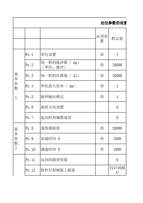
定位参数的设置项目 必须设 置
默认值
Pr.1 Pr.2 基 本 参 数 1 Pr.3 Pr.4 Pr.5 Pr.6 Pr.7 基 本 参 数 2 Pr.8 Pr.9 Pr.10 Pr.11 Pr.12
单位设置 每一转的脉冲数( Ap) (单位:脉冲) 每一转的位移量( Al) 单位放大倍率( Am) 脉冲输出模式 旋转方向设置 起动时的偏置速度 速度极限值 加速时间 0 减速时间 0 反向间隙补偿量 软件行程极限上限值
三菱PLC的QD75M系列-使用教程

项目
设定范围
单位设定(Pr.1)
每转的脉冲数(AP) (Pr.2)
每转的进给量(AL) (Pr.3)
单位放大倍(AM) (Pr.4)
0:mm
1:inch
2:degree 3:pls
1-2000000000
根据Pr.1参数设定 范围不同
1: 10: 100: 1000:
1 times 10 times 100 times 1000 times
4.1 基本定位数据编写
定位地址——表示要运行到的地址 圆弧地址——在圆弧插补时用到,如果选择的是辅助 点圆弧插补方式,该值是辅助点的值;如果选择的是 圆心定位方式,该值是圆心的值 命令速度——根据参数,表示合成速度或长轴速度 等待时间——当执行过该定位数据后的停留时间 M代码——输出M代码,完成辅助工作
从零到速度极限值(Pr.8)的时间
3.2 具体参数1
项目
设定范围
反向间隙补偿量 (Pr.11)
根据Pr.1参数设定 范围不同
软件行程极限上限值 (Pr.12)
软件行程极限下限值 (Pr.13)
根据Pr.1参数设定 范围不同
软件行程极限选择 0,1 (Pr.14)
软件行程极限有效\
0,1
无效设置(Pr.15)
速度极限值(Pr.8) 加速时间0(Pr.9)
根据Pr.1参数设定 范围不同
1-8388608ms
减速时间0(Pr.10)
1-8388608ms
默认值 3:pls 2000 2000 1:1 times
说明 根据系统用户自己选择
电子齿轮功能 (参见P.31)
200000
对定位和OPR操作都有效
1000 1000
QD75参数设置说明

QD75参数设置说明---程明基本參數11、单位设置紅色需設定,藍色未默認值,紫色疑问。
不同的单位(毫米、英寸、度和脉冲)适用于不同的系统:毫米或英寸....X-Y 工作台、传送带(依据机器规格选择毫米或英寸。
)度................... 旋转体(360 度/旋转)脉冲...............X-Y 工作台、传送带当你更改单位时,注意其它参数和数据的值不会自动变化。
在更改单位后,检查参数和数据值是否在容许范围之内。
设置以“度”为单位来执行速度-位置切换控制(ABS 模式)。
2、每一转的脉冲数(Ap)设置电动机轴完成旋转需要的脉冲数。
如果你使用Mitsubishi 伺服放大器MR-H、MR-J2/J2S 或MR-C,则应按速度/位置检测器规格中给出的“伺服电动机每一转的分辨率”设置每一转的脉冲数。
每一转的脉冲数(Ap)=伺服电动机每一转的分辨率=编码器脉冲数(脉冲 / 转)3、每一转的位移量(Al)电动机每转对应的工件的位移量由机械结构确定。
如果蜗轮导程(毫米/转)是PB 并且减速比是1/n,那么:每一转的位移量(AL)= PB × 1/n4、单位放大倍率(Am)单位放大倍率(Am)是值1、10、100 或1000。
如果“PB × 1/n”值超过μm,则用单位放大倍率调节,使“每一转的位移量(Al)”不超过μm(QD75D,QD75P)。
例子:当每一转的位移量(AL)= PB × 1/n = μm(= 60mm)时每一转的位移量(AL)= 每一转的位移量(Al)×单位放大倍率(Am)= 6000 × 10= 600 × 1005、脉冲输出模式(QD75D,QD75P專有)要点“脉冲输出模式”的唯一有效值是在接通电源或复位PLC CPU 后第一时间PLC READY 信号 [Y0] 从OFF 变成ON 时的值。
一旦 PLC READY 信号 [Y0] 变成了ON,就不会复位值,即使把另外的值设置成参数并且PLC READY 信号 [Y0] 从OFF 变成ON。
QD75MH控制地址
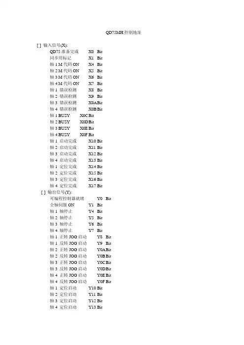
QD75MH控制地址[-] 输入信号(X):QD75准备完成 -- X0 Bit同步用标记-- X1 Bit轴1 M代码ON -- X4 Bit轴2 M代码ON -- X5 Bit轴3 M代码ON -- X6 Bit轴4 M代码ON -- X7 Bit轴1 错误检测-- X8 Bit轴2 错误检测-- X9 Bit轴3 错误检测-- X0A B it轴4 错误检测-- X0B Bit轴1 BUSY -- X0C Bit轴2 BUSY -- X0D B it轴3 BUSY -- X0E Bit轴4 BUSY -- X0F Bit轴1 启动完成-- X10 Bit轴2 启动完成-- X11 Bit轴3 启动完成-- X12 Bit轴4 启动完成-- X13 Bit轴1 定位完成-- X14 Bit轴2 定位完成-- X15 Bit轴3 定位完成-- X16 Bit轴4 定位完成-- X17 Bit[-] 输出信号(Y):可编程控制器就绪-- Y0 Bit全轴伺服ON -- Y1 Bit轴1 轴停止-- Y4 Bit轴2 轴停止-- Y5 Bit轴3 轴停止-- Y6 Bit轴4 轴停止-- Y7 Bit轴1 正转JOG启动-- Y8 Bit轴1 反转JOG启动-- Y9 Bit轴2 正转JOG启动-- Y0A B it轴2 反转JOG启动-- Y0B Bit轴3 正转JOG启动-- Y0C Bit轴3 反转JOG启动-- Y0D B it轴4 正转JOG启动-- Y0E Bit轴4 反转JOG启动-- Y0F Bit轴1 定位启动-- Y10 Bit轴2 定位启动-- Y11 Bit轴3 定位启动-- Y12 Bit轴4 定位启动-- Y13 Bit轴1 执行禁止标记-- Y14 Bit轴2 执行禁止标记-- Y15 Bit轴3 执行禁止标记-- Y16 Bit轴4 执行禁止标记-- Y17 Bit[-] 缓冲存储器监视[-] 监视数据[-] 系统监视数据测试监视中标记-- U0\G1200 字[无符号]启动履历... 详细对话框错误履历... 详细对话框报警履历... 详细对话框Flash ROM写入次数-- U0\G1424 双字[无符号]紧急停止输入-- U0\G1431 字[无符号][-] 轴监视数据轴1 进给当前值-- U0\G800 Double Word[Signed]轴1 进给机械值-- U0\G802 Double Word[Signed]轴1 进给速度-- U0\G804 双字[无符号]轴1 轴错误编号... -- U0\G806 错误代码轴1 轴报警编号... -- U0\G807 报警代码轴1 有效M代码 -- U0\G808 字[无符号]轴1 轴动作状态-- U0\G809 字[无符号]轴1 计数速度-- U0\G810 双字[无符号]轴1 轴进给速度-- U0\G812 双字[无符号]轴1 速度·位置切换控制的定位量-- U0\G814 Double Word[Signed]轴1 外部输入输出信号下限值 -- U0\G816.0 Bit轴1 外部输入输出信号上限值 -- U0\G816.1 Bit轴1 外部输入输出信号停止信号-- U0\G816.3 Bit轴1 外部输入输出信号外部指令信号/切换信号-- U0\G816.4 Bit轴1 外部输入输出信号近点DOG信号-- U0\G816.6 Bit轴1 状态速度控制中标记 -- U0\G817.0 Bit轴1 状态速度·位置切换锁存标记 -- U0\G817.1 Bit轴1 状态指令到位标记-- U0\G817.2 Bit轴1 状态原点回归请求标记-- U0\G817.3 Bit轴1 状态原点回归完成标记-- U0\G817.4 Bit轴1 状态位置·速度切换锁存标记 -- U0\G817.5 Bit轴1 状态轴报警检测 -- U0\G817.9 Bit轴1 状态速度更改0标记 -- U0\G817.A Bit轴1 目标值-- U0\G818 Double Word[Signed]轴1 目标速度-- U0\G820 双字[无符号]轴1 近点DOG ON后的移动量-- U0\G824 双字[无符号]轴1 转矩限制存储值-- U0\G826 字[无符号]轴1 特殊启动数据指令代码设定值 -- U0\G827 字[无符号]轴1 特殊启动数据指令参数设定值 -- U0\G828 字[无符号]轴1 启动定位数据No.设定值-- U0\G829 字[无符号]轴1 速度限制中标记-- U0\G830 字[无符号]轴1 速度更改处理中标记-- U0\G831 字[无符号]轴1 特殊启动循环计数器-- U0\G832 字[无符号]轴1 控制方式循环计数器-- U0\G833 字[无符号]轴1 执行中启动数据指针-- U0\G834 字[无符号]轴1 执行中定位数据No. -- U0\G835 字[无符号]轴1 执行中块No. -- U0\G836 字[无符号]轴1 最终执行定位数据No. -- U0\G837 字[无符号]轴1 执行中定位数据运行模式 -- U0\G838.0 - 1 字[无符号]轴1 执行中定位数据控制方式 -- U0\G838.8 - F 字[无符号]轴1 执行中定位数据加速时间No. -- U0\G838.4 - 5 字[无符号] 轴1 执行中定位数据减速时间No. -- U0\G838.6 - 7 字[无符号] 轴1 执行中定位数据插补对象轴-- U0\G838.2 - 3 字[无符号] 轴1 执行中定位数据M代码-- U0\G839 字[无符号]轴1 执行中定位数据停留时间 -- U0\G840 字[无符号]轴1 执行中定位数据指令速度 -- U0\G842 双字[无符号]轴1 执行中定位数据定位地址 -- U0\G844 Double Word[Signed] 轴1 执行中定位数据圆弧地址 -- U0\G846 Double Word[Signed] 轴1 原点回归再移动量-- U0\G848 双字[无符号]轴1 实际当前值-- U0\G850 Double Word[Signed]轴1 偏差计数器-- U0\G852 Double Word[Signed]轴1 电机转数-- U0\G854 Double Word[Signed]轴1 电机电流值-- U0\G856 字[无符号]轴1 伺服放大器软件编号-- U0\G864 字[无符号]轴1 伺服放大器软件编号-- U0\G865 字[无符号]轴1 伺服放大器软件编号-- U0\G866 字[无符号]轴1 伺服放大器软件编号-- U0\G867 字[无符号]轴1 伺服放大器软件编号-- U0\G868 字[无符号]轴1 伺服放大器软件编号-- U0\G869 字[无符号]轴1 参数错误编号(No.1~15)... -- U0\G870 错误代码轴1 伺服状态零点通过-- U0\G876.0 Bit轴1 伺服状态零速度中-- U0\G876.3 Bit轴1 伺服状态就绪ON -- U0\G877.0 Bit轴1 伺服状态伺服ON -- U0\G877.1 Bit轴1 伺服状态报警中 -- U0\G877.7 Bit轴1 伺服状态到位-- U0\G877.C Bit轴1 伺服状态转矩限制中 -- U0\G877.D Bit轴1 伺服状态绝对位置消失中 -- U0\G877.E Bit轴1 伺服状态警告中 -- U0\G877.F Bit轴1 再生负载率-- U0\G878 字[无符号]轴1 有效负载率-- U0\G879 字[无符号]轴1 峰值负载率-- U0\G880 字[无符号]轴1 减速开始标记-- U0\G899 字[无符号]轴2 进给当前值-- U0\G900 Double Word[Signed]轴2 进给机械值-- U0\G902 Double Word[Signed]轴2 进给速度-- U0\G904 双字[无符号]轴2 轴错误编号... -- U0\G906 错误代码轴2 轴报警编号... -- U0\G907 报警代码轴2 有效M代码 -- U0\G908 字[无符号]轴2 轴动作状态-- U0\G909 字[无符号]轴2 计数速度-- U0\G910 双字[无符号]轴2 轴进给速度-- U0\G912 双字[无符号]轴2 速度·位置切换控制的定位量-- U0\G914 Double Word[Signed] 轴2 外部输入输出信号下限值 -- U0\G916.0 Bit轴2 外部输入输出信号上限值 -- U0\G916.1 Bit轴2 外部输入输出信号停止信号-- U0\G916.3 Bit轴2 外部输入输出信号外部指令信号/切换信号-- U0\G916.4 Bit 轴2 外部输入输出信号近点DOG信号-- U0\G916.6 Bit轴2 状态速度控制中标记 -- U0\G917.0 Bit轴2 状态速度·位置切换锁存标记 -- U0\G917.1 Bit轴2 状态指令到位标记-- U0\G917.2 Bit轴2 状态原点回归请求标记-- U0\G917.3 Bit轴2 状态原点回归完成标记-- U0\G917.4 Bit轴2 状态位置·速度切换锁存标记 -- U0\G917.5 Bit轴2 状态轴报警检测 -- U0\G917.9 Bit轴2 状态速度更改0标记 -- U0\G917.A Bit轴2 目标值-- U0\G918 Double Word[Signed]轴2 目标速度-- U0\G920 双字[无符号]轴2 近点DOG ON后的移动量-- U0\G924 双字[无符号]轴2 转矩限制存储值-- U0\G926 字[无符号]轴2 特殊启动数据指令代码设定值 -- U0\G927 字[无符号]轴2 特殊启动数据指令参数设定值 -- U0\G928 字[无符号]轴2 启动定位数据No.设定值-- U0\G929 字[无符号]轴2 速度限制中标记-- U0\G930 字[无符号]轴2 速度更改处理中标记-- U0\G931 字[无符号]轴2 特殊启动循环计数器-- U0\G932 字[无符号]轴2 控制方式循环计数器-- U0\G933 字[无符号]轴2 执行中启动数据指针-- U0\G934 字[无符号]轴2 执行中定位数据No. -- U0\G935 字[无符号]轴2 执行中块No. -- U0\G936 字[无符号]轴2 最终执行定位数据No. -- U0\G937 字[无符号]轴2 执行中定位数据运行模式 -- U0\G938.0 - 1 字[无符号]轴2 执行中定位数据控制方式 -- U0\G938.8 - F 字[无符号]轴2 执行中定位数据加速时间No. -- U0\G938.4 - 5 字[无符号]轴2 执行中定位数据减速时间No. -- U0\G938.6 - 7 字[无符号]轴2 执行中定位数据插补对象轴-- U0\G938.2 - 3 字[无符号]轴2 执行中定位数据M代码-- U0\G939 字[无符号]轴2 执行中定位数据停留时间 -- U0\G940 字[无符号]轴2 执行中定位数据指令速度 -- U0\G942 双字[无符号]轴2 执行中定位数据定位地址 -- U0\G944 Double Word[Signed]轴2 执行中定位数据圆弧地址 -- U0\G946 Double Word[Signed]轴2 原点回归再移动量-- U0\G948 双字[无符号]轴2 实际当前值-- U0\G950 Double Word[Signed]轴2 偏差计数器-- U0\G952 Double Word[Signed]轴2 电机转数-- U0\G954 Double Word[Signed]轴2 电机电流值-- U0\G956 字[无符号]轴2 伺服放大器软件编号-- U0\G964 字[无符号]轴2 伺服放大器软件编号-- U0\G965 字[无符号]轴2 伺服放大器软件编号-- U0\G966 字[无符号]轴2 伺服放大器软件编号-- U0\G967 字[无符号]轴2 伺服放大器软件编号-- U0\G968 字[无符号]轴2 伺服放大器软件编号-- U0\G969 字[无符号]轴2 参数错误编号(No.1~15)... -- U0\G970 错误代码轴2 伺服状态零点通过-- U0\G976.0 Bit轴2 伺服状态零速度中-- U0\G976.3 Bit轴2 伺服状态就绪ON -- U0\G977.0 Bit轴2 伺服状态伺服ON -- U0\G977.1 Bit轴2 伺服状态报警中 -- U0\G977.7 Bit轴2 伺服状态到位-- U0\G977.C Bit轴2 伺服状态转矩限制中 -- U0\G977.D Bit轴2 伺服状态绝对位置消失中 -- U0\G977.E Bit轴2 伺服状态警告中 -- U0\G977.F Bit轴2 再生负载率-- U0\G978 字[无符号]轴2 有效负载率-- U0\G979 字[无符号]轴2 峰值负载率-- U0\G980 字[无符号]轴2 减速开始标记-- U0\G999 字[无符号]轴3 进给当前值-- U0\G1000 Double Word[Signed]轴3 进给机械值-- U0\G1002 Double Word[Signed]轴3 进给速度-- U0\G1004 双字[无符号]轴3 轴错误编号... -- U0\G1006 错误代码轴3 轴报警编号... -- U0\G1007 报警代码轴3 有效M代码 -- U0\G1008 字[无符号]轴3 轴动作状态-- U0\G1009 字[无符号]轴3 计数速度-- U0\G1010 双字[无符号]轴3 轴进给速度-- U0\G1012 双字[无符号]轴3 速度·位置切换控制的定位量-- U0\G1014 Double Word[Signed] 轴3 外部输入输出信号下限值 -- U0\G1016.0 Bit轴3 外部输入输出信号上限值 -- U0\G1016.1 Bit轴3 外部输入输出信号停止信号-- U0\G1016.3 Bit轴3 外部输入输出信号外部指令信号/切换信号-- U0\G1016.4 Bit轴3 外部输入输出信号近点DOG信号-- U0\G1016.6 Bit轴3 状态速度控制中标记 -- U0\G1017.0 Bit轴3 状态速度·位置切换锁存标记 -- U0\G1017.1 Bit轴3 状态指令到位标记-- U0\G1017.2 Bit轴3 状态原点回归请求标记-- U0\G1017.3 Bit轴3 状态原点回归完成标记-- U0\G1017.4 Bit轴3 状态位置·速度切换锁存标记 -- U0\G1017.5 Bit轴3 状态轴报警检测 -- U0\G1017.9 Bit轴3 状态速度更改0标记 -- U0\G1017.A Bit轴3 目标值-- U0\G1018 Double Word[Signed]轴3 目标速度-- U0\G1020 双字[无符号]轴3 近点DOG ON后的移动量-- U0\G1024 双字[无符号]轴3 转矩限制存储值-- U0\G1026 字[无符号]轴3 特殊启动数据指令代码设定值 -- U0\G1027 字[无符号]轴3 特殊启动数据指令参数设定值 -- U0\G1028 字[无符号]轴3 启动定位数据No.设定值-- U0\G1029 字[无符号]轴3 速度限制中标记-- U0\G1030 字[无符号]轴3 速度更改处理中标记-- U0\G1031 字[无符号]轴3 特殊启动循环计数器-- U0\G1032 字[无符号]轴3 控制方式循环计数器-- U0\G1033 字[无符号]轴3 执行中启动数据指针-- U0\G1034 字[无符号]轴3 执行中定位数据No. -- U0\G1035 字[无符号]轴3 执行中块No. -- U0\G1036 字[无符号]轴3 最终执行定位数据No. -- U0\G1037 字[无符号]轴3 执行中定位数据运行模式 -- U0\G1038.0 - 1 字[无符号]轴3 执行中定位数据控制方式 -- U0\G1038.8 - F 字[无符号]轴3 执行中定位数据加速时间No. -- U0\G1038.4 - 5 字[无符号] 轴3 执行中定位数据减速时间No. -- U0\G1038.6 - 7 字[无符号] 轴3 执行中定位数据插补对象轴-- U0\G1038.2 - 3 字[无符号] 轴3 执行中定位数据M代码-- U0\G1039 字[无符号]轴3 执行中定位数据停留时间 -- U0\G1040 字[无符号]轴3 执行中定位数据指令速度 -- U0\G1042 双字[无符号]轴3 执行中定位数据定位地址 -- U0\G1044 Double Word[Signed] 轴3 执行中定位数据圆弧地址 -- U0\G1046 Double Word[Signed] 轴3 原点回归再移动量-- U0\G1048 双字[无符号]轴3 实际当前值-- U0\G1050 Double Word[Signed]轴3 偏差计数器-- U0\G1052 Double Word[Signed]轴3 电机转数-- U0\G1054 Double Word[Signed]轴3 电机电流值-- U0\G1056 字[无符号]轴3 伺服放大器软件编号-- U0\G1064 字[无符号]轴3 伺服放大器软件编号-- U0\G1065 字[无符号]轴3 伺服放大器软件编号-- U0\G1066 字[无符号]轴3 伺服放大器软件编号-- U0\G1067 字[无符号]轴3 伺服放大器软件编号-- U0\G1068 字[无符号]轴3 伺服放大器软件编号-- U0\G1069 字[无符号]轴3 参数错误编号(No.1~15)... -- U0\G1070 错误代码轴3 伺服状态零点通过-- U0\G1076.0 Bit轴3 伺服状态零速度中-- U0\G1076.3 Bit轴3 伺服状态就绪ON -- U0\G1077.0 Bit轴3 伺服状态伺服ON -- U0\G1077.1 Bit轴3 伺服状态报警中 -- U0\G1077.7 Bit轴3 伺服状态到位-- U0\G1077.C Bit轴3 伺服状态转矩限制中 -- U0\G1077.D Bit轴3 伺服状态绝对位置消失中 -- U0\G1077.E Bit轴3 伺服状态警告中 -- U0\G1077.F Bit轴3 再生负载率-- U0\G1078 字[无符号]轴3 有效负载率-- U0\G1079 字[无符号]轴3 峰值负载率-- U0\G1080 字[无符号]轴3 减速开始标记-- U0\G1099 字[无符号]轴4 进给当前值-- U0\G1100 Double Word[Signed]轴4 进给机械值-- U0\G1102 Double Word[Signed]轴4 进给速度-- U0\G1104 双字[无符号]轴4 轴错误编号... -- U0\G1106 错误代码轴4 轴报警编号... -- U0\G1107 报警代码轴4 有效M代码 -- U0\G1108 字[无符号]轴4 轴动作状态-- U0\G1109 字[无符号]轴4 计数速度-- U0\G1110 双字[无符号]轴4 轴进给速度-- U0\G1112 双字[无符号]轴4 速度·位置切换控制的定位量-- U0\G1114 Double Word[Signed] 轴4 外部输入输出信号下限值 -- U0\G1116.0 Bit轴4 外部输入输出信号上限值 -- U0\G1116.1 Bit轴4 外部输入输出信号停止信号-- U0\G1116.3 Bit轴4 外部输入输出信号外部指令信号/切换信号-- U0\G1116.4 Bit轴4 外部输入输出信号近点DOG信号-- U0\G1116.6 Bit轴4 状态速度控制中标记 -- U0\G1117.0 Bit轴4 状态速度·位置切换锁存标记 -- U0\G1117.1 Bit轴4 状态指令到位标记-- U0\G1117.2 Bit轴4 状态原点回归请求标记-- U0\G1117.3 Bit轴4 状态原点回归完成标记-- U0\G1117.4 Bit轴4 状态位置·速度切换锁存标记 -- U0\G1117.5 Bit轴4 状态轴报警检测 -- U0\G1117.9 Bit轴4 状态速度更改0标记 -- U0\G1117.A Bit轴4 目标值-- U0\G1118 Double Word[Signed]轴4 目标速度-- U0\G1120 双字[无符号]轴4 近点DOG ON后的移动量-- U0\G1124 双字[无符号]轴4 转矩限制存储值-- U0\G1126 字[无符号]轴4 特殊启动数据指令代码设定值 -- U0\G1127 字[无符号]轴4 特殊启动数据指令参数设定值 -- U0\G1128 字[无符号]轴4 启动定位数据No.设定值-- U0\G1129 字[无符号]轴4 速度限制中标记-- U0\G1130 字[无符号]轴4 速度更改处理中标记-- U0\G1131 字[无符号]轴4 特殊启动循环计数器-- U0\G1132 字[无符号]轴4 控制方式循环计数器-- U0\G1133 字[无符号]轴4 执行中启动数据指针-- U0\G1134 字[无符号]轴4 执行中定位数据No. -- U0\G1135 字[无符号]轴4 执行中块No. -- U0\G1136 字[无符号]轴4 最终执行定位数据No. -- U0\G1137 字[无符号]轴4 执行中定位数据运行模式 -- U0\G1138.0 - 1 字[无符号]轴4 执行中定位数据控制方式 -- U0\G1138.8 - F 字[无符号]轴4 执行中定位数据加速时间No. -- U0\G1138.4 - 5 字[无符号] 轴4 执行中定位数据减速时间No. -- U0\G1138.6 - 7 字[无符号] 轴4 执行中定位数据插补对象轴-- U0\G1138.2 - 3 字[无符号] 轴4 执行中定位数据M代码-- U0\G1139 字[无符号]轴4 执行中定位数据停留时间 -- U0\G1140 字[无符号]轴4 执行中定位数据指令速度 -- U0\G1142 双字[无符号]轴4 执行中定位数据定位地址 -- U0\G1144 Double Word[Signed] 轴4 执行中定位数据圆弧地址 -- U0\G1146 Double Word[Signed] 轴4 原点回归再移动量-- U0\G1148 双字[无符号]轴4 实际当前值-- U0\G1150 Double Word[Signed]轴4 偏差计数器-- U0\G1152 Double Word[Signed]轴4 电机转数-- U0\G1154 Double Word[Signed]轴4 电机电流值-- U0\G1156 字[无符号]轴4 伺服放大器软件编号-- U0\G1164 字[无符号]轴4 伺服放大器软件编号-- U0\G1165 字[无符号]轴4 伺服放大器软件编号-- U0\G1166 字[无符号]轴4 伺服放大器软件编号-- U0\G1167 字[无符号]轴4 伺服放大器软件编号-- U0\G1168 字[无符号]轴4 伺服放大器软件编号-- U0\G1169 字[无符号]轴4 参数错误编号(No.1~15)... -- U0\G1170 错误代码轴4 伺服状态零点通过-- U0\G1176.0 Bit轴4 伺服状态零速度中-- U0\G1176.3 Bit轴4 伺服状态就绪ON -- U0\G1177.0 Bit轴4 伺服状态伺服ON -- U0\G1177.1 Bit轴4 伺服状态报警中 -- U0\G1177.7 Bit轴4 伺服状态到位-- U0\G1177.C Bit轴4 伺服状态转矩限制中 -- U0\G1177.D Bit轴4 伺服状态绝对位置消失中 -- U0\G1177.E Bit轴4 伺服状态警告中 -- U0\G1177.F Bit轴4 再生负载率-- U0\G1178 字[无符号]轴4 有效负载率-- U0\G1179 字[无符号]轴4 峰值负载率-- U0\G1180 字[无符号]轴4 减速开始标记-- U0\G1199 字[无符号][-] 控制数据轴1 轴错误复位-- U0\G1502 字[无符号]轴1 M代码OFF请求-- U0\G1504 字[无符号]轴1 启用外部指令-- U0\G1505 字[无符号]轴1 当前值更改值-- U0\G1506 Double Word[Signed]轴1 定位运行速度手工变动-- U0\G1513 字[无符号]轴1 速度更改值-- U0\G1514 双字[无符号]轴1 JOG速度-- U0\G1518 双字[无符号]轴1 手动脉冲发生器1 脉冲输入倍率-- U0\G1522 双字[无符号]轴1 手动脉冲发生器使能标记-- U0\G1524 字[无符号]轴1 转矩更改值-- U0\G1525 字[无符号]轴1 速度·位置切换控制移动量更改寄存器-- U0\G1526 双字[无符号] 轴1 速度·位置切换允许标记-- U0\G1528 字[无符号]轴1 位置·速度切换控制速度更改寄存器-- U0\G1530 双字[无符号]轴1 位置·速度切换允许标记-- U0\G1532 字[无符号]轴1 步模式-- U0\G1544 字[无符号]轴1 步启用标记-- U0\G1545 字[无符号]轴1 跳过指令-- U0\G1547 字[无符号]轴1 转矩输出设定值-- U0\G1552 字[无符号]轴2 轴错误复位-- U0\G1602 字[无符号]轴2 M代码OFF请求-- U0\G1604 字[无符号]轴2 启用外部指令-- U0\G1605 字[无符号]轴2 当前值更改值-- U0\G1606 Double Word[Signed]轴2 定位运行速度手工变动-- U0\G1613 字[无符号]轴2 速度更改值-- U0\G1614 双字[无符号]轴2 JOG速度-- U0\G1618 双字[无符号]轴2 手动脉冲发生器1 脉冲输入倍率-- U0\G1622 双字[无符号]轴2 手动脉冲发生器使能标记-- U0\G1624 字[无符号]轴2 转矩更改值-- U0\G1625 字[无符号]轴2 速度·位置切换控制移动量更改寄存器-- U0\G1626 双字[无符号] 轴2 速度·位置切换允许标记-- U0\G1628 字[无符号]轴2 位置·速度切换控制速度更改寄存器-- U0\G1630 双字[无符号]轴2 位置·速度切换允许标记-- U0\G1632 字[无符号]轴2 步模式-- U0\G1644 字[无符号]轴2 步启用标记-- U0\G1645 字[无符号]轴2 跳过指令-- U0\G1647 字[无符号]轴2 转矩输出设定值-- U0\G1652 字[无符号]轴3 轴错误复位-- U0\G1702 字[无符号]轴3 M代码OFF请求-- U0\G1704 字[无符号]轴3 启用外部指令-- U0\G1705 字[无符号]轴3 当前值更改值-- U0\G1706 Double Word[Signed]轴3 定位运行速度手工变动-- U0\G1713 字[无符号]轴3 速度更改值-- U0\G1714 双字[无符号]轴3 JOG速度-- U0\G1718 双字[无符号]轴3 手动脉冲发生器1 脉冲输入倍率-- U0\G1722 双字[无符号]轴3 手动脉冲发生器使能标记-- U0\G1724 字[无符号]轴3 转矩更改值-- U0\G1725 字[无符号]轴3 速度·位置切换控制移动量更改寄存器-- U0\G1726 双字[无符号] 轴3 速度·位置切换允许标记-- U0\G1728 字[无符号]轴3 位置·速度切换控制速度更改寄存器-- U0\G1730 双字[无符号]轴3 位置·速度切换允许标记-- U0\G1732 字[无符号]轴3 步模式-- U0\G1744 字[无符号]轴3 步启用标记-- U0\G1745 字[无符号]轴3 跳过指令-- U0\G1747 字[无符号]轴3 转矩输出设定值-- U0\G1752 字[无符号]轴4 轴错误复位-- U0\G1802 字[无符号]轴4 M代码OFF请求-- U0\G1804 字[无符号]轴4 启用外部指令-- U0\G1805 字[无符号]轴4 当前值更改值-- U0\G1806 Double Word[Signed]轴4 定位运行速度手工变动-- U0\G1813 字[无符号]轴4 速度更改值-- U0\G1814 双字[无符号]轴4 JOG速度-- U0\G1818 双字[无符号]轴4 手动脉冲发生器1 脉冲输入倍率-- U0\G1822 双字[无符号]轴4 手动脉冲发生器使能标记-- U0\G1824 字[无符号]轴4 转矩更改值-- U0\G1825 字[无符号]轴4 速度·位置切换控制移动量更改寄存器-- U0\G1826 双字[无符号] 轴4 速度·位置切换允许标记-- U0\G1828 字[无符号]轴4 位置·速度切换控制速度更改寄存器-- U0\G1830 双字[无符号]轴4 位置·速度切换允许标记-- U0\G1832 字[无符号]轴4 步模式-- U0\G1844 字[无符号]轴4 步启用标记-- U0\G1845 字[无符号]轴4 跳过指令-- U0\G1847 字[无符号]轴4 转矩输出设定值-- U0\G1852 字[无符号]。
三菱PLC-高速定位模块—QD75M详介
PLC)
模块的I/O I/O信号列表 1.5 模块的I/O信号列表
2.PLC的指令信号(PLC
Device NO. Y0 Y1 Y4~ Y7 Y8 Y9~ YA YB~ YC YD~ YE YF~ Y10~ Y13 Y14~ Y17
QD75M)
comment 该信号通告QD75,PLC准备好 全部轴的SERVO准备操作 当该信号为ON,对应轴的所有操作都不执行 当信号为ON时,对应的轴已指定的手动速度运行
积累脉冲信号串和反 馈脉冲信号的差值, 馈脉冲信号的差值, 并发送到D/A D/A转换器 并发送到D/A转换器 中
QD75 定位模块
脉冲信号串
驱动单元
反馈脉冲信号
偏差 计数器 内存 单元 将差值脉冲信号转 化为直流模拟电压 成为控制伺服电机 的速度指令 接口
D/A 转换器 速度控制
伺服 放大器
偏差计数器保持一定累积量, 偏差计数器保持一定累积量, 使电机保持旋转状态; 使电机保持旋转状态;当偏差 计数器的累积脉冲减少时电机 转速变慢,当累积脉冲为0 转速变慢,当累积脉冲为0时电 机停止旋转
1times速度极限值pr8根据pr1参数设定范围不同200000对定位和opr操作都有效加速时间0pr918388608ms1000从零到速度极限值pr8的时间减速时间0pr1018388608ms1000213具体参数1项目设定范围默认值说明反向间隙补偿量pr11根据pr1参数设定范围不同可以补偿齿轮传动时由反向间隙引起的误差软件行程极限上限值pr12根据pr1参数设定范围不同2147483647可以通过软件防止超程还必须在范围之外附近安装限位开关软件行程极限下限值pr132147483648软件行程极限选择pr14010当前进给值1机器进给值软件行程极限有效无效设置pr15010在手动和脉冲发生器运行时无效1在手动和脉冲发生器运行时有效命令到位宽度pr16根据pr1参数设定100设置使命令到位变成on的剩余距离转矩极限设置值pr171500300设置伺服电机产生的最大转矩m代码on输出时间pr18010定位启动时输出m代码1定位完成输出m代码214具体参数1续项目设定范围默认值说明速度切换模式pr19010标准切换在执行下一个定位数据时切换速度1前加载模式执行完当前定位数据时切换速度插补速度指定pr20010合成速度1参考轴速度速度控制期间的当前进给值pr210120禁止当前值更新1允许当前值更新2当前值清零输入信号逻辑选择pr220逻辑负1逻辑正要和外围连接一致脉冲发生器输入选择pr230120ab相乘41ab相乘22ab相乘13plssign模式速度位置功能选择pr2000inc2abs选择速度位置切换控制的模式如果设置成02以外的数则以inc模式进行215具体参数2项目设定范围默认说明加速时间123pr25pr27183886081000减速时间123pr28pr30手动速度极限值pr31根据pr1参数设定范围不同20000要小于pr8的速度极限值手动加速时间选择pr320123选择03中的其中一组用于手动运行的加减速时间手动减速时间选择pr33加速减速处理选择pr34010自动梯形加减速1s型加减处理s型比率pr351100100s型曲线表示使用正弦曲线绘制加减速曲线的地突然减速停止时间pr36183886081000设置突然停止情况下从速度极限值到零速的时216具体参数2续项目设定范围默认值说明停止组13突然停止选择pr37pr390正常停止1突然停止组1用硬件行程开关组2io复位plcready
QD75系列Mitsubishi通用可编程逻辑控制器用户手册说明书
Type QD75P/QD75D Positioning ModuleUser’s Manual(Hardware)QD75P1, QD75D1QD75P2, QD75D2QD75P4, QD75D4 Thank you for buying the Mitsubishi general-purpose programmable logic controller MELSEC-Q SeriesPrior to use, please read both this manual and detailed manual thoroughly and familiarize yourself with the product.1999 MITSUBISHI ELECTRIC CORPORATIONA-1! SAFETY PRECAUTIONS !(Always read before starting use)When using this equipment, thoroughly read this manual. Also pay careful attention to safety and handle the module properly.These precautions apply only to this equipment.Refer to the User’s Manual of the CPU module to use for a description of the PLC system safety precautions.These "Safety Precautions" classify the safety precautions into two categories:"DANGER" and "CAUTION".Procedures which may lead to a dangerous condition and cause death or serious injury, if not carried out properly.Procedures which may lead to a dangerous condition and cause superficial to medium injury, or physical damage only, if not carried out properly.Depending on circumstances, procedures indicated by CAUTION may also be linked to serious results.In any case, it is important to follow the directions for usage.Store this manual in a safe place so that you can take it out and read it whenever necessary. Always forward it to the end user.[INSTALLATION PRECAUTION]CAUTION! Use the PLC in an environment that meets the general specifications contained in CPU module User's Manual to use.Using this PLC in an environment outside the range of the general specifications may cause electric shock, fire, malfunction, and damage to or deterioration of the product.! When installing the module, securely insert the module fixing tabs into the mounting holes of the base module while pressing the installation lever located at the bottom of the module downward.Improper installation may result in malfunction, breakdown or the module coming loose and dropping.Securely fix the module with screws if it is subject to vibration or shock during use.Tighten the screws within the range of specified torque.If the screws are loose, it may cause the module to fallout or malfunction.If the screws are tightened too much, it may cause damage to the screw and/or the module, resulting in fallout or malfunction.! Switch all phases of the external power supply off when mounting or removing the module.Not doing so may cause damage to the module.! Do not directly touch the conductive area or electronic components of the module.Doing so may cause malfunction or failure in the module.[WIRING PRECAUTION]CAUTION! Check the layout of the terminals and then properly route the wires to the module.! Solder connectors for external device properly.Insufficient soldering may cause malfunction.! Be careful not to let foreign matter such as sawdust or wire chips get inside the module.These may cause fires, failure or malfunction.! The top surface of the module is covered with protective film to prevent foreign objects such as cable offcuts from entering the module when wiring.Do not remove this film until the wiring is complete.Before operating the system, be sure to remove the film to provide adequate ventilation. ! Securely connect the connectors for the drive module to the connectors on the module and firmly tighten the two screws.! Be sure to fix cables leading from the module by placing them in a duct or clamping them.Cables not placed in the duct or without clamping may hang or shift, allowing them to be accidentally pulled, which may cause a module malfunction and cable damage.! When removing the cable or power supply cable from the module, do not pull the cable.When removing the cable with a connector, hold the connector on the side that isconnected to the module.Pulling the cable that is still connected to the module may cause malfunction or damage to the module or cable.! The cable used for connecting the QD75 external input/output signal and the drivemodule should not be routed near or bundled with the main circuit cable, power cable and/or other such load-carrying cables other than those for the PLC. These cables should be separated by at least 100 mm (3.94 in.). They can cause electricalinterference, surges and inductance that can lead to mis-operation.A-2Revisions* The manual number is noted at the lower left of the back cover. Print Date*Manual Number RevisionOct., 1999IB(NA)-0800063-A First editionFeb., 2000IB(NA)-0800063-B Addition"Confirmation to EMC directive"Jun., 2001IB(NA)-0800063-C ModificationAbout Manuals, Conformation to the EMCDirective and Low Voltage Instruction,2. Performance Specification, 4. PartIdentification Nomenclature, 5.Wiring Nov., 2001IB(NA)-0800063-D Addition1. Overview,2. PerformanceSpecifications, 4. Part IdentificationNomenclature, 5.2 External Interface, 5.3Wiring of the differential driver commonterminal, 6. External DimensionsThis manual confers no industrial property rights or any rights of any other kind, nor does it confer any patent licenses. Mitsubishi electric Corporation cannot be held responsiblefor any problems involving industrial property rights which may occur as a result of using the contents noted in this manual.1999 MITSUBISHI ELECTRIC CORPORATIONA-3CONTENTS1. Overview (1)2. Performance Specifications (2)3. Handling (3)3.1 Handling Precautions (3)4. Part Identification Nomenclature (4)5. Wiring (6)5.1 Wiring Precautions (6)5.2 External Interface (8)5.3 Wiring of the differential driver common terminal (10)6. External Dimensions (11)About ManualsThe following manuals are related to this product.Referring to this list, please request the necessary manuals.Related ManualManual nameManual No. (Model code)Type QD75P/QD75D Positioning Module User’s Manual SH-080058(13JR09)GX Configurator-QP Version 2 Operating Manual (SW2D5C-QD75P-E)SH-080172 (13JU19)Conformation to the EMC Directive and Low Voltage InstructionFor details on making Mitsubishi PLC conform to the EMC directive and low voltage instruction when installing it in your product, please refer to Chapter 3, "EMC Directive and Low Voltage Instruction" of the using PLC CPU module User's Manual(Hardware).The CE logo is printed on the rating plate on the main body of the PLC that conforms to the EMC directive and low voltage instructionTo make this product conform to the EMC directive and low voltage instruction, please refer to Chapter 5 “Wiring”.A-41. OverviewThis manual explains how to handle the Positioning Module, model numbers QD75P1, QD75P2, QD75P4, QD75D1, QD75D2 and QD75D4 (hereinafter collectively referred to as the QD75).After unpacking the QD75, please verify that the corresponding product as listed below is enclosed in the package.Model name Description Quantity QD75P1QD75P1 Positioning Module (1-axis open-collector output system)1 QD75P2QD75P2 Positioning Module (2-axes open-collector output system)1 QD75P4QD75P4 Positioning Module (4-axes open-collector output system)1 QD75D1 Positioning Module (1-axis differential driver output system)1 QD75D1Differential driver common terminal1QD75D2 Positioning Module (2-axes differential driver output system)1 QD75D2Differential driver common terminal1QD75D4 Positioning Module (4-axes differential driver output system)1 QD75D4Differential driver common terminal1A differential driver common terminal is packed with the QD75D1, QD75D2 and QD75D4.The user should arrange for a connector for external wiring since it is not provided in the package.* Connector type" A6CON1 (Soldering type, straight out)" A6CON2 (Crimping type, straight out)" A6CON4 (Soldering type, usable for straight out and diagonal out)* A6CON2 crimping tool" Model name: FCN-363T-T005/H" Supplier’s offices :" FUJITSU TAKAMISAWA AMERICA,INC.250E Caribbean Drive Sunnyvale, CA 94089 U.S.ATel: (1-408)745-4900" FUJITSU TAKAMISAWA EUROPE B.V.Jupiterstaat 13-15, our 2132 Hoofddorp, The NetherlandTel: (31)23-5560910" FUJITSU TAKAMISAWA EUROPE B.V. Zweiniederlassung Deutschland Schatzbogen 86 D-81829 Munchen GermanyTel: (49)89-42742320" FUJITSU TAKAMISAWA EUROPE (UK)Network House, Morres Drive, Maidenhead, Berkshire, SL6 4FHUnited KingdomTel: (44)1628-504600" FUJITSU TAKAMISAWA EUROPE B.V.127 Chemin Des Bassins, Europarc, Cleteril 94035 Cleterll 94035FranceTel: (33)145139940" FUJITSU TAKAMISAWA ASIA PACIFIC PTE LIMITED102E Pasir Panjang Road, #04-01 Citilink Warehouse Complex,Singapore 118529Tel: (65)375-8560" FUJITSU TAKAMISAWA HONG KONG CO., LTD.Suite 913 Ocean Centre, 5 Canton Road, TST, Kowloon, Hong KongTel: (852)2881-849512. Performance Specifications(1) The performance specifications for the QD75P1, QD75P2 and QD75P4SpecificationItemQD75P1QD75P2QD75P4 Number of axes 1 axis 2 axes 4 axes Maximum output pulsecount200 kpulse/sMaximum connectiondistance between servos2m (6.56ft)Applicable wire size 0.3 mm2 (when A6CON1 is used), AWG#24 (when A6CON2 is used), AWG#23 (when A6CON4 is used)Applicable connector A6CON1, A6CON2, A6CON4 (sold separately)Number of I/O occupied points32 points(I/O assignment: 32 points for intelligent function module )5 V DC currentconsumption0.40A0.46A0.58A Flash ROM write count Max. 100000 timesWeight0.15kg (0.33lb.)0.15kg (0.33lb.)0.16kg (0.35lb.)(2) The performance specifications for the QD75D1, QD75D2, and QD75D4SpecificationItemQD75D1QD75D2QD75D4 Number of axes 1 axis 2 axes 4 axes Maximum output pulsecount1 Mpulse/sMaximum connectiondistance between servos10m (32.81ft)Applicable wire size 0.3 mm2 (when A6CON1 is used), AWG#24 (when A6CON2 is used), AWG#23 (when A6CON4 is used)Applicable connector A6CON1, A6CON2, A6CON4 (sold separately)Number of I/O occupied points32 points(I/O assignment: 32 points for intelligent function module)DC5V current consumption0.52A0.56A0.82A Flash ROM write count Max. 100000 timesWeight0.15kg (0.33lb.)0.15kg (0.33lb.)0.16kg (0.35lb.) For the general specifications of the QD75, see User's Manual for CPU module used. (3) Differential driver common terminal specifications (QD75D1, QD75D2,QD75D4 only)Applicable wire size12AWGSolid wire: 0.2 to 0.8 mm2 2 pcs.Rated multiple wireconnection size Stranded wire: 0.2 to 0.8 mm2 2 pcs.Screw tightening torque50N·cm23. HandlingCAUTION! Use the PLC in an environment that meets the general specificationscontained in CPU module User's Manual to use.Using this PLC in an environment outside the range of the generalspecifications may cause electric shock, fire, malfunction, and damage to or deterioration of the product.! When installing the module, securely insert the module fixing tabs into the mounting holes of the base module while pressing the installation leverlocated at the bottom of the module downward.Improper installation may result in malfunction, breakdown or dropping out of the module.Securely fix the module with screws if it is subject to vibration or shockduring use.Tighten the screws within the range of specified torque.If the screws are loose, it may cause fallout or malfunction.If the screws are tightened too much, it may cause damage to the screw and/or the module, resulting in fallout or malfunction.! Switch all phases of the external power supply off when mounting orremoving the module.Not doing so may cause damage to the module.! Do not directly touch the conductive area or electronic components of the module.Doing so may cause malfunction or failure in the module.3.1 Handling Precautions(1) Since the module case is made of resin, do not drop it or subject it tostrong impact.(2) The module can easily be secured to the base unit using the hookslocated at the top of the module. However, if the module is to be placed in an area that is subject to strong vibration or impact, we recommend that it is secured with module mounting screws (to be provided by the user). In this case, tighten the module mounting screws within the following torque range.Module mounting screws (M3 × 12): Tightening torque range is from 36 to48 N⋅cm.344. Part Identification Nomenclature(1) Part identification nomenclature (a) For QD75P4(b) For QD75D42)1)3)Number NameNumber Name1)LED Display3)Differential driver common terminal2)External device connector(The QD75P1, QD75P2, QD75D1and QD75D2 have the right-hand side connector only.)(2) LED display contentsDetails of indicationPoints to be confirmedErrorRUN ##AX1#AX2#AX3ERR.##AX4Extinguishment of RUN LED The hardware is faulty or watch dog timer error occurs.RUN $#AX1#AX2#AX3ERR.##AX4Lighting of RUN LED,Extinguishment of ERR. LED The module is normal.RUN $#AX1#AX2#AX3ERR.$#AX4Lighting of ERR. LEDSystem errorRUN $#AX1#AX2#AX3ERR.##AX4Extinguishment of AX1 to AX4 LEDs During axis stop,during axis standbyRUN $$AX1#AX2#AX3ERR.##AX4Lighting of AX1 (Same even if the other axis is lit)During axis operation RUN $%AX1#AX2#AX3ERR.% #AX4Flashing of ERR. LED Flashing of AX1 LED(Same even if the other axis flashes)Axis error QD75 4RUN ERR.AX4AX3AX2AX1RUN $$AX1$AX2$AX3ERR.$$AX4Lighting of all LEDsThe hardware is faultyThe symbols in the Display column indicate the following statuses: : Turns OFF, : Illuminates, : Flashes5(3) External device connector signal layoutAxis 4 (AX4)Axis 3 (AX3)Axis 2 (AX2)Axis 1 (AX1)Pin layoutPinNo.Signal name PinNo.Signal name PinNo.Signal name PinNo.Signal name 2B20Vacant 2A20Vacant 1B20PULSER B-1A20PULSER B+2B19Vacant2A19Vacant1B19PULSER A-1A19PULSER A+PULSE COM PULSE COM PULSE COM PULSE COM *32B18PULSE R-*32A18PULSE R-*31B18PULSE R-*31A18PULSE R-PULSE R PULSE R PULSE R PULSE R *32B17PULSE R+*32A17PULSE R+*31B17PULSE R+*31A17PULSE R+PULSE COM PULSE COM PULSE COM PULSE COM *32B16PULSE F-*32A16PULSE F-*31B16PULSE F-*31A16PULSE F-PULSE F PULSE F PULSE F PULSE F *32B15PULSE F+*32A15PULSE F+*31B15PULSE F+*31A15PULSE F+2B14CLRCOM 2A14CLRCOM 1B14CLRCOM 1A14CLRCOM 2B13CLEAR 2A13CLEAR 1B13CLEAR 1A13CLEAR 2B12RDYCOM 2A12RDYCOM 1B12RDYCOM 1A12RDYCOM 2B11READY 2A11READY 1B11READY 1A11READY 2B10PGOCOM 2A10PGOCOM 1B10PGOCOM 1A10PGOCOM 2B9PGO52A9PGO51B9PGO51A9PGO52B8PGO242A8PGO241B8PGO241A8PGO242B7COM 2A7COM 1B7COM 1A7COM 2B6COM 2A6COM 1B6COM 1A6COM 2B5CHG 2A5CHG 1B5CHG 1A5CHG 2B4STOP 2A4STOP 1B4STOP 1A4STOP 2B3DOG 2A3DOG 1B3DOG 1A3DOG 2B2RLS 2A2RLS 1B2RLS 1A2RLS B20B19B18B17B16B15B14B13B12B11B10B9B8B7B6B5B4B3B2B1A20A19A18A17A16A15A14A13A12A11A10A9A8A7A6A5A4A3A2A12B1FLS2A1FLS1B1FLS1A1FLS*1: The pin numbers represented by 1 indicate the pin numbers for theright side connector, while the pin numbers represented by 2 indicate the pin numbers for the left side connector.*2: For QD75P1 or QD75D1, 1B1 to 1B18 will be “vacant.”*3: When signal names are shown in upper and lower rows, the upper rowshows the signal name for the QD75P1, QD75P2 and QD75P4 and the lower row shows the signal name for the QD75D1, QD75D2 and QD75D4.65. Wiring5.1 Wiring Precautions(1) If cables to connect to QD75 absolutely must be positioned near (within 100 mm) the power line, use a general shielded cable. The shield must be grounded on the QD75 side.(The shield must be grounded onthe QD75 side.)The length between the connector and the shielded cables should be the shortest possible.[Processing example of shielded cables]Remove the covering from all shielded cables and bindthe appeared shield with a conductive tape.(2) The shielded cable for connecting QD75 can be secured in place.If the shielded cable is not secured, unevenness or movement of theshielded cable or careless pulling on it could result in damage to theQD75 or drive unit or shielded cable or defective cable connections could cause mis-operation of the unit.(3) To make this product conform to the EMC directive and low voltageinstruction, be sure to use of a AD75CK type cable clamp (manufactured by Mitsubishi Electric) for grounding to the control box.Using the AD75CK, you can tie four cables of about 7mm outsidediameter together for grounding.785.2 External InterfaceThe internal circuits of interface for connecting external devices to the QD75are shown by the schematic diagrams in the tables below (for the QD75P1 and QD75D1).(1) Input (common to QD75P1 and QD75D1)External wiringPin number Internal circuit Signal nameWiring requirement*11A1Upper-limit LS signal FLS 1A2Lower-limit LS signalRLS 1A3Near-point dog signal DOG 1A4Stop signal STOP 1A5Externalcommand signal CHG 1A61A7Common COM 1A19PULSER A+(+)1B19Manual pulse generator A phasePULSER A-(-)1A20PULSER B+(+)1B20Manual pulse generator B phasePULSER B-(-)1A11Drive unit Ready READY 1A12Drive unit Ready common RDY COM 1A81A9Zero signal PG024PG05When not using higher limit LS5 VAB0VManual pulse generator (MR-HDP01)24 V DC5 V DCWhen not using lower limit LS*21A10Zero signal commonPG0 COM*1: In the column indicating whether wiring is required, the symbol means"wiring is required" and means "wiring is required as needed."*2: Either polarity can be connected to the common (COM).(2) Output (for QD75P1)External wiringPinnumberInternal circuit Signal nameWiringrequirement * 1A13Deviationcounter clearCLEAR1A14Common CLEAR COM1A15PULSE F1A16CWA phasePULSE PULSE COM1A17PULSE R1A18CCWB phaseSIGN PULSE COM(3) Output (for QD75D1)External wiringPinnumberInternal circuit Signal nameWiringrequirement * 1A13Deviationcounter clearCLEAR1A14Common CLEAR COM1A15PULSE F+1A16CWA phasePULSE PULSE F-1A17PULSE F+1A18CCWB phaseSIGN PULSE F-——Differentialdrivercommonterminal—*: In the column indicating whether wiring is required, the symbol means "wiring is required" and means "wiring is required as needed."95.3 Wiring of the differential driver common terminalWhen the differential driver output type (QD75D1/QD75D2/QD75D4) is used, an inter-common potential difference may occur between the differential driver common terminal and the differential receiver common terminal of the drive unit.To eliminate an inter-common potential difference, connect between the differential driver common terminal of the QD75D1/QD75D2/QD75D4 and the differential receiver common terminal of the drive unit.When the common terminal of the drive unit is a photocoupler connection type, it need not be connected to the differential driver common terminal of theQD75D1/QD75D2/QD75D4 since an inter-common potential difference does not exist. (For the driver unit specifications, refer to the manual of the drive unit used.)The following gives an example of wiring the differential driver common terminal of the QD75D1/QD75D2/QD75D4.Up to two wires can be connected to one differential driver common terminal. (Refer to "2. Performance Specifications" for details.)10116. External Dimensions(1) QD75P1/QD75P2/QD75P4QD75P1QD75P2QD75P4QD75P2QD75P4AX1AX2AX3AX4QD75P1AX1AX2AX1RUN ERR.AX4AX3AX2AX1RUNERR.AX2AX1RUNERR.AX127.4(1.08)90 (3.54)136 (5.35)46 (1.81)98 (3.86)Unit : mm (inch)12(2) QD75D1/QD75D2/QD75D4QD75D1QD75D2QD75D4QD75D2QD75D4AX1AX2AX3AX4QD75D1AX1AX2AX1RUN ERR.AX4AX3AX2AX1RUNERR.AX2AX1RUNERR.AX127.4(1.08)90 (3.54) 136 (5.35)46 (1.81)98 (3.86)12 (0.47)Unit : mm (inch)WarrantyMitsubishi will not be held liable for damage caused by factors found not to be the cause of Mitsubishi; machine damage or lost profits caused by faults in the Mitsubishi products;damage, secondary damage, accident compensation caused by special factorsunpredictable by Mitsubishi; damages to products other than Mitsubishi products; and to other duties.For safe use" This product has been manufactured as a general-purpose part for general industries,and has not been designed or manufactured to be incorporated in a device or system used in purposes related to human life." Before using the product for special purposes such as nuclear power, electric power,aerospace, medicine or passenger movement vehicles, consult with Mitsubishi." This product has been manufactured under strict quality control. However, when installing the product where major accidents or losses could occur if the product fails, install appropriate backup or failsafe functions in the system.U.S.A Mitsubishi Electric Automation Inc. 500 Corporate Woods Parkway Vernon Hills, IL 60061 Tel : +1-847-478-2100Brazil MELCO-TEC Rep. Com.e Assessoria Tecnica Ltda. Av. Rio Branco, 123-15 ,and S/1507, Rio de Janeiro, RJ CEP 20040-005, Brazil Tel : +55-21-221-8343Germany Mitsubishi Electric Europe B.V. German Branch Gothaer Strasse 8 D-40880 Ratingen, GERMANY Tel : +49-2102-486-0U.K Mitsubishi Electric Europe B.V. UK Branch Travellers Lane, Hatfield, Herts., AL10 8XB,UK Tel : +44-1707-276100Italy Mitsubishi Electric Europe B.V. Italian Branch Centro Dir. Colleoni, Pal. Perseo - Ingr.2 Via Paracelso 12, 20041 Agrate B., Milano, Italy Tel:+39-039-60531Spain Mitsubishi Electric Europe B.V. Spanish Branch Carretera de Rubi 76-80 08190 - Sant Cugat del Valles, Barcelona, Spain Tel:+34-935-653135South Africa Circuit Breaker Industries LTD. Private Bag 2016, Isando 1600, Johannesburg, South Africa Tel : +27-11-928-2000Hong Kong Ryoden Automation Ltd. 10th Floor, Manulife Tower, 169 Electric Road, North Point, HongKong Tel : +852-2887-8870China Ryoden International Shanghai Ltd. 3F Block5 Building Automation Instrumentation Plaza 103 Cao Bao Rd. Shanghai 200233 China Tel : +86-21-6475-3228Taiwan Setsuyo Enterprise Co., Ltd. 6F., No.105 Wu-Kung 3rd.RD, Wu-Ku Hsiang, Taipei Hsine, Taiwan Tel : +886-2-2299-2499Korea HAN NEUNG TECHNO CO.,LTD. 1F Dong Seo Game Channel Bldg., 660-11, Deungchon-dong Kangsec-ku, Seoul, Korea Tel : +82-2-3668-6567Singapore Mitsubishi Electric Asia Pte, Ltd. 307 ALEXANDRA ROAD #05-01/02, MITSUBISHI ELECTRIC BUILDING SINGAPORE 159943 Tel : +65-473-2480Thailand F. A. Tech Co.,Ltd. 898/28,29,30 S.V.City Building,Office Tower 2,Floor 17-18 Rama 3 Road, Bangkpongpang, Yannawa, Bangkok 10120 Tel : +66-2-682-6522Indonesia P.T. Autoteknindo SUMBER MAKMUR Jl. Muara Karang Selatan Block A Utara No.1 Kav. No.11 Kawasan Industri/ Pergudangan Jakarta - Utara 14440 Tel : +62-21-663-0833India Messung Systems Put,Ltd. Electronic Sadan NO:111 Unit No15, M.I.D.C BHOSARI,PUNE-411026 Tel : +91-20-7128927Australia Mitsubishi Electric Australia Pty. Ltd. 348 Victoria Road, PostalBag, No 2, Rydalmere, N.S.W 2116, Australia Tel : +61-2-9684-7777Country/Region Sales office/Tel Country/Region Sales office/TelWhen exported from Japan, this manual does not require application to the Ministry of Economy, Trade and Industry for service transaction permission.Specifications subject to change without notice.Printed in Japan on recycled paper.HEAD OFFICE : 1-8-12, OFFICE TOWER Z 14F HARUMI CHUO-KU 104-6212, JAPANNAGOYA WORKS : 1-14, YADA-MINAMI5, HIGASHI-KU, NAGOYA, JAPAN。
QD75参数设置说明
QD75参数设置说明---程明基本參數11、单位设置紅色需設定,藍色未默認值,紫色疑问。
不同的单位(毫米、英寸、度和脉冲)适用于不同的系统:毫米或英寸....X-Y 工作台、传送带(依据机器规格选择毫米或英寸。
)度................... 旋转体(360 度/旋转)脉冲...............X-Y 工作台、传送带当你更改单位时,注意其它参数和数据的值不会自动变化。
在更改单位后,检查参数和数据值是否在容许范围之内。
设置以“度”为单位来执行速度-位置切换控制(ABS 模式)。
2、每一转的脉冲数(Ap)设置电动机轴完成旋转需要的脉冲数。
如果你使用Mitsubishi 伺服放大器MR-H、MR-J2/J2S 或MR-C,则应按速度/位置检测器规格中给出的“伺服电动机每一转的分辨率”设置每一转的脉冲数。
每一转的脉冲数(Ap)=伺服电动机每一转的分辨率=编码器脉冲数(脉冲/ 转)3、每一转的位移量(Al)电动机每转对应的工件的位移量由机械结构确定。
如果蜗轮导程(毫米/转)是PB 并且减速比是1/n,那么:每一转的位移量(AL)= PB ×1/n4、单位放大倍率(Am)单位放大倍率(Am)是值1、10、100 或1000。
如果“PB ×1/n”值超过6553.5μm,则用单位放大倍率调节,使“每一转的位移量(Al)”不超过6553.5μm(QD75D,QD75P)。
例子:当每一转的位移量(AL)= PB ×1/n = 60000.0μm(= 60mm)时每一转的位移量(AL)= 每一转的位移量(Al)×单位放大倍率(Am)= 6000 ×10= 600 ×1005、脉冲输出模式(QD75D,QD75P專有)要点“Pr.5 脉冲输出模式”的唯一有效值是在接通电源或复位PLC CPU 后第一时间PLC READY 信号[Y0] 从OFF 变成ON 时的值。
三菱QD75M定位系统简介
三菱QD75M定位系统简介郑明涛超声印制公司(二厂)设备部摘要定位模块“QD75M”是可编程控制器的智能功能模块,因此可以实现程序设定定位参数及伺服参数。
用油墨喷涂线的喷涂前移栽伺服定位系统为范例,介绍QD75M系统的构成,定位参数的设定,伺服参数的设定,实际程序的应用.关键词:QD75M;伺服;OPR;定位参数通过对QD75M定位系统自动化控制了解,在设备维护时能寻根探源,提高系统维护效率。
在需要效率提升时通过软件修改提升生产效率,如范围允许的前提下,调整各伺服定位点的位置、速度等的相互配合度,将生产等待时间利用起来,使其能无间歇的连续运行,提升生产效率。
1 三菱QD75M伺服系统简介1.1 三菱QD75M定位系统构成例:喷涂前移栽伺服控制控制器(定位模块QD75M4)-伺服放大器(MR-J2S-40B)-伺服马达(HC-MFS43)图1型号说明A、定位模块QD75M4:根据参数,定位数据,向伺服放大器输出指令M——SSCNET网络系统;4——4轴控制.B、伺服放大器MR-J2S-40B:从定位模块接收指令脉冲,然后驱动伺服电机40——400W;B——SSCNET型;MR-J2S系列,400W,SSCNET总线控制C、伺服马达三菱-HC-MFS43:3000R/MIN-400W-INPUT 3AC 122V 2.8A定位模块与伺服放大器控制的参数连接是通过SSCNET网络连接的,伺服放大器上无参数设置按键。
其在QD75侧设定参数,用软件GX-configurator-QP设置参数后,通过传输SSCNET网络连接写入伺服放大器SSCNET连接具有“不易受电磁干扰影响”、“节省配线”等特点,其中最大的优点在于能够在定位模块与伺服放大器之间进行双向的信号传输。
因此,除了能够从GX Configurator-QP 经由定位模块对伺服放大器的参数设定进行写入/读出外,还能确认伺服放大器保持的当前位置地址以及出错信息等。