飞机陀螺仪工作原理(英文版)
飞机陀螺仪原理
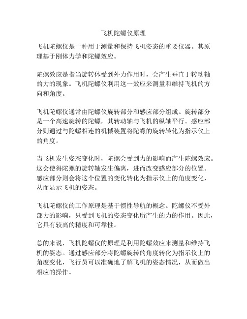
飞机陀螺仪原理
飞机陀螺仪是一种用于测量和保持飞机姿态的重要仪器。
其原理基于刚体力学和陀螺效应。
陀螺效应是指当旋转体受到外力作用时,会产生垂直于转动轴的力的现象。
飞机陀螺仪利用这一效应来测量和维持飞机的方向和角度。
飞机陀螺仪通常由陀螺仪旋转部分和感应部分组成。
旋转部分是一个高速旋转的陀螺,其转动轴与飞机的纵轴平行。
感应部分则通过与陀螺相连的机械装置将陀螺的旋转转化为指示仪上的角度。
当飞机发生姿态变化时,陀螺会受到力的影响而产生陀螺效应。
这会使得陀螺的旋转轴发生偏离,进而改变感应部分的位置。
感应部分则会将这个位置的变化转化为指示仪上的角度变化,从而显示飞机的姿态。
飞机陀螺仪的工作原理是基于惯性导航的概念。
陀螺仪不受外部力的影响,只受到飞机的姿态变化所产生的力的作用。
因此,它具有较高的精度和可靠性。
总的来说,飞机陀螺仪的原理是利用陀螺效应来测量和维持飞机的姿态。
通过感应部分将陀螺旋转的角度转化为指示仪上的角度变化,飞行员可以准确地了解飞机的姿态情况,从而做出相应的操作。
陀螺仪测量角速度原理

陀螺仪测量角速度原理
陀螺仪测量角速度原理
1. 陀螺仪基本原理
陀螺仪是一种能够测量角速度(Angular velocity)的传感器,它是模拟质量配重陀螺的原理,以克服重力和摩擦力而持续旋转的设备,又叫作陀螺稳定剂(Gyro stabilizer)。
假设把一个质量配重陀螺放在水平的平台上,它会维持一定方向。
但是当它偏离水平平台时,就会以自身旋转的方向,使它的质量配重沿着陀螺轴旋转,该质量配重的旋转角速度就等于质量配重陀螺的角度变化速率。
2. 工作原理
现代的陀螺仪使用接近传感器的原理,例如电位差放大器,来测量角度变化速率的变化。
在一个陀螺仪的质量配重陀螺中,有一个电极(electrode),当陀螺轴旋转的时候,该电极沿着质量配重陀螺中心轴的方向旋转,这个旋转的电极会产生一个电位差(potential difference),这就是陀螺仪的输出信号。
3. 优点与缺点
优点:
1)可以测量微小的角度变化速率;
2)稳定性高;
3)可以测量更大的范围;
4)响应快速;
5)易于使用和安装;
6)产生少量噪声。
缺点:
1)价格较为昂贵;
2)有时会受到外部的干扰;
3)会受到温度变化的影响;
4)容易受到摩擦、磨损的影响; 5)可能会出现漂移。
陀螺仪原理[1]
![陀螺仪原理[1]](https://img.taocdn.com/s3/m/dc8a9b29915f804d2b16c14f.png)
1)自由陀螺仪主轴不能指北的原因地球自转角速度的垂直分量w2使自由陀螺仪主轴相对子午面的视运动。
2)变自由陀螺仪为陀螺罗经的方法:控制力矩(controlling moment)(用My表示):为了克服由于地球自转角速度的垂直分量w2使自由陀螺仪主轴相对子午面的视运动,向陀螺仪施加的外力矩;控制力矩必须作用于陀螺仪的水平轴。
3)陀螺罗经获得控制力矩的方式按力矩的产生原理不同:直接产生法和间接产生法;按力矩的性质不同:重力控制力矩和电磁控制力矩;按力矩的产生方式不同:三大系列罗经的三种主要方式。
(1)安许茨系列罗经获得控制力矩的方式:将陀螺球重心下移的直接控制法获得控制力矩。
控制设备(controlling device):陀螺罗经产生控制力矩的设备(器件)。
陀螺球(gyrosphere):安许茨系列罗经是将双转子陀螺仪固定和密封在金属球内。
陀螺球具有主轴(ox轴)、水平轴(oy轴)和垂直轴(oz轴)。
陀螺球的重心G不在其中心O,而是沿垂直轴下移几毫米。
t = t1时,陀螺球位于A1处,此时主轴水平指东,q = 0,重力mg作用线通过陀螺仪中心O,重力mg不产生力矩(虽有力但力臂为零)。
t = t2时,随着地球自转,当,陀螺球位于A2处,此时主轴上升了一个q角(q ≠ 0),重力mg作用线不通过陀螺球中心O(有力臂a),重力mg的分力mgsinq 产生沿水平轴oy向的重力控制力矩My:My = mgsinq •a≈ mg a •q= M•qM = mga 最大控制力矩.控制力矩的大小与罗经结构参数和主轴高度角q 有关.控制力矩My使主轴产生进动速度u2,它使主轴正端自动找北(向子午面进动)。
根据赖柴尔定理:动量矩H矢端的线速度矢量u与外力矩矢量M大小相等方向相同:u = M陀螺罗经控制力矩My使罗经主轴产生的进动速度:u2= My = M•q安许茨系列罗经称为下重式陀螺罗经,控制力矩为重力力矩,属于机械摆式罗经。
飞机姿态仪工作原理
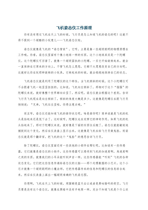
飞机姿态仪工作原理你有没有想过飞机在天上飞的时候,飞行员是怎么知道飞机的姿态的呢?这就不得不提到一个超酷的小玩意儿——飞机姿态仪啦。
姿态仪就像是飞机的“姿态管家”。
它呀,主要是靠一些超级聪明的物理原理在工作哦。
你看,姿态仪里面有个像小地球一样的东西,这个小地球其实是一个陀螺仪。
这个陀螺仪可厉害了,就像一个超级固执的小陀螺。
一旦它开始旋转起来,就会一直保持在它原来的方向上,不管飞机怎么晃悠,它都不太愿意改变自己的方向呢。
这就好比你在玩那种旋转的小玩具,它转起来的时候,就会稳稳地保持自己的状态。
飞机姿态仪就是利用了陀螺仪的这个特性。
当飞机倾斜的时候,这个小陀螺仪可不会跟着飞机一起歪歪扭扭的。
比如说,飞机向左倾斜了,那相对于这个“倔强”的陀螺仪来说,就好像整个世界都向右歪了。
然后呢,姿态仪就会根据这个差别,告诉飞行员飞机现在是向左倾斜了,倾斜的角度大概是多少。
这就像是陀螺仪在跟飞行员悄悄说:“兄弟,飞机往左歪啦,你得注意点哦。
”而且呀,姿态仪还能知道飞机的俯仰状态呢。
啥是俯仰呢?简单说就是飞机的机头是抬起来还是低下去了。
这时候呀,陀螺仪也在发挥它的神奇作用。
如果飞机的机头抬起来了,那对于陀螺仪来说,就好像是下面的东西往后跑了。
姿态仪就能敏锐地捕捉到这个变化,然后在仪表盘上显示出来。
这就像是飞机在给飞行员做鬼脸,而姿态仪就是那个翻译官,把飞机的这个“鬼脸”的意思告诉飞行员。
除了陀螺仪,姿态仪里面还有一些其他的小部件在帮忙呢。
比如说有一些传感器,它们就像是姿态仪的小助手。
这些传感器可以感受到飞机的加速度啊,角速度啊之类的东西。
就像我们的小耳朵能听到声音一样,这些传感器能“听到”飞机的各种状态变化。
它们把这些信息传递给姿态仪的大脑——那个处理数据的小芯片。
这个小芯片就像一个超级聪明的小魔法师,它把传感器传来的信息和陀螺仪的信息综合起来,然后在仪表盘上画出一幅超级准确的飞机姿态图。
你想啊,飞机在天上飞的时候,周围都是蓝天白云或者是黑咕隆咚的夜空。
北大航空航天概论陀螺仪

二、信号传感器
陀螺仪传感器是一个简单易用的基于自由空间移动和手势的定位和控制系统。 用来感测和维持方向的装置,它是航空、航海及太空导航系统中判断方位的 主要依据,并且在汽车安全,航模,望远镜等领域广泛应用。主要检测空间 某些相位的倾角变化、位置变化,主要用于空间物理领域,特别在航空、航 海方面有较多的用途,如:飞机上的陀螺仪,当飞机在做360°翻转的时候, 陀螺仪将会保持原始的基准状态不变,从而让驾驶员找到本飞机在空间状态 的相位变化,也就是:当时飞机处在什么相位。
⑤速率陀螺仪 用以直接测定运载器角速率的二自由度陀螺装置。把均衡陀螺仪的 外环固定在运载器上并令内环轴垂 直于要测量角速率的轴。当运载器连同外环以角 速度绕测量轴旋进时,陀螺力矩将迫使内环连同转子一起相对运载器旋进。陀螺仪 中有弹簧限制这个相对旋进,而内环的旋进角正比于弹簧的变形量。由平衡时的内 环旋进角即可求得陀螺力矩和运载器的角速率。积分陀螺仪与速率陀螺仪的不同处 只在于用线性阻尼器代替弹簧约束。当运载器作任意变速转动时,积分陀螺仪的输 出量是绕测量轴的转角(即角速度的积分)。以上两种陀螺仪在远距离测量系统或 自动控制、惯性导航平台中使用较多。
陀螺仪的原理:
根据牛顿第一运动定律,它会继续向左运动,但在陀螺仪的自转作用下又开始旋转, 如下图所示:
这种效应就是进动的成因。陀螺仪的不同部位在 同一点受力,但随后又转动到新的位置!当陀螺 仪顶端的部位向一侧转动90度时,会由于惯性而 继续保持向左运动的状态。底端的部位也是如 此——向一侧转动90度时,会由于惯性而继续保 持向右运动的状态。这些力沿进动方向转动车轮。 当标示的点继续转动的角度超过90度时,原来的 运动就停止了,于是陀螺仪的轴悬在空中并开始 进动。
④陀螺稳定器 20世纪初使用的施利克被动式稳定器实质上是一个装在船上的大型二自由度重力陀 螺仪,其转子轴铅直放置,框架轴平行于船的横轴。当船体侧摇时,陀螺力矩迫使 框架携带转子一起相对于船体旋进。这种摇摆式旋进引起另一个陀螺力矩,对船体 产生稳定作用。斯佩里主动式稳定器是在上述装置的基础上增加一个小型操纵陀螺 仪,其转子沿船横轴放置。一旦船体侧倾,小陀螺沿其铅直轴旋进,从而使主陀螺 仪框架轴上的控制马达及时开动,在该轴上施加与原陀螺力矩方向相同的主动力矩, 借以加强框架的旋进和由此旋进产生的对船体的稳定作用。
Fly RC IGyro 飞行器旋转陀螺仪说明书
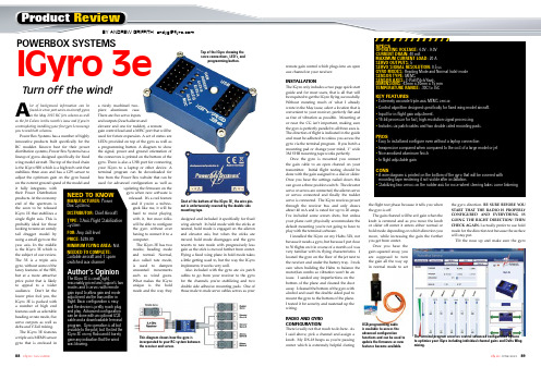
remote gain control which plugs into an openaux channel on your receiver.INSTALLATIONThe IGyro only includes a two page quick startguide and for most users, that is all that willbe required to get the IGyro flying successfully.Without restating much of what I alreadywrote in the May issue, select a location that isconvenient to your receiver, perfectly flat andas free of vibration as possible. Mounting ator near the CG isn’t important, making surethe gyro is perfectly parallel to all three axes is.The direction of flight is indicated in the guideand must be adhered to unless you access thegyro via the terminal program. If you botch amounting pad or change your mind, 1” wide3M VHB mounting tape works perfectly.Once the gyro is mounted you connectthe gain cable to an open channel on yourtransmitter. Initial flight testing should bedone with the gain assigned to a dial or slider.Once you have the settings nailed down thiscan go on a three position switch. The elevatorservo or servos are connected, the aileron servoor servos connected and finally the rudderservo is connected. The IGyro receives powerthrough the receiver bus and only drawsabout 40 mA and is rated for up to 20 amps.I’ve included some screen shots, but unlessyour plane can’t physically accommodate thedefault mounting you’re not going to have toplay with the terminal software.I installed the IGyro on my Habu 32X, notbecause it needs a gyro, but because I put closeto 50 flights on it in course of a month so I wasvery familiar with its flying characteristics. Ilocated the gyro on the floor of the jet next tothe receiver and under the battery tray. I tookcare when building the Habu to balance themotor/fan combo so vibration won’t be anissue. I sanded any imperfections on thebottom of the plane and cleaned the dustaway. I cleaned the bottom of the gyro withalcohol and used the double sided pad tomount the gyro to the bottom of the plane.I tested it for security and neatened up thewiring.RADIO AND GYROCONFIGURATIONThere’s really not that much to do here. AsI said above, pick a channel and assign aknob. My DX-18 beeps as you’re passingcenter which is extremely helpful duringthe flight test phase because it tells you whenthe gyro is off.The gain channel will be at 0 gain when theknob is centered and as you move the knobor slider off center it enters either normal orhold mode depending on which direction youmove, while increasing the gain the furtheryou get from center.Once you have thegain squared away, youare supposed to turnthe gain all the way upin normal mode to setthe gyro direction. BE SURE BEFORE YOUSTART THAT THE RADIO IS PROPERLYCONFIGURED AND EVERYTHING ISGOING THE RIGHT DIRECTION! THENCHECK AGAIN. I actually prefer to use holdmode for the direction test because the surfacewill stay put.Tilt the nose up and make sure the gyro ReviewBY ANDREW GRIFFITH ***************A lot of background information can befound in a two part series on aircraft gyrosin the May 2015 RC Jets column as wellas the Jet Colum in this month’s issue and if you’recontemplating installing your first gyro I encourageyou to read both columns.Power Box Systems has a number of highlyinnovative products built specifically for theRC modeler. Known best for their powerdistribution systems, Power Box Systems has alineup of gyros designed specifically for fixedwing model aircraft. The top of the food chainis the IGyro SRS which is a high tech unit thatstabilizes three axes and has a GPS sensor toadjust the optimum gain on the gyro basedon the current ground speed of the model andit fully integrates withtheir Power Distributionproducts. At the economyend of the spectrum isthe soon to be releasedIGyro 1E that stabilizes asingle flight axis. This isprobably ideal for thoselooking to tame an unrulytail dragger model byusing a small gyro on theyaw axis. In the middleis the IGyro 3E which isthe subject of our review.The 3E is a triple axisgyro, without some of thefancy features of the SRS,but at a more attractiveprice point that is likelyto appeal to a wideraudience. Don’t let thelower price fool you, theIGyro 3E is packed witha number of high endfeatures such as selectableheading or rate mode, fiveservo outputs as well asdelta and V-Tail mixing.The IGyro 3E featuresa triple axis MEMS sensorgyro that is enclosed ina nicely machined two-piece aluminum case.There are five servo inputsand outputs (2 each aileron andelevator and one for rudder), a remotegain control lead and a MISC port that will beused for future expansion. A set of status areLED’s provided on top of the gyro as well asa programming button. A diagram to showthe signal, power and ground orientation ofthe connectors is printed on the bottom of thegyro. There is also a USB port for connectingyour IGyro to a laptop or other device. Aterminal program can be downloaded forfree from the Power Box website that can beused for advanced configuration as well asupdating the firmware on thegyro when new software isreleased. It’s a cool featureand if you’re a techno-geek like me, it will behard to resist playingwith it, but most folkswill be able to configurethe gyro without everhaving to connect it to acomputer.The IGyro 3E has twomodes; heading modeand normal. Normal,also called rate mode,is used to dampenunwanted movementssuch as wind gusts.What makes the IGyrounique is the holdmode and the way theydesigned and included it specifically for fixedwing aircraft. In hold mode with the sticks atneutral, hold mode is engaged on the aileronand elevator axis, but when the sticks aremoved, hold mode disengages and the gyroreverts to rate mode with progressively lessgain as the stick is moved further from center.Flying a fixed wing plane in hold mode takesa little getting used to, but the way the IGyroimplements it works very well.Also included with the gyro are six patchcables to go from your receiver to the gyrofor the channels you’re stabilizing and twodouble side adhesive mounting pads. One ofthose male to male servo cables serves as yourSPECSOPERATING VOLTAGE: 4.0V – 9.0VCURRENT DRAIN: 40 mAMAXIMUM CURRENT LOAD: 20 ASERVO OUTPUTS: 5SERVO SIGNAL RESOLUTION: 0.5 usGYRO MODES: Heading Mode and Normal (rate) modeSENSOR TYPE: MEMSSENSOR AXES: 3 (Roll/Pitch/Yaw)DIMENSIONS: 43mm x 30mm x 15 mmTEMPERATURE RANGE: -30C to 75CKEY FEATURES• Extremely accurate triple-axis MEMS sensor.• Control algorithm designed specifically for fixed wing model aircraft.• Input for in-flight gain adjustment.• 16-bit processor for fast, high-resolution signal processing.• Includes six patch cables and two double sided mounting pads.PROS• Easy to install and configure even without a laptop connection•• Nice anodized aluminum finish• In flight adjustable gainCONS•mounting tape rendering it not visible after installation.•Turn off the wind!NEED TO KNOWMANUFACTURER:DISTRIBUTOR:TYPE:FOR:PRICE:MINIMUM FL YING AREA:NEEDED TO COMPLETE:POWERBOX SYSTEMSIGyro 3e Top of the IGyro showing the servo connections, LED’s, and programming button.Shot of the bottom of the IGyro 3E, the wire pin-out is unfortunately covered by the double sidemounting tape.This diagram shows how the gyro isincorporated to your RC system betweenthe receiver and servos.USB programming cableis available to access theadvanced configurationfunctions and can be used toupdate the firmware as newfeatures become available.The terminal program accesses several advanced configuration optionsto optimize your IGyro including individual channel gains and Delta Wingmixing.gives down elevator. Roll right and make sure the gyro inputs left aileron, nose left and you should see right rudder. The rudder will return to center because it doesn’t use hold mode. If anything is backwards simply press the setup button until all the lights go out. At that point Aileron A will be lit, if that servo is correcting backwards tap the button otherwise hold it and it will move to the next servo. Any servos that need reversed should be and that setting is saved immediately.Perform a full control and gyro direction test again. Then do it with a friend watching to double check. I may sound redundant, but if the gyro is correcting backwards for aileron, for example, and the plane starts rolling right, the gyro will make it roll harder; not correct it. The result will either be having the presence of mind to zero the gain, landing and changing your pants or retrieving the model with a Dust Buster. I’ve seen backwards tail rotor gyros a lot and have done it myself during late night building sessions so I speak from learning the hard way here.FLIGHT TESTINGI couldn’t have asked for a betterday to test the IGyro. The wind wasblowing at 8 to 10mph right downour primary runway, but it was alsoa 90 degree cross wind to our secondrunway that is generally used bythe helicopter and foamie crowd.With the gain set at 0, I advancedthe throttle and took off and nothinghappened. So far so good! With afew mistakes between my Habu andthe ground and about 60-percentpower I advanced the gain until I could see some oscillations which occurred first on the aileron axis. I brought the jet down low at full throttle now that I had my confidence up and tweaked the gain as high as I could get in normal mode at full speed without getting any shimmy. A few laps at both high and low speed gave me the impression that the Habu was flying exactly as before, the difference being that it seemed utterly unperturbed by the wind gusts. I set up for landing and the approach was rock solid right to the ground. I brought the end point down on the normal side so that I could move the lever all the way to the end and swapped a fresh pack in to play with hold mode. I took off again with the gyro in normal mode and the slider all the way forward. Since it doesn’t control the nose wheel I didn’t notice any effect on the ground, but it climbedsmoothly away. I performedthe same procedure as above, slowly raisingthe gain until it oscillated, flying low and fast.Hold mode is really something. Roll invertedin normal and it will slowly arch toward theground, but if you roll inverted in Hold andestablish your line, the plane remains leveland rock solid. Point rolls stop when youlet go and only minor rudder correction isneeded for knife edge where the pitch androll stay put. Flying in Hold mode takes alittle getting used to, but before my timer wastelling me to land I was in a groove.This time I setup my approach on thehelicopter runway with a stiff crosswind.Leaving the gyro in Hold mode, the Habulanded just like I was landing into the wind,albeit with a slightly higher ground speed. Iflew in Hold mode almost exclusively afterthat flight though I did spend a little timedecreasing the end pointand getting the mostgain I could without oscillation. At the end ofthe day I setup the gainon a switch and addeda mix to my gear switch that kicked up the gainby 5 percent when the wheels are down.CONCLUSIONIn calm winds on a good flying plane you mightthink that you wasted your money on a gyro. If the plane is a handful though, you might think you are flying a completely different and well behaved plane.When the wind picks up, however, the plane keeps right on flying the same way … like it’s on rails. Cross wind landing? No problem. A gyro won’t add power when you’re going to stall and it won’t overcome something the airplane isn’t aerodynamically capable of doing. What it will do is make minor corrections at a rate that no human pilot is capable of. How many times do you go to an event and weather is less than ideal? Depending on the distance and the event, that might be a significant investment in time and money. You’ll still be flying with your IGyro at a much higher comfort and enjoyment level. Flying a twin and an engine goes out and you need enough time to get your wits about you? The IGyro will be correcting the rudder before you know you have a problem. Note that I used the IGyro in a ducted fan jet because it tied in nicely with my Jets column, but the IGyro is appropriate in any fixed wing aircraft and I plan on flying it on a few different airframes. To the naysayers that talk about cheating or about the gyro flying the plane, enjoy listening to your 8 track on the way to the field. Flying an IGyro will increase your enjoyment, making you fly more, whichin the end will make you a better pilot. b CONTACTS CHIEF AIRCRAFT ,(800) 447-3408E-FLITE RC , (217) 352-1913SPEKTRUM (217) 352-1913POWER BOX SYTESMS For more information, please see our source guide on page 97.POWERBOX SYSTEMS IGYRO 3EPopup hints explain the various settings and functions.IGyro 3E mounted next to the receiver in my Habu 32x. Before I cleanedup the wiring!The Habu 32X made a great test bed and flew extremely well when the windkicked up. On a calm day it wasn’t even noticiable.。
陀螺仪
学习直升机基础知识陀螺仪陀螺仪的功用直升机飞行的基本原理是利用主旋翼(main rotor,main blade,propeller)可变角度产生反向推力而上升,但对机身会产生扭力(torque force)作用,于是需要加设一个尾旋翼(tail)来抵消扭力,平衡机身,但怎样使尾旋翼利用合适的角度,来平衡机身呢?这就用到陀螺仪(gyro)了,它可以根据机身的摆动多少,自动作出补偿讯号给伺服器(servo),去改变尾旋翼角度,产生推力平衡机身。
以前,模型直升机是没有陀螺仪的,油门、主旋翼角度和尾旋翼角度很难配合,起动后便尽快往上空飞(因为飞行时较易控制),如要悬停就要控制杆快速灵敏的动作,所以很容易撞毁,现在已有多中直升机模型使用的陀螺仪,分别有机械式、电子式、电子自动锁定式。
有下列几类:1. 机械式陀螺仪,较便宜的一种。
分一段及两段灵敏度调校的型号,耐震较弱。
2. 电子晶体震动陀螺仪(Piezzo),效能较高,需配合特别舵机。
由於输出讯号较多,故耗电率高,价钱固然高一些啦。
3. 电子定向陀螺仪(Head Lock Gyro),它的操作和平常的陀螺仪不同,方向性有极高表现。
操纵尾舵时需要小心,它需要作反向操纵才能回复直线飞行,即是一经操纵转舵,便继续转弯直至你作反向修正。
地面效应当直升机接近地面时会产生地面效应,直升机离地滞空时,旋翼把空气向下抽,因此旋翼和地面之间的空气密度变大,形成气垫效果,浮力会变佳,离地越近,效果越佳,但是因为空气被压缩,无处逸散而产生乱流,导致停悬的不稳定,所以R/C直升机在接近地面时会呈现不稳定现象而比较难控制,产生这种气垫效果的高度大约是旋翼面直径的一半左右。
反扭力高速转动的主旋翼,有一定的速度和质量,除了会产生陀螺效应外,更有反扭力的产生,尾旋翼主要的功用就是平衡反扭力使机身不自转,但现在的R/C 直升机均采用可变攻角形态,油门的加减,攻角的变化...等因素使得反扭力千变万化,尾旋翼产生的平衡力也要跟著快速变化,以保持机身的稳定,现在的R/C 直升机采用各种的措施来平衡瞬息万变的反扭力。
基于四旋翼飞行器的陀螺仪、加速度计、磁力计传感器说明

一什么是磁力计、加速度计和陀螺仪以及他们之间的区别1、什么是陀螺仪、加速度计和磁力计?(1)陀螺仪(Gyroscope、GYRO-Sensor)也叫地感器,三轴陀螺仪的工作原理是通过测量三维坐标系内陀螺转子的垂直轴与设备之间的夹角,并计算角速度,通过夹角和角速度来判别物体在三维空间的运动状态。
三轴陀螺仪可以同时测定上、下、左、右、前、后等6个方向(合成方向同样可分解为三轴坐标),最终可判断出设备的移动轨迹和加速度。
也就是说陀螺仪通过测量自身的旋转状态,判断出设备当前运动状态,是向前、向后、向上、向下、向左还是向右呢,是加速(角速度)还是减速(角速度)呢,都可以实现,但是要判断出设备的方位(东西南北),陀螺仪就没有办法。
(2)加速度计(Accelerometer、G-Sensor)也叫重力感应器,实际上是可以感知任意方向上的加速度(重力加速度则只是地表垂直方向加速度),加速度计测量组件在某个轴向的受力情况来得到结果,表现形式为轴向的加速度大小和方向(XYZ),这一点又有点类似于陀螺仪,但陀螺仪的更多关注自身旋转情况(原位运动),加速计则主要是测量设备的受力情况,也就是三轴运动情况,尽管加速计也可能在某个小范围换算出角速度的可能,但设计原理决定似乎更适合于空间运动判断。
(3)磁力计(Magnetic、M-Sensor)也叫地磁、磁感器,可用于测试磁场强度和方向,定位设备的方位,磁力计的原理跟指南针原理类似,可以测量出当前设备与东南西北四个方向上的夹角。
2、陀螺仪、加速度计和磁力计三个传感器强项(1)陀螺仪的强项在于测量设备自身的旋转运动。
(2)加速度计的强项在于检测设备的受力情况。
(3)磁力计的强项在于检测设备的方位。
3、具体作用:陀螺仪知道“我们转了个身”,加速计知道“我们又向前走了几米”,而磁力计则知道“我们是向西方向”的。
二问答(1)在飞行器中使用的磁力计、加速度计、陀螺仪等传感器在安装之前为什么要先校准?答案:由于一般传感器的精度会随着使用的时间和温度变化而变化,时间久了,传感器会有一定的零点漂移,这时候就要对它进行标定,将传感器在使用中或存储后进行的性能复测称为校准,其本质与标定是相同的。