Step-Servo_Quick_Tuner_用户手册_-_中文.pdf
埃斯顿伺服器用户手册
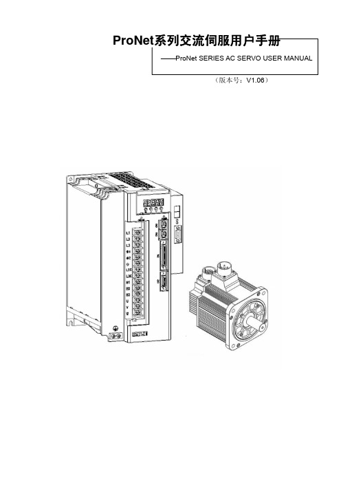
P roNet系列交流伺服用户手册P roNet SERIES AC SERVO USER MANUAL(版本号:V1.06)手册概要⏹本手册以ProNet型伺服驱动器的用户为对象,就下列内容作以说明:·伺服电机及伺服单元的到货确认及规格型号·伺服电机及伺服单元的安装方法·伺服电机及伺服单元的配线方法·伺服驱动器的运行方法·面板操作器的使用方法·通讯协议·伺服电机及伺服单元的技术规格和特性⏹本手册的适用阅读对象如下:·ProNet伺服驱动器的程序设计及详细设计工作者·ProNet伺服驱动器的安装及配线工作者·ProNet伺服驱动器的试运行及伺服调整工作者·ProNet伺服驱动器的维护及检修工作者⏹本手册中基本术语的含义:本手册中,在没有特殊说明的情况下,下列术语所表达的意思如下∶伺服电机:EMG,EMJ,EML,EMB 型伺服电机伺服单元:ProNet型伺服单元伺服驱动器:一组伺服电机与伺服单元伺服系统:由伺服驱动器与上级装置以及外围机器配套组装成的一组伺服控制系统[使用前的注意事项]■严禁将伺服电机直接与市网电源连接。
严禁将伺服电机直接与市网电源连接,极易损坏伺服电机。
伺服电机没有伺服单元的支持,不能旋转。
■接通电源后禁止插、拔驱动器上的接插件。
带电插、拔极易损坏驱动器的内部电路和电机编码器,请在断电后再插、拔接插件。
■断电5分钟后才能进行伺服系统的检查作业。
即使切断电源,伺服单元内部的电容中仍然存储有相当的电量,为了防止触电事故的发生,建议在确认CHARGE指示灯灭之后,再过5分钟才能开始进行伺服系统的检查操作。
■伺服单元与电柜中其它设备的安装间隔需保持在10mm以上。
伺服单元易发热,应尽可能选择有利于散热的安装布局,与电柜中其它设备的横向间隔最好在10mm以上,纵向间隔最好在50mm以上,安装环境最好不受结露、振动、冲击的影响。
埃斯顿PRONET用户手册

耐热等级
F
环境温度
0 to +40℃ (不结冻)
环境湿度
20% to 80% RH (不结露)
保护方式
全封闭,自冷,IP65 (除输出轴承和连接器)
抗振性能
49m/s2
注:括号内的数值表示的是带制动器电机的值。
● 转矩-转速特性 (A:连续工作区域,B:反复工作区域)
10A□A□□ 1000 3.18 9.55 5.3 15.9
ESTUN 伺服电机 EML 型
【1+2】 【3】 【4】 【5】 【6】 【7】
【1+2】额定输出功率
记号
规格
10 1.0kW
27.0 14.5(15.1)
36.0 2000 3000 19.0(19.6)
编码器
标准 选项
17 位增量式:131072P/R 17 位绝对值:131072P/R; 旋转变压器
耐热等级
F
环境温度
0 to +40℃ (不结冻)
环境湿度
20% to 80% RH (不结露)
保护方式
全封闭,自冷,IP65 (除输出轴承和连接器)
AC 伺服驱动器
ProNet 用户手册
ESTUN
产品体系
小功率
系列
EMJ
3000min-1
EMG
2000min-1
EML
1000min-1
EMB
1500min-1
伺服电机
功率
200W 400W 750W 1000W 1.0kW 1.5kW 2.0kW 3.0kW 5.0kW 1.0kW 2.0kW 3.0kW 4.0kW 7.5kW 11kW 15kW
ESTUN 伺服电机 EMG 型
STEP机器人快速操作手册-B
9. 选中“AXISPOS”,点击“确认”。
12. “保存”弹出的编程语句。
13. 手动模式下运行程序: 长按三位开关上使能,一直按住示教 器控制面板右侧“ ”键,此时机 器人就会由当前点运动到终点位置, 程序状态栏右上方会变成“ ”;(若 想中途暂停机器人运动,只需松开 “ ”键,状态变为“ ”;若要 继续运行,就再次按下“ ”键;) 运行结束后松开三位开关断使能,此 时状态变为“ ”。
机器人快速操作手册
手册概述
关于本手册
本手册为机器人操作的快速入门手册,旨在短时间内提升客户对机器人的熟 知度。
操作前提
操作机器人前,请务必仔细阅读《STEP 机器人操作安全手册》,用户需在了 解安全知识的基础上才可使用机器人。
目标群体
操作人员 产品技术人员 技术服务人员 机器人程序员
手册说明
本手册内容会有补充和修改,请经常留意我公司网站,更新操作手册。 我公司官方网址:。
5. 依次点击“示教”“OK”,当前点示教完成。 6.“保存”弹出的程序,再点击“新建”。
8
SPD-13-00-B
机器人快速操作手册
7. 点击“运动语句”,选中“PTP”。
8. 选中“pos:Postion”,点击“新建”。
10. 示教要到达的位置点:按下三位开关(一 直按),点动示教器控制面板右侧“+”“-” 键,把机器人移动到自己想要的位置后, 松开三位开关。
LED-Motion 变亮。
4. 上使能保持三位开关 按住,另一只手依次点动示 教器控制面板右侧“+”“-” 按键,确认六个轴可以正常 运行。每一行“+”“-”键代 表各个轴运动的相反方向。 松开按键,机器人停止运动, 松开开关,机器人使能断掉。 (注意:机器人运动过程中 不能断使能,否则会报错)
伺服软件使用说明_最简洁版

ECO2WIN使用说明-简洁版深圳市步科电气有限公司目录第一部分: 特别需要注意的事项 (3)第二部分: 建立一个简单的工程 (9)第三部分: 进行简单的控制 (16)1功能介绍 (16)2 驱动器关键参数的设置 (17)电机参数设置 (17)电流环参数 (19)速度环PID调节 (20)位置环PID调节 (21)3 保存参数: (22)4 绝对位置、相对位置控制 (25)5 速度模式 (27)6 原点模式 (29)7 脉冲方向控制模式(跟随模式) (30)第四部分: 故障诊断 (34)第一部分: 特别需要注意的事项1、EC2WIN的所有文件,包装安装文件、电机参数文件、工程文件等都需要您放在英文目录下,同时必须详细阅读该手册里所有粗体或者带颜色的字体,运行电机前请确保所有连接线均正确连接到驱动器上;2、PC与ED伺服之间的连线为2、3、5脚直连线;3、如果您使用的是ED400、ED430、ED600、ED630系列的伺服驱动器,请先更新软件再进入下一步。
更新软件方法如下:把附件里的“DEV”文件夹里的两个文件解压出来,然后复制到EC2WIN的安装目录D:\Program Files\JAT\ECO2WIN\Dev里的两个文件“ENU和DEU”两个文件夹,替换以前的这两个文件即可。
4、如果您使用的3相电机,那么在新建或者连接已经建好的工程之前先用ECO2LOAD软件更新电机参数,三相电机的参数文件请参考附件,这些参数包括位置环、速度环、电流环、电机参数设置等参数,这样可以节省您设置这些参数的时间,同时也避免不小心设置成一个错误的值。
更新方法如下:1、打开“开始”菜单里的ECO2LOAD软件:2、然后进入软件界面:Write data into device:写参数到伺服驱动器;Read date out-of device:从伺服里读参数到文件Administration:管理伺服驱动器,用于重启和存储参数Load parameter list:选择读、写参数的内容,用来选择所要读取和做写入的是驱动器的哪些参数,正常情况下不用动这个按钮。
Quick 8802 系列数控伺服控制系统使用说明书
Quick 8802 系列数控伺服控制系统使用说明书 Digital Servo Control System Operation Manual安全操作指南 General safety instructions在使用前,一定要仔细阅读本操作指南与所搭配的缝制机械说明书,配合正确使用,并须由接受过专业培训的人员来安装或操作。
在使用或安装本机器时,请注意下列事项。
Please read this manual carefully, also with related manual for the machine head before use. For perfect operation safety , i nstalling and operating this product by trained personnel is required. When install and operate this product, precaution must be taken as following.1 .请尽量远离电弧焊接设备或电波发射器等,以免产生的电磁波干扰本控制器而发生误动作。
2 .请不要在室温 45 °C 以上或者 0 °C 以下的场所使用。
3 . 请不要在湿度 30 % 以下或者 95 % 以上或者有露水和酸雾的场所使用。
4 .安装控制箱及其他部件时,请先关闭电源并拔掉电源插头。
5 .为防止干扰或漏电事故,请做好接地工程,电源线的接地线必须以牢固方式与大地有效连接。
6 .所有维修用的零部件,须由本公司提供或认可,方可使用。
7 .修理及保养作业,要请经过培训的技术员执行。
在进行任何保养维修动作前,必须关闭电源并拔掉电源插头。
控制箱里有高压危险,必须关闭电源五分钟后方可打开控制箱。
8 .本手册中标有 符号之处为安全注意点,必须注意并严格遵守,以免造成不必要的损害。
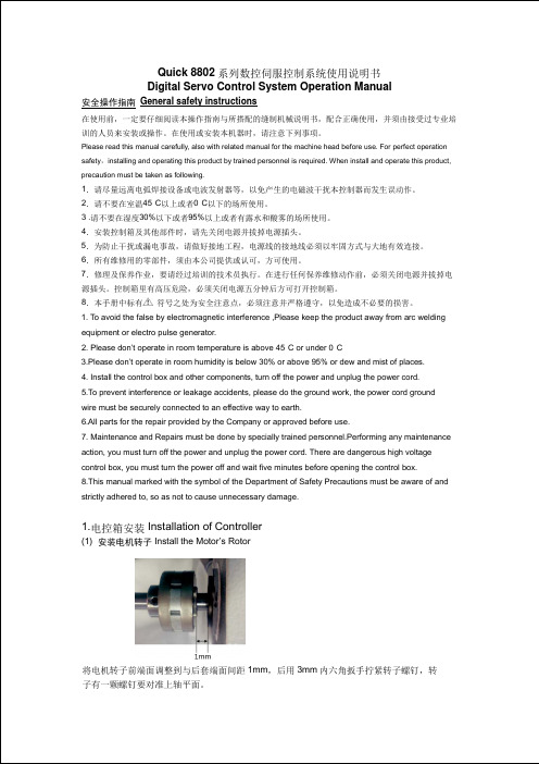
. To avoid the false by electromagnetic interference ,Please keep the product away from arc welding 1 equipment or electro pulse generator.2 . Please don’t operate in room temperature is above 45°C or under 0°C ·3 .Please don’t operate in room humidity is below 30% or above 95% or dew and mist of places.4 . Install the control box and other components, turn off the power and unplug the power cord.5 .To prevent interference or leakage accidents, please do the ground work, the power cord ground wire must be securely connected to an effective way to earth.6 .All parts for the repair provided by the Company or approved before use.7 . Maintenance and Repairs must be done by specially trained personnel.Performing any maintenance action, you must turn off the power and unplug the power cord. There are dangerous high voltage control box, you must turn the power off and wait five minutes before opening the control box. 8 .This manual marked with the symbol of the Department of Safety Precautions must be aware of and strictly adhered to, so as not to cause unnecessary damage.1. 电控箱安装 Installation of Controller(1) 安装电机转子 Install the Motor’s Rotor将电机转子前端面调整到与后套端面间距1mm ,后用3mm 内六角扳手拧紧转子螺钉,转 子有一颗螺钉要对准上轴平面。
ESTUN SERVO SYSTEM 伺服系统说明书
SERVO SYSTEMGeneral Automation Product ProductFamilyTechnicalFeatureDesignValueService ● Having a number of offi ces and service outlets home and abroad to provide fast response to customers' needs● 24-hour technical service hotline● Genius service● F1000 HMI Series (Size 7” 10” )● EP1000 PLC Series (Up to 256 Local DI / DO, PLC with network)● ESMotion MC Series (Programmable, Modular structure motion controller)● Open CNC composed by F1000 & ESMotion & EP1000 Freely● 20 years of professional design of automatic control systems, commissioning experience● Not only provide a single product, but also specializes in providing total solutions● Not only design standerd products, but also customize products● Better understanding of customer needs, know how to increase the value of your project● Desined by embedded systems, open architecture, modular concept● Standard fi eld bus, Modbus TCP, CANopen, EtherCAT● Based on hardware and software platform, HMI, PLC, MC integration together perfectly● Modular hardware design and fi eld bus Connection● Software design tends to flexible, user-friendly, easy to secondary development and powerful encryptionProvide total solution for varies applications2D / 3D machineSpring machineScara robot Punching manipulatorCNC engravingand milling machineWood engraving andmachining centersQuilting machineSewing machinePacking machineRotary shear / fl y cuttingFeaturesProNet Series AC Servo SystemServo Drive(ProNet-E)●Wide range, various models: 0.05kW ~ 22kW ●Current forward feedback control, acceleration forward-feed: high responsiveness Multiple feedback options: 17bits serials encoder, 2500P/R encoder, resolver Various communication protocols: CANopen, EtherCAT, POWERLINK, PROFIBUS, Modbus machine, wood making machine, packing machine, textile machine, printing machine, robot arm,ADD: 16 Shuige Road, Jiangning Development Zone,Nanjing 211106, P .R.ChinaTEL: +86-25-52785960FAX: +86-25-52785576Hohai UniversityJiangning CampuspusESTUNDaoCheng Xin Da Dao S55 Ning Xuan Gao Suo Su Jiang Jun Da Dao Yun Qi Jie Fo Cheng Xi LuFo Cheng Dong LuSu Yuan Da Dao T o d o w n t o w n Nanjing SouthRailway StationTian Yuan Xi LuAirport Express Shui Ge LuShui Ge Lu Nanjing Lukou Int’l AirportJiang Jun Da Dao ShanghaiAirp ESTUN AUTOMATION TECHNOLOGY CO.,LTD E-mail:**************DriveVersion: GAP-201411。
ServoGun_TC_4.1 翻译本
1 介绍................................................................................................................................................. - 5 1.1 用户组....................................................................................................................................- 5 1.2 相关工业机器人文档............................................................................................................- 5 1.3 安全图标及其含义................................................................................................................ - 5 1.4 术语........................................................................................................................................ - 6 -
2 产品描述......................................................................................................................................... - 8 2.1 伺服焊接包——概览............................................................................................................- 8 2.2 连续运动速度......................................................................................................................- 10 2.3 连接电缆概述......................................................................................................................- 10 2.4 技术包的使用目的.............................................................................................................. - 11 -
诺普特智能控制系列Servo驱动器及Servomotor说明书
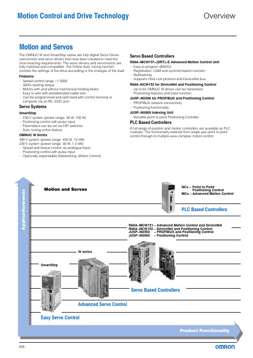
Motion and ServosThe OMNUC W and SmartStep series are fully digital Servo Drives (servomotor and servo driver) that have been created to meet the most exacting requirements. The servo drivers and servomotors are fully matched and compatible. The Online Auto−tuning function controls the settings of the drive according to the changes of the load. Features:−Speed control range >1:5000−300% starting torque−Motors with and without mechanical holding brake−Easy to wire with prefabricated cable sets−Can be programmed and optimised with control terminal or computer via an RS−232C port.Servo SystemsSmartStep−230 V system (power range: 30 W..750 W)−Positioning control with pulse input−Parameters can be set via DIP switches−Auto−tuning online featureOMNUC W Series400 V system (power range: 450 W..15 kW)230 V system (power range: 30 W..1.5 kW)−Speed and torque control via analogue Input−Positioning control with pulse input−Optionally expandable (Networking, Motion Control)Servo Based ControllersR88A–MCW151–(DRT)–E Advanced Motion Control Unit−Easy to program (BASIC)−Registration, CAM and synchronisation function−Multitasking−Supports Host Link protocol and DeviceNet busR88A–NCW152 for DeviceNet and Positioning Control−Up to 63 OMNUC W drives can be networked−Positioning features and trace functionJUSP–NS500 for PROFIBUS and Positioning Control−PROFIBUS network connectivity−Positioning functionalityJUSP–NS600 Indexing Unit−Versatile point to point Positioning ContollerPLC Based ControllersA full range of position and motion controllers are available as PLC modules. The functionality extends from single axis point to point control through to multiple axes complex motion controlMotion Control and Drive Technology OverviewThe SmartStep series has been designed to address the requirements of the low cost point−to−point motion market. These include fast response, accuracy and reliability. The SmartStep is an ideal alternative to stepper motors.The controller features Positioning Control with pulse input.The power range of this series ranges from 30 W..750 W, equivalent to 0.318..2.39 Nm of torque at 3000 rpm. The supply voltage is 230 V (50/60 Hz; single−phase).Characteristics:−Very compact design of motor and drive−Max. motor speed 4500 rpm, speed control range >1:5000−Rapid commissioning with the Online Autotune function−Motors available with and without mechanical holding brake−Parameters can also be set via DIP switches−300% acceleration torque−Easy to wire with prefabricated cable sets−Low weight−Convenient to operate from a control terminal−Computer programmable via RS−232CportSystem layout for simple positioning application.MotionandServosSystems without holding brake (3000 rpm motors)Systems with holding brake (3000 rpm motors)Encoder cable/motor cable without holding brake: R7A–CEAxxx–S Encoder cable/motor cable with holding brake: R7A–CEAxxx–B xxx = Cable length (see Accessories, page 364).SpecificationsCylindrical design motors without/with holding brakeSpecification for cylindrical design motors with holding brakeM o t i o n a n d S e r v o sCube design motors (without/with holding brake)Specification for cube design motors with holding brakeSmartStepM o t i o n a n d S e r v o sCables and Terminal block connections between SmartStep Servo drive and the PLC Positioning Control Unit. Without communications support.* 2 Terminal blocks and 2 Cables to the PLC are required for the C_W−NC4xx Units (4 axes).Cables and terminal block connections between SmartStep Servo drive and the PLC Positioning Control Unit.With communications support.blocks and 2 Cables to Other accessoriesProgramming and DocumentationProgrammingTechnicalDocumentationServo driver, 230 VLine filter, footprint, 230 VServomotors, cylindrical design (without brake), 230 VServomotors, cylindrical design (with brake), 230 VServomotors, cube design (without brake), 230 VServomotors, cube design (with brake), 230 VM o t i o n a n d S e r v o sMotion Control andMotion and Servos − SmartStep Drive TechnologyThe OMNUC W series is an advanced servo system designed to meet the demands of machine design. Motors and drives are fully matched and compatible. The optimum controller setting is continuously computed during operation by an online self−optimising function, so the servo always operates with maximum dynamics irrespective of load.The OMNUC W Series offers speed/torque and positioning control in a single unit. The servo drivers are available with a three−phase 400 V supply in a power range from 200 W..15 kW or single−phase 230 V supply in a power range from 30 W..1.5 kW.Characteristics:− All−in−One" compact controller with speed/torque and positioning control−Expandable with optional slot for positioning, advanced Motion control and networking−Motor protection class:200V class, IP55400V class, IP67, optional IP55−Speeds up to 6000 rpm−High resolution serial encoder, up to 17 bits−Extremely short cycle times for speed and position controller, producing maximum dynamicresponseExample of a system layout for simple motion control application with one CS1.MotionandServos230V classCylindrical design motorsSystems without holding brake (3000 rpm motors)Systems with holding brake (3000 rpm motors)Cube design motorsSystems without holding brake (3000 rpm motors)Systems with holding brake (3000 rpm motors)400V classCylindrical design motorsSystems without holding brake (1500 rpm motors)Systems with holding brake (1500 rpm motors)Systems without holding brake (3000 rpm motors)*Encoder cable for 300 and 650 W motors, R88A–CRWAxxxC–DE MotionandServos400V classSystems with holding brake (3000 rpm motors)*Encoder cable for 300 and 650 W motors, R88A–CRWAxxxC–DE A separate brake cable is not required for 300 and 650 W motors. Systems without holding brake (6000 rpm motors)Systems with holding brake (6000 rpm motors)Cube design motorsSystems without holding brake (3000 rpm motors)Systems with holding brake (3000 rpm motors)**Encoder cable for cube design motors, R88A–CRWAxxxC–DEA separate brake cable is not required for cube design motors.230V classServo driverType codingServomotors 200 VM o t i o n a n d S e r v o s230V classServomotor, rated speed 3000 rpm (cylindrical design)Servomotor, rated speed 3000 rpm (cube design)Motors with absolute encoder and special models are available. Please, contact your local Omron Office.400V classServo driver400V classServo driverType codingServomotors 400 VServomotor, rated speed 1500 rpm (cylindrical design)M o t i o n a n d S e r v o s400V classServomotor, rated speed 1500 rpm (cylindrical design)Servomotor, rated speed 3000 rpm (cylindrical design)400V classServomotor, rated speed 6000 rpm (cylindrical design)Servomotor, rated speed 3000 rpm (cube design)Motors with absolute encoder and special models are available. Please, contact your local Omron Office.MotionandServosfor Positioning ControlOMNUC Wfor Speed/Torque ControlM o t i o n a n d S e r v o sCable and Terminal block connections between OMNUC W Servo drive and te PLC Positioning Control Unit.* 2 Terminal blocks and 2 cables to the PLC are required for the C_W−NC4xx Units (4 axes).Cable and Terminal block connections between OMNUC W Servo drive and the PLC Motion Controller Units*The CS1W−MC421 Unit (4 axes) requires 2 cables.Cable and Terminal block connections between OMNUC W Servo drive and the Advanced Motion Controller Unit C200HW–MC402–EMotionandServosOther accessoriesOther accessoriesMotionandServosOther accessoriesDimensions (mm)Servo driver, 230 VLine filter, footprint, 230 VProgrammingTechnicalDocumentationServomotors, cylindrical design (without brake), 230 VServomotors, cylindrical design (with brake), 230 VServomotors, cube design (without brake), 230 VServomotors, cube design (with brake), 230 VServo driver, 400 VM o t i o na n d S e r v o sLine filter, footprint, 400 VServomotors, 1500 rpm, cylindrical design (without brake), 400 VServomotors, 3000 rpm, cylindrical design (without brake), 400 V*The 300 and 650 W motors have different connectors than shown in the pictureServomotors, 6000 rpm, cylindrical design (without brake), 400 VServomotors, 1500 rpm, cylindrical design (with brake), 400 VServomotors, 3000 rpm, cylindrical design (with brake), 400 V*The 300 and 650 W motors have different connectors than shown in the picture Servomotors, 6000 rpm, cylindrical design (with brake), 400 VServomotors, 3000 rpm, cube design (without brake), 400 VServomotors, 3000 rpm, cube design (with brake), 400 VM o t i o n a n d S e r v o sMotion Control andMotion and Servos − OMNUC W Drive TechnologyThe R88A−MCW151 is a 1.5 axis Motion Controller (MC) Unit that connects directly to the W series Servo Drive. The MC Unit provides direct control of the Servo Drive, enables position/speed and torque control, and offers access to detailed servo drive data.The Multitasking BASIC motion controller language is used to program the MC Unit. A total of up to 14 programs can be stored in the Unit, with up to 3 programs (tasks) running simultaneously. Motion Perfect is the powerful, user−friendly Windows−based software that facilitates highly flexible programming and troubleshooting.The MC Unit offers functionality including axes synchronisation, various fast registration inputs, electronic CAMs, interpolated movements and built−in general purpose inputs/outputs.The R88A−MCW151−DRT−E unit includes also DeviceNet connection, providing high systemintegration.MotionandServosProgramming Accessories, cables etc. Technical DocumentationM o t i o n a n d S e r v o sThe R88A−NCW152 provides both DeviceNet communication functions and the positioning functions of a positioning controller. These functions can be used very easily in conjunction with theW series servo drivers simply by plugging the Option Unit directly into the servo driver.With the NCW152 Unit it is possible to operate up to 63 W series servo drivers as DeviceNet slaves, allowing a widely distributed control and information management system to be created. The remote I/O commands support positioning commands, parameter read / write and the reading of monitor information. The trace function is available with explicit messages, enabling the user to monitor specific operation in detail and perform failure prediction and diagnostics.A large number of positioning functions are available, including zero search, point−to−point positioning, multi−speed, indexing, positioning by table entries and step positioning, feed function, backlash compensation and position−basedoutputs.MotionandServosProgrammingAccessories, cables etc.TechnicalDocumentationThe JUSP−NS500 provides PROFIBUS communications and positioning functionality. These functions can be added to a W−Series Servo Driver simply by mounting the option unit directly to it.With the PROFIBUS option unit it is possible to operate, from a PROFIBUS master, multiple W−Series Servo Drivers connected as PROFIBUS slaves. The commands from the host controller include positioning commands, reading alarm history and canceling commands.A variety of positioning functions are available including origin search, point−to−point positioning, point table and step positioning, feeding function, backslash compensation, and two zone signal outputs.MotionandServosProgrammingAccessories TechnicalDocumentationThe indexer unit JUSP−NS600 is a servo based positioning controller that connects directly to the W−series Servo Drive and provides direct control of the servo drive eliminating the need of an external axis controller.Easy setup and maintenance with the Windows based software tool, the system is configured using a fill−in−the−blank style settings and do not requires a specific language programming.The indexer unit enhances the W−series features with versatilepoint−to−point positioning, conditional profile execution in response to a registration input, definable zone signal outputs, built−in routines and settable positioning condition outputs. Control can be performed using the built−in I/O and via serial network commands.MotionandServos398Motion Control and Drive TechnologyIndexer Option UnitJUSP−NS600ProgrammingAccessoriesTechnicalDocumentation。
- 1、下载文档前请自行甄别文档内容的完整性,平台不提供额外的编辑、内容补充、找答案等附加服务。
- 2、"仅部分预览"的文档,不可在线预览部分如存在完整性等问题,可反馈申请退款(可完整预览的文档不适用该条件!)。
- 3、如文档侵犯您的权益,请联系客服反馈,我们会尽快为您处理(人工客服工作时间:9:00-18:30)。
2014-12-31 增加 Step-Servo Quick Tuner 3.0 的新特性
2
Step-Servo Quick Tuner 软件手册
2பைடு நூலகம்目录
1 版本历史 ........................................................................................................................ 2 2 目录................................................................................................................................ 3 3 Step-Servo Quick Tuner 软件介绍 ............................................................................... 6 3.1 3.2 4.1 Step-Servo Quick Tuner 软件总览....................................................................... 6 主界面 ................................................................................................................. 7 菜单栏 ................................................................................................................. 9 4.1.1 工程 ........................................................................................................ 10 4.1.2 配置 ........................................................................................................ 10 4.1.3 Q 编程..................................................................................................... 11 4.1.4 连接 ........................................................................................................ 11 4.1.5 Ping ........................................................................................................ 11 4.1.6 IP 地址表 ................................................................................................ 11 4.1.7 选项 ........................................................................................................ 12 4.1.8 恢复出厂设置 .......................................................................................... 14 4.1.9 报警历史 ................................................................................................. 15 4.1.10 工具 ........................................................................................................ 15 4.1.11 语言 ........................................................................................................ 17 4.2 工具栏 ............................................................................................................... 17 4.2.1 驱动器型号.............................................................................................. 17 4.2.2 通讯端口 ................................................................................................. 17 4.2.3 伺服状态、清除报警 ............................................................................... 18 4.2.4 上传与下载.............................................................................................. 18 4.2.5 停止 ........................................................................................................ 19 5 第 1 步:配置 ............................................................................................................... 19 5.1 电机配置 ............................................................................................................ 19 5.1.1 电流设置 ................................................................................................. 20 5.1.2 速度限值 ................................................................................................. 20 5.1.3 加速度限值.............................................................................................. 20 5.2 5.3 控制模式选择 ..................................................................................................... 21 控制模式设置 ..................................................................................................... 21 5.3.1 位置模式 Position (I/O Controlled) .......................................................... 21 5.3.2 速度模式 Velocity (I/O Controlled) .......................................................... 23 5.3.3 SCL/Q(Stream Command/Stand Alone)模式 ..................................... 25
Step-Servo Quick Tuner 软件手册
V1.1
©版权所有 上海安浦鸣志自动化设备有限公司
Step-Servo Quick Tuner 软件手册
1 版本历史
版本 1.0 1.1 作者 Austin Jay Frank, Jimmy 参与者 日期 2013-7-19 更改内容 首次发布
4 用 Step-Servo Quick Tuner 软件连接驱动器 ................................................................ 8
3
Step-Servo Quick Tuner 软件手册 5.3.4 Modbus 模式 .......................................................................................... 26 5.3.5 力矩模式 Torque ..................................................................................... 27