workbench电机电磁场有限元分析共45页
workbench电机电磁场有限元分析优质资料

these default values.
Workshop
10/1/2004
9.0 New Features
4
ANSYS v9.0
Motor Analysis in the Workbench Environment
Click on the individual entries in the right hand column of the details pane and edit them as shown below.
Workshop
1
2
10/1/2004
9.0 New Features
2
ANSYS v9.0
Motor Analysis in the Workbench Environment
You should see an end view of the motor geometry. Using the left mouse button (LMB) click on the blue dot adjacent to the triad in the lower right corner of the plot. This should result in the isometric view shown at right.
Right click on “solid” and in the
drop down menu, request that 1 it be hidden in the display.
Note that the display of any
individual bodies may be
either suppressed or restored
Ansys Workbench 电磁阀磁场分析
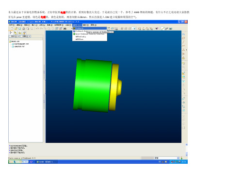
本人最近由于在做电控燃油系统,正好牵扯到电磁铁的计算,看到好像没人发过,于是就自己发一个,参考了AWB帮助的例题,有什么不正之处还请大家指教首先在proe里建模,绿色是电磁铁,黄色是衔铁,两者间隙0.28mm。
然后直接进入DM建立线圈和周围的空气。
在DM中新建一个plane,为的是建立线圈。
这个plane是基于图中绿色平面沿Z轴负向的一个距离-5.5mm
在新建的plane上新建草绘,然后画一个直径16.5的圆,这个圆是线圈中心尺寸
下一步从这个圆生成线体,如下图,选择草绘的圆
然后选择生成的线体,在winding body?中选择yes
设置线圈的圈数为71,高度为9mm,宽度为1mm,然后选view--cross section solid,隐藏衔铁和电磁铁可以看到线圈
建立包围的空气
形状选圆形,在merge parts?中选y es
保存DM文件,进入simulation,选择衔铁和电磁铁的材料为纯铁
网格划分在这里就不讲了,画完网格后,在new analy sis中选magnetostatic
然后选择conductor winding body,输入线圈中的电流值为12000mA
插入磁通平行条件,在磁通平行的scoping method 选name selection,在name selection中选open domain
在solve中插入磁感应强度和衔铁所受的磁力,在directional force/torque 的geometry中选择衔铁,方向选择Z轴
最后右键进行solve,由于材料B-H曲线是非线性的,因此计算时间有点长。
《电磁场有限元分析》课件

计算量大
对于大规模问题,有限元分析需要处理大量的 数据和计算,计算成本较高。
对初值和参数敏感
有限元方法对初值和参数的选择比较敏感,可 能会影响求解的稳定性和精度。
数值误差
有限元方法存在一定的数值误差,可能会导致结果的精度损失。
未来发展方向和挑战
高效算法
研究更高效的算法和技术,提高有限 元分析的计算效率和精度。
网格划分的方法
根据实际问题选择合适的网格类型,如四面体网 格、六面体网格等,并确定网格的大小和密度。
数据准备的内容
准备边界条件、初始条件、材料属性等数据,为 后续计算提供必要的数据支持。
有限元方程的求解和后处理
求解方法的选择
根据实际问题选择合适的求解方法,如直接求解法、 迭代求解法等。
求解步骤
将有限元方程组转化为线性方程组,选择合适的求解 器进行求解,得到各节点的数值解。
电磁场有限元分析简介
概述有限元分析的基本原理和方 法,包括离散化、近似函数、变
分原理等。
介绍电磁场有限元分析的基本步 骤,包括前处理、求解和后处理
等。
简要介绍电磁场有限元分析的常 用软件和工具,如ANSYS、 COMSOL Multiphysics等。
02
电磁场理论基础
麦克斯韦方程组
总结词
描述电磁场变化规律的方程组
详细描述
边界条件和初始条件是描述电磁场在边界和初始时刻的状态,对于求解电磁场问 题至关重要。
03
有限元方法基础
有限元方法概述
01
有限元方法是一种数值分析方法,通过将连续的物理域离散化 为有限数量的单元,利用数学近似方法求解复杂的问题。
02
该方法广泛应用于工程领域,如结构分析、流体动力学、电磁
workbench电机电磁场有限元分析分享资料

1
shown in the red boxes at
right.
2
Workshop
10/1/2004
8
ANSYS v9.0
Motor Analysis in the Workbench Environment
In the winding details pane, click on the cell to the right of “Center Plane”, then select Plane6 from the tree, then click apply (step 3 at right). This positions/orients the windings so that predefined plane6 is the winding midplane.
Enclosure name changed to “Air” Shape: Cylinder Alignment: Automatic Cushion: 8 mm Target: All Bodies Merge Parts?: Yes
Workshop
10/1/2004
5
ANSYS v9.0
Motor Analysis in the Workbench Environment
these default values.
Workshop
10/1/2004
4
ANSYS v9.0
Motor Analysis in the Workbench Environment
Click on the individual entries in the right hand column of the details pane and edit them as shown below.
Ansys Workbench有限元分析
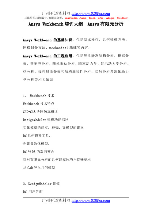
Ansys Workbench培训大纲 Ansys有限元分析Ansys Workbench的基础知识,包括基本操作、几何建模方法、网格划分方法、mechanical基础等内容;Ansys Workbench的工程应用,包括线性静态结构分析、模态分析、谐响应分析、随机振动分析、瞬态动力学、显示动力学分析、热分析、线性屈曲分析和结构非线性分析、接触分析及流体动力学分析等相关知识1. Workbench技术Workbench技术特点CAD-CAE协同仿真概述DesignModeler建模功能综述实体模型的建立,板壳、梁模型的建立DM几何修补工具,创建参数化模型,DM与DS的双向整合针对有限元分析的几何建模技巧与特殊要求从CAD导入几何模型2.DesignModeler建模DM 用户界面DM 草图模式DM 3D几何体DM高级3D几何体DM 概念建模DM 参数化模型3.DesignSimulation基本架构和分析流程DS基础DS通用前处理: 几何模型导入, 接触,网格划分,命名选择,坐标系DS高质量的有限元网格划分技术和使用技巧DS结构静力线性分析的基本流程和使用技巧DS各种工程载荷和边界条件的处理方法DesignSimulation的非线性概述材料、几何、接触非线性的基本过程与应用技巧4.DesignSimulation基本架构和分析流程DS结果后处理:查看,显示,输入结果,结果组合DS如何提高有限元分析的精度DS与CAD软件的交互性及参数传递DS通过参数管理器和多工况多方案的优化方法快速完成分析5.DesignSimulation的工程分析类型疲劳分析动力学分析:瞬态等分析基本过程与技巧DesignSimulation稳态热分析:热分析基础,基本的热传递分析,热分析模式,实例分析:建模,求解及后处理DesignSimulation瞬态热分析:时间与载荷步,子步及平衡迭代,收敛准则,初始温度,阶跃及渐变载荷输出控制,查看瞬态分析结果,耦合场分析:热应力分析有限元基本概念把一个原来是连续的物体划分为有限个单元,这些单元通过有限个节点相互连接,承受与实际载荷等效的节点载荷,并根据力的平衡条件进行分析,然后根据变形协调条件把这些单元重新组合成能够整体进行综合求解。
ANSYSWorkbench电磁场分析例子共38页

ANSYS, Inc. Proprietary
Contents
Workbench Electromagnetics
– Workbench Emag Roadmap
– Design Modeler
• Enclosure Symmetry • Winding bodies • Winding Tool
• Workbench v9.0 is the first release with electromagnetic analysis capability. – Support solid and stranded (wound) conductors – Automated computations of force, torque, inductance, and coil flux linkage. – Easily set up simulations to compute results as a function of current, stroke, or rotor angle.
– Up to 3 three symmetry planes can be specified. – Full or partial models can be included in the Enclosure. – During the model transfer from DesignModeler to Simulation, the enclosure feature with symmetry planes forms two kinds of named selections:
– Winding Bodies: Used to represent wound coils for source excitation. The advantage of these bodies is that they are not 3D CAD objects, and hence simplify modeling/meshing of winding structures.
电磁场问题的有限元分析

ANSYS电磁场分析首先求解出电磁场的磁势和电势, 然后经后处理得到其他电磁场物理量,如磁力线分布、磁 通量密度、电场分布、涡流电场、电感、电容以及系统能 量损失等
● 电力发电机 ● 变压器 ● 电动机 ● 天线辐射 ● 等离子体装置
9.1 电磁场基本理论
(4)ANSYS电磁场分析简介 2. ANSYS电磁场分析方法 (2)建立分析模型。 在建立几何模型后,对求解区域用选定的单元进行划分, 并对划分的单元赋予特性和进行编号。 单元划分的疏密程度要根据具体情况来定,即在电磁 场变化大的区域划分较密,而变化不大的区域可划分得稀 疏些。 (3)施加边界条件和载荷。 (4)求解和后处理。
过滤图形用户界面进入电磁场 分析环境。在ANSYS软件的 Multiphysics模块中,执行:Main Menu>Preferences,在弹出的对话 框中选择多选框“Magnetic-Nodal” 后,单击[OK]。
9.2 二维静态磁场分析
(2)二维静态磁场分析实例 (2) 建立模型 ①生成大圆面:Main Menu>Preprocessor>Modeling>Create>Area >Circle>By Dimensions弹出如对话框,在对 话框中输入大圆的半径“6”.然后单击 [OK]。 ②生成小圆: MainMenu>Preprocessor>Modeling>Create>Areas>Ci rcle>Solid Circle,弹出一个对话框,在“WP X”后面 输入“1”,在“Radius”后面输入“2”,单击[OK], 则生成第第二个圆。 ③布尔操作: MainMenu>Preprocessor>Modeling>Cr eate>Booleans>Overlap>Area,在弹出 对话框后,单击[Pick All]。
ANSYSWorkbench电磁场分析例子ppt课件

© 2004 ANSYS, Inc.
ANSYS, Inc. Proprietary
Enclosure Symmetry
•Feature: The Enclosure feature now supports symmetry models when the enclosure shape is a box or a cylinder: • Up to 3 three symmetry planes can be specified. • Full or partial models can be included in the Enclosure. • During the model transfer from DesignModeler to Simulation, the enclosure feature with symmetry planes forms two kinds of named selections: • Open Domain • Symmetry Plane
• Benefits: Very easy to use, rapid creation of coil windings.
© 2004 ANSYS, Inc.
ANSYS, Inc. Proprietary
Winding Bodies
Tangent orientation vector (blue arrow) defines direction of current.
• Coils may have different radii between IN & OUT slots • Multiple coils may be stacked in the same slot
- 1、下载文档前请自行甄别文档内容的完整性,平台不提供额外的编辑、内容补充、找答案等附加服务。
- 2、"仅部分预览"的文档,不可在线预览部分如存在完整性等问题,可反馈申请退款(可完整预览的文档不适用该条件!)。
- 3、如文档侵犯您的权益,请联系客服反馈,我们会尽快为您处理(人工客服工作时间:9:00-18:30)。
Workshop
10/1/2004
6
ANSYS v9.0
Motor Analysis in the Workbench Environment
In the tree, open the item “1 Part, 5 Bodies” by clicking on the “+” symbol to the left of it. Do the same with the item labeled “part” that appears below it. Note that the single part in the model consists of 5 individual bodies (stator, rotor, magnet1, magnet2, and “solid”).
bodies except “Solid”. For
example, suppression of the
2
to browse for the file.
1
Workshop
3
10/1/2004
10
ANSYS v9.0
Motor Analysis in the Workbench Environment
Once the file is read in, make the following additional changes in the winding details pane:
The image can be dynamically rotated as follows:
1) Position the mouse cursor on the display
2) Hold down the middle mouse button (MMB)
3) Move the mouse cursor
After editing the details, right click on “Air” in the tree. In the drop down list that appears, left click on “Generate”. This will create a cylindrical volume of magnetic domain in which to immerse the imported parts.
2
in this manner.
10/1/2004
Workshop
7
ANSYS v9.0
Motor Analysis in the Workbench Environment
Use the Winding Tool Editor to
bring up the “winding details”
and “winding table” panes
Conductor A: 55 A 0
Conductor B: 55 A 120
1
Conductor C: 55 A 240
Workshop
2
10/1/2004
15
ANSYS v9.0
Motor Analysis in the Workbench Environment
Prepare to define magnetic flux parallel boundaries on the exterior of the modeled domain as shown at right. 2
• FD2: Slot Angle => 22.5
• Clash Detection? => Yes
Setting clash detection to “yes” will bring up another row called “Bodies for Clash Detection” in the winding details pane. Click the cell to the right, highlight “rotor” in the tree, and click Apply. This will trigger a check for interference between the defined windings and the rotor stack.
(winding.txt) is in the local
working directory. Read the
table as shown at right. Click
the cell to the right of “winding
Table File” in the winding
details pane and click on “…”
10/1/2004
Workshop
3
ANSYS v9.0
Motor Analysis in the Workbench Environment
1) Bring up the enclosure tool as
shown at right. This will be used to automatically create a
Workshop
1
2
10/1/2004
2
ANSYS v9.0
Motor Analysis in the Workbench Environment
You should see an end view of the motor geometry. Using the left mouse button (LMB) click on the blue dot adjacent to the triad in the lower right corner of the plot. This should result in the isometric view shown at right.
Right click on “solid” and in the
drop down menu, request that 1 it be hidden in the display.
Note that the display of any
individual bodies may be
either suppressed
Workshop
10/1/2004
13
ANSYS v9.0
Motor Analysis in the Workbench Environment
Now click on the Project tab and
choose “New Simulation”
1
2
Workshop
10/1/2004
14
Workshop
10/1/2004
12
ANSYS v9.0
Motor Analysis in the Workbench Environment
One nice way to visualize the windings is to right click on rotor in the tree and choose “Hide All Other Bodies” in the drop down list. Then, in the tree, click on any of the 6 individual coils comprising the winding (A.1, A.2, B.1, B.2, C.1, C.2). For example, the location of coil A.1 is shown below. 1
2
Workshop
3: Click “Apply”
1
10/1/2004
9
ANSYS v9.0
Motor Analysis in the Workbench Environment
A winding table text file
containing information
describing the rotor coils
1
mesh of the magnetic domain
between and surrounding the
imported geometry
2 2) Note the details that appear in
the lower left pane after this
selection is made. We will edit
these default values.
Workshop
10/1/2004
4
ANSYS v9.0
Motor Analysis in the Workbench Environment
Click on the individual entries in the right hand column of the details pane and edit them as shown below.
1
Workshop
10/1/2004
16
ANSYS v9.0
Motor Analysis in the Workbench Environment
In order to more easily select the
external surfaces of the
modeled domain, suppress all
Enclosure name changed to “Air” Shape: Cylinder Alignment: Automatic Cushion: 8 mm Target: All Bodies Merge Parts?: Yes
Workshop