简单温度控制完整程序
温度控制系统具体源程序

/******************************************************************/
/* 向CH451传输数据 */
ch451_din=1;
ch451_load=1;
ch451_dout=1;
#ifdef USE_KEY
IT1=0; //设置下降沿触发
IE1=0; //清中断标志
#include<reg52.h> //包含头文件,一般情况不需要改动,头文件包含特殊功能寄存器的定义
#include<math.h>
#include<INTRINS.H>
#define uchar unsigned char
#define uint unsigned int
#define CH451_LEFTCYC 0x0301 //设置移动方式-左循
#define CH451_RIGHTMOV 0x0302 //设置移动方式-右移
#define CH451_RIGHTCYC 0x0303 //设置移动方式-右循
//******************************************************
void Set_temp(void) //设定保温点
{ unsigned char i;
ch451_write(CH451_DIG0|showtemp[0]);//显示原来设定温度
void delay1(uchar MS);
unsigned int ReadTemperature(void);
恒温控制算法 c语言版
恒温控制算法c语言版全文共四篇示例,供读者参考第一篇示例:恒温控制算法是一种用于调节系统温度的智能控制算法。
该算法通过采集环境温度数据,并根据设定的目标温度进行计算,实现自动调节系统的输出控制信号,从而维持系统温度稳定在设定值附近。
在工业生产、实验室研究和家用电器等领域都广泛应用了恒温控制算法,以确保系统稳定性和高效性。
C语言是一种通用的编程语言,具有良好的可移植性和高效性。
在实际应用中,恒温控制算法通常会在嵌入式系统或工控系统中实现,而使用C语言编写程序是一种常见的选择。
下面我们将介绍一种基于C 语言的恒温控制算法实现方式。
我们需要定义一些基本的变量和常数。
我们需要设置目标温度值、温度传感器读取间隔、控制信号输出范围等。
接下来,我们将使用C语言编写一个基本的恒温控制算法框架,示例如下:```c#include <stdio.h>#include <stdlib.h>// 定义温度传感器读取间隔,单位为秒#define SENSOR_INTERVAL 1// 定义目标温度值#define TARGET_TEMPERATURE 25// 定义控制信号输出范围#define OUTPUT_MIN 0#define OUTPUT_MAX 100while(1) {// 读取温度传感器数据currentTemperature = readTemperatureSensor();// 计算控制信号outputSignal =calculateControlSignal(currentTemperature);// 等待传感器读取间隔delay(SENSOR_INTERVAL);}return 0;}int calculateControlSignal(int temperature) {// 根据当前温度和目标温度计算控制信号int error = TARGET_TEMPERATURE - temperature;int controlSignal = OUTPUT_MAX * error / TARGET_TEMPERATURE;return controlSignal;}void outputControlSignal(int signal) {// 输出控制信号,此处可与系统的执行机构进行通信实现控制printf("Control signal: %d\n", signal);}void delay(int seconds) {// 延时函数,单位为秒sleep(seconds);}```上述代码实现了一个简单的基于C语言的恒温控制算法。
温度控制C程序

fm=1;
red=1;
green=0;
}
if(b2==0xbf)
{
if(temp>=xiaxian)
temp=xiaxian;
if((temp==xiaxian)&&b2==0xbf)
{
dsreset();
delay(1);
tempwritebyte(0xcc); // 写跳过读ROM指令
tempwritebyte(0x44); //写温度转换指令
}
uint get_temp() //读取寄存器中存储的温度数据
{
uchar i;
i=t/100;
display(0,i);
i=t%100/10;
display(1,i+10);
i=t%100%10;
display(2,i);
}
void tht1()
{
dsreset();
delay(1);
}
else
{
ds=0; //写0
i=8;while(i>0)i--;
ds=1;
i++;i++;
}
}
}
void tempchange(void) //DS18B20开始获取温度并转换
uchar num,num1,num2,num3;
uint temp,shangxian,xiaxian,aa,bb,ee; //定义温度上下限值
uint flag1,b1,t,t1,f,f1,b2,n;
unsigned char code table[]={0xc0,0xf9,0xa4,0xb0,0x99,0x92,0x82,0xf8,0x80,0x90,0xff,0xbf};
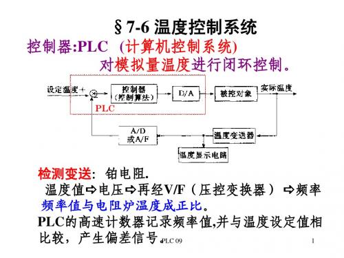
PLC温度控制

基于组态软件的S7-200 PLC温度控制系统中文摘要随着自动化水平不断提高,人们对自动化的要求也不断提高。
近几年,飞速发展的计算机技术在各行各业得到广泛应用。
但是,以之相对应,传统的工业控制软件有开发周期长,重复使用率低,价格高,修改难等缺点。
随着越来越多的自动化设备不断得到应用,人们对工业控制软件的要求也不断提高,传统的工业控制软件已无法满足用户的要求。
如何方便快捷的使用工业控制软件设计出灵活有效的自动控制系统已成为一个很重要的课题。
本设计以S7-200 PLC为核心,向上,通过PPI通信和上位机通讯;向下,通过模拟量输入输出模块EM235,对温度对象采样与输出控制。
在上位机,使用组态软件MCGS绘出工艺流程、动画效果等所需的组态界面;通过变量与动画对象的连接,使动画效果与实际变量相对应,这样可以很方便的从组态界面上看到系统实际情况并控制PLC的各个参数。
在温度采样上,使用PT100热电阻进行采样,使用脉宽调制电路对输出电压进行控制,进而形成完整的温度控制系统。
本文分别通过硬件的选择、设计、使用,软件的选择、编写等方面详细介绍系统各个模块的原理、设计和使用。
实验证明,以PLC作为控制器的核心,使用组态软件作为上位机,控制PLC,再通过PLC编程控制温度对象,这种设计方式方式可以方便快捷灵活的设计出符合要求的控制系统。
关键字:MCGS组态软件,PPI通讯,PLC ,温度控制系统S7-200 PLC Temperature Control System Based onConfiguration SoftwareAbstractWith the continuous development of the industral automatization,it set higher requirements for the automatics.These years, computer technology have been developing rapidly and are widely used in every walk of life.In the other hand,however,the traditional industry controlling software bring with it critical shortcomings such as long development cycle,low reusability,high price and immobility.As more and more automatic equipments are applied and the requirements for industrial control software are higher and higher,the traditional industry controlling software can’t meet customers’ dema nd any more.How to design a flexible and effective automatic control system fastly and conveniently by using industrial control software has become a very important topic.This thesis focus on S7-200 PLC,which communicating,upward,with upper monitor through PPI,and also sampling temperature and outputing control single downward through Analog I/O module--EM235.Necessary configuration interface such as software process and animation effects are accomplished by using MCGS configuration software in upper monitor;Through connecting variable to animation effects,making animation effects the counterpart of actual variable,thus make it convenient to see actual situation and to control each parameter of PLC in configuration interface.In term of temperature sampling,thermal resistor PT100 are used to take sample,PWM are used to control output voltage,so that a complete temperature control system are formed.This Thesis introduce the principle,design, application of the each system module in detail,which including the type selection,design and application of the hardware,and the selection and writing of the software.Experiments prove that the design solution which using PLC as control core to control temperature object,configuration software as upper monitor to control PLC,could achieve a desirable control system conveniently, quickly and flexiblely.Key words: MCGS configuration software, PPI communication, PLC, temperature control system目录中文摘要 (I)ABSTRACT................................................................................................................................ I I 目录. (III)第1章绪论 (1)1.1温度控制系统研究背景 (1)1.2PLC概况 (2)1.2.1 PLC的定义 (2)1.2.2 PLC的特点 (2)1.2.3 PLC的国内外状况 (3)1.2.4 PLC未来展望 (3)1.3组态软件 (4)1.3.1 组态软件背景 (4)1.3.2 监控组态软件的最新发展情况 (4)1.3.3 组态软件的未来 (6)1.4研究主要内容 (6)第2章硬件电路的设计 (8)2.1系统的组成 (8)2.1.1 控制系统结构图 (8)2.1.2 系统的硬件组成 (9)2.2硬件的连接 (10)第3章PLC程序设计 (12)3.1系统的控制要求 (12)3.2系统工作过程 (12)3.3系统开关量的分配 (14)3.4系统使用内存分配 (15)3.5S7-200PLC自带PID模块设定 (16)3.5.1 PID简介 (16)3.5.2 S7-200 PLC自带PID的设置 (17)3.6PLC程序设计 (18)3.6.1 程序流程图 (18)3.6.2 主程序 (18)3.6.3 子程序 (23)3.7S7-200PLC PPI通讯设置 (24)第4章MCGS组态软件设计 (26)4.1MCGS组态软件概述 (26)4.1.1 MCGS嵌入版组态软件的主要功能 (26)4.1.2 MCGS 软件结构 (28)4.2监控系统功能设计 (29)4.2.1 组态软件的设计要求 (29)4.2.2 组态功能设计 (29)4.3MCGS组态界面设计 (30)4.4设备窗口 (34)4.5变量定义及连接 (36)4.5.1 实时数据库定义 (36)4.5.2 变量连接 (36)4.6运行策略 (37)第5章系统测试 (39)5.1组态测试 (39)5.2系统测试 (41)5.2.1 各种参数的响应曲线图 (41)5.2.2 曲线分析 (44)总结 (45)参考文献 (46)致谢............................................................................................................... 错误!未定义书签。
C语言编写PID温度控制器程序

C语言编写PID温度控制器程序姓名:况武(07421236)班级:自二系别:通控系#include <stdio.h>#include<math.h>struct _pid {int pv; /*integer that contains the process value*/int sp; /*integer that contains the set point*/float integral;float pgain;float igain;float dgain;int deadband;int last_error;};struct _pid warm,*pid;int process_point, set_point,dead_band;float p_gain, i_gain, d_gain, integral_val,new_integ;;/*------------------------------------------------------------------------pid_initDESCRIPTION This function initializes the pointers in the _pid structureto the process variable and the setpoint. *pv and *sp areinteger pointers.------------------------------------------------------------------------*/void pid_init(struct _pid *warm, int process_point, int set_point){struct _pid *pid;pid = warm;pid->pv = process_point;pid->sp = set_point;}/*------------------------------------------------------------------------pid_tuneDESCRIPTION Sets the proportional gain (p_gain), integral gain (i_gain),derivitive gain (d_gain), and the dead band (dead_band) ofa pid control structure _pid.------------------------------------------------------------------------*/void pid_tune(struct _pid *pid, float p_gain, float i_gain, float d_gain, int dead_band){pid->pgain = p_gain;pid->igain = i_gain;pid->dgain = d_gain;pid->deadband = dead_band;pid->integral= integral_val;pid->last_error=0;}/*------------------------------------------------------------------------pid_setintegDESCRIPTION Set a new value for the integral term of the pid equation.This is useful for setting the initial output of thepid controller at start up.------------------------------------------------------------------------*/void pid_setinteg(struct _pid *pid,float new_integ){pid->integral = new_integ;pid->last_error = 0;}/*------------------------------------------------------------------------pid_bumplessDESCRIPTION Bumpless transfer algorithim. When suddenly changingsetpoints, or when restarting the PID equation after anextended pause, the derivative of the equation can causea bump in the controller output. This function will helpsmooth out that bump. The process value in *pv shouldbe the updated just before this function is used.温度PID控制的C语言程序?------------------------------------------------------------------------*/void pid_bumpless(struct _pid *pid){pid->last_error = (pid->sp)-(pid->pv);}/*------------------------------------------------------------------------pid_calcDESCRIPTION Performs PID calculations for the _pid structure *a. This function uses the positional form of the pid equation, and incorporates an integral windup prevention algorithim. Rectangular integration is used, so this function must be repeated on a consistent time basis for accurate control.RETURN V ALUE The new output value for the pid loop.USAGE #include "control.h"*/float pid_calc(struct _pid *pid){int err;float pterm, dterm, result, ferror;err = (pid->sp) - (pid->pv);if (abs(err) > pid->deadband){ferror = (float) err; /*do integer to float conversion only once*/pterm = pid->pgain * ferror;if (pterm > 100 || pterm < -100){pid->integral = 0.0;}else{pid->integral += pid->igain * ferror;if (pid->integral > 100.0){pid->integral = 100.0;}else if (pid->integral < 0.0) pid->integral = 0.0;}dterm = ((float)(err - pid->last_error)) * pid->dgain;result = pterm + pid->integral + dterm;}else result = pid->integral;pid->last_error = err;return (result);}void main(void){float display_value;int count=0;pid = &warm;// printf("Enter the values of Process point, Set point, P gain, I gain, D gain \n");// scanf("%d%d%f%f%f", &process_point, &set_point, &p_gain, &i_gain, &d_gain);process_point = 30;set_point = 40;p_gain = (float)(5.2);i_gain = (float)(0.77);d_gain = (float)(0.18);dead_band = 2;integral_val =(float)(0.01);printf("The values of Process point, Set point, P gain, I gain, D gain \n");printf(" %6d %6d %4f %4f %4f\n", process_point, set_point, p_gain, i_gain, d_gain);printf("Enter the values of Process point\n");while(count<=20){scanf("%d",&process_point);pid_init(&warm, process_point, set_point);pid_tune(&warm, p_gain,i_gain,d_gain,dead_band);pid_setinteg(&warm,0.0); //pid_setinteg(&warm,30.0);//Get input value for process pointpid_bumpless(&warm);// how to display outputdisplay_value = pid_calc(&warm);printf("%f\n", display_value);//printf("\n%f%f%f%f",warm.pv,warm.sp,warm.igain,warm.dgain); count++;}}。
温度控制系统
其中: 调节器第n 次采样输出值; 其中:u (n) :调节器第 次采样输出值;
e(n) :第 n 次采样的偏差值; 次采样的偏差值;
e(n − 1) :第 (n-1)次采样的偏差值; 次采样的偏差值; 次采样的偏差值
PLC 09 3
K p :比例系数; 比例系数; 比例系数 Ts K i = K p :积分系数;(教材式 7- 2 有误) 积分系数;( ;(教材式 有误) Ti Td K d = K p :微分系数。 微分系数。 Ts
1 u (t ) = K p [e(t ) + Ti de(t ) ∫0 e(t )dt + Td dt ]
t
2
PLC 09
PID算法的传递函数 算法的传递函数
G ( s) =
U ( s) 1 = K p [1 + + Td s ] E ( s) Ti s
2.数字PID控制算法 .数字 控制算法
位置式算法: 位置式算法 设采样周期为T 离散化连续PID算法 设采样周期为 s,离散化连续 算法 求和代替积分,差分代替微分) (求和代替积分,差分代替微分) Ts n Td u (n) = K p {e(n) + ∑ e( j ) + [e(n) − e( n − 1)]} Ti j = 0 Ts = K p e(n) + K i ∑ e( j ) + K d ∆e(n)
0.8 y (kT − T ) + 0.2 y (kT )
表明: 表明:在滤波结果中起主要作用的是 y(kT−T)
是前一时刻的滤波值而不是当前时刻的采样值。 前一时刻的滤波值而不是当前时刻的采样值。 而不是当前时刻的采样值
y 例如: 相差1倍 例如: (kT − T ) = 0.5, y ( kT ) = 1, 相差 倍; y (kT ) = 0.8 y (kT − T ) + 0.2 y (kT ) = 0.6
西门子PLC温度控制示例
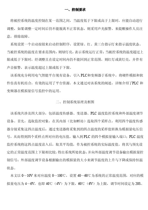
一、控制要求将被控系统的温度控制在某一范围之间,当温度低于下限或高于上限时,应能自动进行调整,如果调整一定时间后仍不能脱离不正常状态,则采用声光报警,来提醒操作人员注意,排除故障。
系统设置一个启动按钮来启动控制程序,设置绿、红、黄三台指示灯来指示温度状态。
当被控系统的温度在要求范围内,则绿灯亮,表示系统运行正常;当被控系统的温度超过上限或低于下限时,经调整且在设定时间内仍不能回到正常范围,则红灯或黄灯亮,并伴有声音报警,表示温度超过上限或低于下限。
该系统充分利用电气智能平台现有设备,引入PLC和变频器于系统中,将硬件模拟和软件仿真有机结合,有效的运用了平台资源。
本文通过对该系统的阐述,详细介绍了P LC和变频器在模拟量信号监控中的运用。
二、控制系统原理及框图该系统共涉及四大部分,包括温度传感器、变送器、PLC温度监控系统和外部温度调节设备。
首先,选取监控对象,在其内部(比如孵坊)选取四个采样点,利用四个温度传感器分别采集这四点温度后;通过变送器将采集到的四点温度的采样值转换为模拟量电压信号,从而得到四个采样点所对应的电压值,输入到PLC的四个模拟量输入端口;PLC温度监控系统将这四点温度读入后,取其平均值,作为被控系统的实际温度值,将其与预先设定的正常温度范围上下限相比较,得出系统所处状态,并向外部温度调节设备输出模拟量控制信号;外部温度调节设备根据输出的模拟量的大小来调节温度的上升与下降或保持恒温状态。
本文以0~10V来对应温度0~100℃,设置40~60℃为系统的正常温度范围,对应的模拟量电压为4~6V,也即40℃(4V)为下限,60℃(6V)为上限,调节时间设定为20S。
其中,50℃(5V)为我们的温度(电压)基准值。
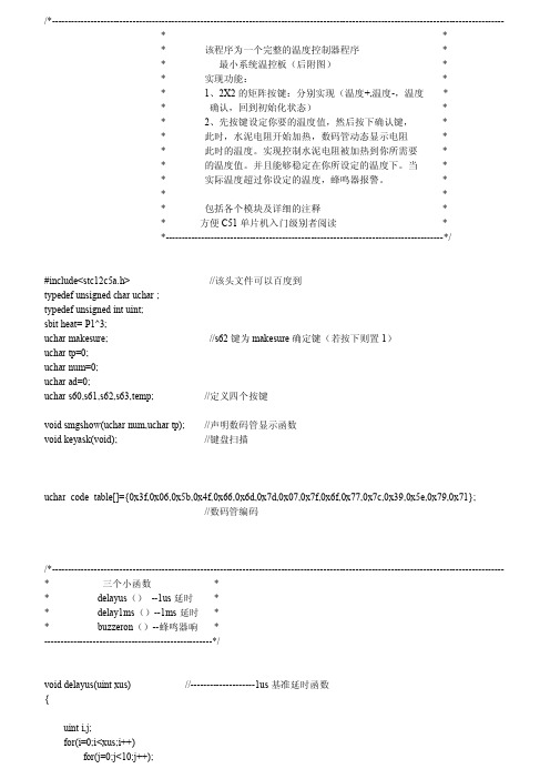
C51单片机实例温控程序(各模块详解附图
*
*
实际温度超过你设定的温度,蜂鸣器报警。
*
*
*
*
包括各个模块及详细的注释
*
*
方便 C51 单片机入门级别者阅读
*
*--------------------------------------------------------------------------------------*/
#include<stc12c5a.h> typedef unsigned char uchar ; typedef unsigned int uint; sbit heat= P1^3; uchar makesure; uchar tp=0; uchar num=0; uchar ad=0; uchar s60,s61,s62,s63,temp;
/*--------------------------------------------------------------------------------------------------------------------------------------------
*
*
*
该程序为一个完整的温度控制器程序
0x3e,0x3d,0x3d,0x3c,0x3b,0x3b,0x3a,0x39,0x38,0x38,0x37,0x36,0x36,0x36,0x35,0x35,
0x34,0x33,0x33,0x32,0x32,0x31,0x31,0x30,0x30,0x2f,0x2f,0x2e,0x2e,0x2d,0x2d,0x2c,
0x10,0x0f,0x0f,0x0e,0x0e,0x0e,0x0d,0x0d,0x0c,0x0c,0x0b,0x0b,0x0b,0x0a,0x0a,0x09,
- 1、下载文档前请自行甄别文档内容的完整性,平台不提供额外的编辑、内容补充、找答案等附加服务。
- 2、"仅部分预览"的文档,不可在线预览部分如存在完整性等问题,可反馈申请退款(可完整预览的文档不适用该条件!)。
- 3、如文档侵犯您的权益,请联系客服反馈,我们会尽快为您处理(人工客服工作时间:9:00-18:30)。
P2 = dat;
ep = 1;
ep = 0 ;
} void lcd_init()
{//LCD初始化设定
//function set
//function set
//display on/off
〃除LCD的显示内容
//entry mode set
delay⑴;
/*函数名称:display()
BOOL lcd_bz()
rs = 0 ; rw = 1 ; ep = 1;result = (BOOL)(P2&0x80); ep = 0 ;
return result;
} void lcd_wcmd(uchar cmd)
{//写入指令数据到LCD
while(lcd_bz());
rs =
:0;
rw:
void lcd_wcmd(uchar);
BOOL lcd_bz();
void lcd_pos(uchar);
void lcd_wdat(uchar);
void display(uchar,uchar *);
void lcd_init();
void longdelay(uchar s);
void keyscan(void);
delay2(80);〃精确延时大于480us
DQ = 1;〃拉高总线
delay2(10);
x=DQ;〃稍做延时后如果x=0则初始化
成功x=l则初始化失败
delay2(5);
DQ=1;
//return (x);
}
^2^ <2><2^ ^2> <S> ^2>^2^ ^2> ^2> ^2^ <2> ^2> ^S><2> ^2>^2^ ^2> <2^ ^S> ^2^ <2> ^2> <2^ ^2> <S> ^2>
unsigned int setl=30,set2=10;
unsigned char flag=O;
sbit DQ =P1A7;〃定义通信端口
sbit fengmingqi=P 1A1;
sbit jidianqi=PlA5;
codeuchar
mayuan[]={,0Vl\,2,;3,;475,;6,;7,;8,;9,};
f rj^ rj> rjw rj> rjw rj> rj>/
〃读一个字节
unsigned char ReadOneChar(void) {
unsigned char i=0;
unsigned char dat = 0;
for (i=8;i>0;i—)
{
DQ = 1;
delay2(5);
DQ = 0; //给脉冲信号
}
void delayl(uchar a) {
while(a-);
} void delay2(unsigned int i)〃延时函数
{
while(i—);
}
void Imt_DS18B20(void)
{
unsigned char x=0;
DQ = 1; //DQ复位
delay2(8);〃稍做延时
DQ = 0;〃单片机将DQ拉低
lcd_pos(pos);
for(i=0 ;i<9;i++)
lcd_wdat(*q); q++;
}
void putchar(uchar weizhi,uchar da)
{
delay (2);
lcd_pos(weizhi);
lcd_wdat(da);
}
〃延时函数
uchar i;
while(ms—)
{
for(i = 0 ; i<250;i++);
=0;
ep =
=0;
P2:
=cmd ;
ep =
=1;
ep =
=0;
void lcd_pos(uchar pos)
{〃设定显示位置
lcd_wcmd(pos I 0x80);
}
void lcd_wdat(uchar dat)
{〃写入字符显示数据到LCD
while(lcd_bz());
rs = 1 ; rw = 0 ;
Jr|> <l> rj>rj> rj> r|> rj> rj> rj>r|> r|> rj> rj>r|> rj> e^> rj> rj>rj> rj> r|> rj> rj>
<f> <9><f> <f> <Y>k{><f> <f><f> <9>k|>%f><f> <f> <Y>
rjw rjw rjwrj> rjw rjw rjwrj> rjw rjw rjwrj> rjw rjw rjwrj> rjw rjw rjwrj> r|>
<f> <f> <f> <f>
rj>rj> rj> rj>rj>rj> rj> rj>rj>rj> rj> rj>rj>rj> rj> rj>rj>rj> rj> rj> rj>
code uchar aa[]={Hwendu is:''};
code uchar bb[]={nsheding:
typedef bit BOOL ;
unsigned char k,dat_wr[8],dat_rd[8];
void putchar(uchar weizhi,uchar da); void delay(uchar);
简单温度控制完整程序
#include<reg52.h>
#include <intrins.h> #define uchar unsigned char #define uint unsigned int sbit rs = P3A4 ;
sbit rw = P3A5 ;
sbit ep = P3A7 ;
dat»=l;
DQ = 1;//给脉冲信号
if(DQ)
datl=0x80;
delay2(5);
DQ = 1;
return(dat);
}
^2^ ^2^ ^2> <2>^2> ^S><2> ^2^ ^2^ ^2^ ^2^ <2> <2^ ^2> ^2>^S> ^2>
/ rj> rj> rj> <j> rj> rj> rj> rj> rj> e^> rj^ rj> rj> rj^ rj> rj> rj^ rj> rj> rj> rj> rj> rj> <j> rj> rj> rj> rj> rj> e^> rj^ rj> rj>
功能:在LCD±显示数组的数据调用:lcd_wcmd()9lcd_pos()
入口参数:pos写入的位置,q指向要写入的数 据所在的数组 返回值:无
*/
void display(uchar pos, uchar *q) {
uchar i;
//lcd_wcmd(0x01) ; //clear
//delay(lO);