LED显示屏调试软件NovaLCT多媒体播放器用户指南
LED播放器软件使用说明书

LED播放器软件使用说明书目录:第一章:软件介绍第二章:操作指南一节:安装与卸载二节:LED播放器界面三节:菜单功能详解第三章:几项重要设置一节:体育比分设置二节:定时播放设置三节:后台播放四节:软件设置和用户设置五节:远程控制设置第四章:节目组成一节:节目组成和制作区域第五章:制作节目文件一节:新建节目二节:制作图文节目三节:制作文本节目四节:制作单行文本节目五节:制作静止文本节目六节:制作表格节目七节:制作计时节目八节:制作数据库节目九节:制作VCD/DVD节目十节:制作外部程序节目十一节:制作视频输入节目十二节:制作日期/时间节目第六章:注意事项和常见问题与解答第一章软件介绍LED播放器是我公司自主研发的适用于各LED显示屏节目编辑播放的一款软件。
使用简单,易学。
功能全面。
可以播放多种文件,文本,WORD,EXCEL,各种格式图片文件,视频文件。
多种时间显示模式。
适用win98/2000/xp计算机操作系统。
第二章操作指南第一节.安装与卸载2.1.1.将公司附带产品的光盘放入计算机光驱,会弹出软件安装界面。
如图1-1。
拖动鼠标选择并双击led播放器安装程序(注:LED播放器安装程序里包含LED控制卡驱动程序)。
按照安装提示步骤操作完成并重起电脑。
安装成功后计算机桌面和开始—程序—LED显示屏,出现此图标。
双击此图标打开LED 播放器。
卸载软件,卸载的时候从新运行本软件的安装程序,在安装向导里出现3个选项为:第一个自动安装,第二个修复,第三个卸载。
鼠标点击卸载会自动删除本软件的所有程序。
也可以在控制面版中选择[添加/删除程序]快速卸载。
第二节.LED播放器操作界面2.2.1.打开播放器会出现两个组合部分,播放窗口为黑色区域是LED大屏幕显示区域。
第2部分为操作控制窗口如图示2-1。
2.2.2.操作控制窗口由控制工具菜单和节目编辑信息区域组成如图示2-2.。
在图示红线上面部分是控制工具菜单,在红线下面部分是节目编辑信息区域。
诺瓦科技LED显示屏控制软件SmartLCT用户手册

版权所有© 西安诺瓦电子科技有限公司2018。
保留一切权利。
非经本公司书面许可,任何单位和个人不得擅自摘抄、复制本文档内容的部分或全部,并不得以任何形式传播。
商标声明是诺瓦科技的注册商标。
声明欢迎您选用西安诺瓦电子科技有限公司(以下简称诺瓦科技)的产品,如果本文档为您了解和使用产品带来帮助和便利,我们深感欣慰。
我们在编写文档时力求精确可靠,随时可能对内容进行修改或变更,恕不另行通知。
如果您在使用中遇到任何问题,或者有好的建议,请按照文档提供的联系方式联系我们。
对您在使用中遇到的问题,我们会尽力给予支持,对您提出的建议,我们衷心感谢并会尽快评估采纳。
SmartLCT 显示屏配置软件用户手册更新记录更新记录SmartLCT 显示屏配置软件 (ii)更新记录 (ii)目录 (iii)用户手册目录目录1 简介 (1)系统架构...................................................................................................................................................... 2配置列表 (2)软件安装 (3)注意事项 (32)界面介绍 (4)3 语言设置 (6)4 离线操作 (7)界面介绍......................................................................................................................................................7新建项目 ......................................................................................................................................................9显示屏配置 ................................................................................................................................................104.3.1 添加箱体 (10)4.3.2 配置箱体走线 (11)12发送配置信息 ............................................................................................................................................13其他操作 ....................................................................................................................................................144.5.1 添加设备 (14)4.5.2 热备份 (14)5 在线操作 (17)界面介绍 (17)新建项目 (21)显示屏配置 (22)5.3.1 添加箱体 (22)5.3.2 配置箱体走线 (23)亮暗线调节 (23)5.4.1 界面介绍 (23)5.4.2 亮暗线参数调节 (25)SmartLCT 显示屏配置软件用户手册目录多批次调节................................................................................................................................................26监控 ...........................................................................................................................................................275.6.1 实时监控 (28)5.6.2 误码率检测 (29)5.6.3 版本信息 (29)5.6.4 监控配置.................................................................................................................................................29发送配置信息 ............................................................................................................................................30V-Sender (30)5.8.1 如何进入V-Sender? (30)5.8.2 工具栏功能介绍 (31)5.8.3 添加设备 (31)325.8.6 模板设置 (33)5.8.7 设备属性 (33)5.8.8 画中画 (34)5.8.9 拼接带载功能 (36)其他操作 (36)5.9.1 热备份 (36)5.9.2 Mapping .................................................................................................................................................. 366 特色功能 . (37)积木式搭屏 (37)90°倍数旋转 (37)360°任意旋转 (37)显示屏测试 (39)接收卡配置参数更新与回读 (40)主控设备和接收卡信息回读 (40)接收卡程序升级 (40)主控设备程序升级 ..................................................................................................................................... 40导出图 . (40)SmartLCT显示屏配置软件用户手册1简介1简介概述SmartLCT是诺瓦新一代显示屏配置软件,配合LED控制器实现对各种复杂LED显示屏的智能配置,其中包括:积木式配屏、离线(在线)设计、亮暗线调节、箱体旋转等,使显示屏的配置更加简单,致力于提升客户体验。
LED显示屏调试软件NovaLCT多媒体播放器用户指南英文版

NovaLCTLED Configuration ToolMultimedia PlayerUser GuideProduct Version: V5.1.0Document Number: NS110100572XI 'AN N OVA S T AR T EC HCO .,L T D.Copyright © 2018 Xi’an NovaStar Tech Co., Ltd. All Rights Reserved.No part of this document may be copied, reproduced, extracted or transmitted in any form or by any means without the prior written consent of Xi’an NovaStar Tech Co., Ltd.Trademarkis a registered trademark of Xi’an NovaStar Tech Co., Ltd.StatementYou are welcome to use the product of Xi’an NovaStar Tech Co., Ltd. (hereinafter referred to as NovaStar). This document is intended to help you understand and use the product. For accuracy and reliability, NovaStar may make improvements and/or changes to this document at any time and without notice. Any problem in use or any good suggestion, please contact us through ways provided in the document. We will do our utmost to solve the problems and adopt the suggestions after evaluation as soon as possible.X I'A NN OV AS TA RT EC HC O.,LT D.Table of ContentsTable of Contents ............................................................................................................................ ii 1 System Overview .......................................................................................................................... 1 2 Software Installation .................................................................................................................... 2 3 Terminal Connection .................................................................................................................... 3 4 Function Overview ....................................................................................................................... 4 5 Main Functions of NovaLCT (7)5.1 Screen Configuration ................................................................................................................................... 7 5.1.1 Start with System Configuration Files....................................................................................................... 7 5.1.2 Start LED Display Manually ...................................................................................................................... 8 5.1.3 Set Cabinet Information .......................................................................................................................... 18 5.1.4 Adjust the Performance Parameters....................................................................................................... 20 5.1.5 Save Settings to Flash ............................................................................................................................ 28 5.1.6 Save/Load Configuration Files ............................................................................................................... 28 5.2 Adjust Brightness ....................................................................................................................................... 30 5.3 Multi-function Card Management .............................................................................................................. 32 5.3.1 Multi-function Card Configuration ........................................................................................................... 32 5.3.2 Power Management................................................................................................................................ 33 5.3.3 Monitor Data ........................................................................................................................................... 36 5.3.4 External Device ....................................................................................................................................... 37 5.3.5 Load Program ......................................................................................................................................... 37 5.4 Prestore Screen ......................................................................................................................................... 40 5.5 Advanced Color Configuration ................................................................................................................... 41 5.6 Adjust Screen Effect .................................................................................................................................. 44 5.7 Brightness and Color Calibration ............................................................................................................... 45 5.7.1 Online Calibration ................................................................................................................................... 45 5.7.2 Coefficients Management ....................................................................................................................... 46 5.7.3 Double Calibration Coefficients .............................................................................................................. 64 5.7.4 Manage Coefficients ............................................................................................................................... 65 5.8 Screen Control .......................................................................................................................................... 65 5.9 Hardware Monitoring ................................................................................................................................. 66 5.9.2 Refresh Period ........................................................................................................................................ 67 5.9.3 Hardware Configuration .......................................................................................................................... 67 5.9.4 Alarm Configuration .. (69)XI 'AN NOVA S T AR T EC HCO .,L T D.NovaLCT LED Configuration ToolMultimedia Player Configuration Guide Table of Contents5.9.5 Control Configuration (70)5.9.6 Email Setting (71)5.9.7 Email Log (72)5.10 Led Error Detection (73)6 Receiving Card Relay (77)7 Configuration Information Management (78)8 Module ID Settings (79)9 Troubleshooting (81)9.1 NovaLCT shows "No Hardware" on corresponding pages (81)9.2 NovaLCT shows "No Screen" on corresponding pages (81)9.3 The LED display does not show the image correctly during the Smart Setting procedure (81)9.4 Only a part of the modules of each cabinet work normally in Smart Setting (81)9.5 Permission Error (82)9.6 Failure to install previous versions (85)X I'A NN OV AS TA RT EC HC O.,LT D.Multimedia Player Configuration Guide 1 System Overview1 System OverviewNovaStar multimedia players are designed for small and medium size LED full colordisplays. This kind of players can be widely used in LED commercial display fields,such as light pole screens, chain store screens, advertising machines, mirrorscreens, retail store screens, door head screens, on-board screens and the screensrequiring no PCs.NovaLCT is the display configuration software running on Windows. In multimediaplayer applications, NovaLCT can work in conjunction with receiving cards,monitoring cards and multi-function cards to enable smart setting, brightnessadjustment, power control, LED error detection and hardware monitoring of the LEDscreen. The user can easily control all the key information of the screen with acomputer to get the optimal display at any time.The typical networking of the multimedia player is shown in Figure 1-1.Figure 1-1 Typical NetworkingX I'A NN OV AS TA RT EC HC O.,LT D.2 Software InstallationPreconditions●Have prepared a PC with Windows system installed.●Have obtained the installation package "NovaLCT V5.1.0.zip" from NovaStarofficial website www.novastar.tech.●Have disabled antivirus software.InstallationFirstly please unzip the installation package "NovaLCT V5.1.0.zip", then double-click"NovaLCT V5.1.0.exe" and follow the installation wizard to complete the softwareinstallation. If the firewall prompt appears, please select to allow the installation.X I'A NN OV AS TA RT EC HC O.,LT D.3 Terminal ConnectionStep 1 Open NovaLCT and choose User > Media Player Login.The system automatically searches the multimedia players in the same networksegment and then displays them in a specified sorting order.Step 2 Click the terminal name in the terminal list.Step 3 Click Connect System.Step 4 Enter user name and password for logging in the terminal, and click OK.If the login is successful, the interface below will appear, as shown in Figure 3-1.Figure 3-1 Successful login interfaceX I'A NN OV AS TA RT EC HC O.,LT D.4 Function OverviewShortcut button:This is used for configuration of the LED screens.Shortcut button:This is used for adjusting the LED displaybrightness. There are two ways for brightnessadjustment, automatic brightness and manualbrightness.Shortcut button:This is used to open the page for Multi-functioncard configuration.X I'AA RT EC HC OD.Shortcut button:Calibrate the screen and manage the calibration coefficients.Screen Control Shortcut button:Perform the screen control functions which include "Black Out", "Freeze" and "Normal". Besides, self test options are also provided.Shortcut button:Enter the monitoring page to view the monitoring results or set the monitoring parameters.Shortcut button:To open the page which all test tools (test content) for LED displays testing are in.X I'AA RT EC HC O.,LT D.X I'A NN OV AS TA RT EC5Main Functions of NovaLCT5.1 Screen Configuration5.1.1 Start with System Configuration FilesThe advantage of using system configuration files to configure LED displays is that the configuration procedure is very simple and easy, and no manual configuration operation is required.Step 1 Click on the main interface, and the Screen Configuration windowpops up as shown in Figure 5-1.Figure 5-1 The Screen Configuration windowStep 2 Select the Load Config File option, use the Browse button to select the system configuration file to be loaded. Step 3 Click Next .The LED display system will have been configured when the load operation is finished.XI 'AN N OVA S T AR T EC HCO .,L T D.5.1.2 Start LED Display Manually5.1.2.1 Smart SettingsStep 1 Clickon the main interface and select Screen Configuration .Step 2 Click Next and the window below will pop up.Figure 5-2 The Screen Configuration window● Quantity of ScreensThis is the number of LED displays that are to be configured. ●ConfigureThis button is used to load the Screen Number to the NovaLCT application.●Read form HWThis is used for the application to read the LED display information from thehardware.●Detect Communication StatusXI 'AN N OVA S T AR T EC HCO .,L T D.This is used to check whether the communication within the current LED display is good.●Read the Number of Receiving CardsGet the number of receiving cards loaded by each of the Ethernet ports of the current multimedia player.●Enable Mapping (only supported by some receiving cards of the Armor series) When this function is opened, current serial number of the cabinet and its Ethernet port No. will be shown on the cabinet.●Load from FileLoad screen information files save on control computer. ●Save to File This is used to save screen information files as screen information file (*.scr).●Send to HWThis is used to send the LED display configuration settings to the connected multimedia player.●SaveThis is used to save the settings to a FLASH chip. The saved data won’t be lost even the hardware is powered off.●Save System Configuration FileSave system configuration parameters as a file.Step 3 Click Smart Settings under the Receiving Card tab, and the Smart SettingsSelection window pops up as shown in Figure 5-3.Figure 5-3 The Smart Setting dialogStep 4 Select Option 1 and click Next to activate smart setting wizard. The Smart Settings Guide 1 window will appear, as shown in Figure 5-4.XI 'AN N OVA S T AR T EC HCO .,L T D.Figure 5-4 Smart Settings Guide 1●Module ChipSelect the driver chip type from the list according to what is actually used for the cabinets.●Data TypeSelect the data type from the list.●Module typeThe option can be regular module or irregular module. If it is set to be irregularmodule, the counts of driver chips for one data set and one color should be given.● Quantity of PixelsThis is the size of the real pixel array of a module. ● Row Decoding TypeThis list provides multiple options. You can choose one based on the module. ●HUB ModeSelect the Hub mode of the receiving card, which could be normal, 20 groups, 24 groups and 28 groups.XI 'AN N OVA S T AR T EC HCO .,L T D.Step 5 Click Next to access Smart Settings Guide 2. Shown in Figure 5-5 is the SmartSettings Guide 2 window.Figure 5-5 Smart Settings Guide 2Step 6 Click Next to access Smart Settings Guide 3. Shown in Figure 5-6 is the SmartSettings Guide 3 window.Figure 5-6 Smart Settings Guide 3Step 7 Complete the settings in Smart Settings Guide 3 according to the actual situation, and click Next to access Smart Settings Guide 4. Shown in Figure 5-7 is the Smart Settings Guide 4 window.XI 'AN N OVA S T EC HCO .,L T D.Figure 5-7 Smart Settings Guide 4Step 8 Complete the settings in Smart Settings Guide 4 according to the actual situation,and click Next to access Smart Settings Guide 5. Shown in Figure 5-8 is the Smart Settings Guide 5 window.Figure 5-8 Smart Settings Guide 5Step 9 Complete the settings in Smart Settings Guide 5 according to the actual situation,and click Next to access Smart Settings Guide 9. Shown in Figure 5-9 is the Smart Settings Guide 9 window.Click the corresponding grids according to the position of the lightened lights until no light is lightened any more. A line of the lightened lights routing will be drawn at the same time.XI 'AN N OVA S T AR T EC HCO .,L T D.Figure 5-9 Smart Settings Guide 9Note:Hold the left button of the mouse and drag, or use Tab and Enter to draw the routing line. Use Automatic Generation button to accomplish drawing routing lines of the same pattern. Clickorto zoom out or in the module layout.Step 10 A message indicating the finish will be shown when enough lights have beenprocessed. Click OK .Step 11 Click Next and a message pops up indicating the settings are completed, then clickOK .The Save Module Information dialog is shown in Figure 5-10. Saving the module settings to files will make it easier to perform module configuration for another LED displays constructed by modules which require the same settings as the one just set (Option 2 or Option 3 in Figure 5-3). Click Finish directly if you don't want to save the settings.XI 'AN N OVA S T AR T EC HCO .,L T D.Figure 5-10 The Save Module Information dialog5.1.2.2 LED Display ConfigurationSelect Screen Connection page in the Screen Configuration window (Figure 5-2). If no LED display has been configured (Figure 5-11), please enter screen number (number of the LED displays to be configured) and click Configure button. The default screen configuration page (page for simple LED display configuration) will open.The configuration information will be shown on the Screen Configuration page if a LED display has been configured. Modify the settings and send them to hardware if necessary.Figure 5-11 No LED display configuration informationScreen types include standard screen and complex screen. Configurations for different types of screen will be given as follow.XI 'AN N OVA S T AR T EC HCO .,L T D.Standard Screen ConfigurationSet the cascade type of receiving cards manually. The load of each receiving cards can be different.Figure 5-12 Standard screen configuration page● CoordinateThis is the upper-left corner of a rectangular area of the computer display. Therectangle area of the computer display is called mapping area. Content inside the mapping area will be shown on the LED display. The default location is (0, 0), which is actually the upper-left corner of the computer display. ●Virtual ModeSpecify the pixel mode of the LED display. The option could be real pixel or virtual 3 lights or virtual 4 lights.Check Enable to enable virtual mode, click to enter into the settinginterface of the virtual mode. Select the layout type of the lights on the top right corner of the window, and drag the mouse on the left side of the window to change the arrangement of the lights.For example, if the Rectangle is selected, the changed positions are as follows.XI 'AN N OVA S T AR T EC HCO .,L T D.Figure 5-13 Positions of the virtual lights before changeFigure 5-14 Positions of the virtual lights after change● Receiving Card Columns/RowsThese are the numbers of columns and rows of the scan board (receiving card)array of the LED display. A sketch map of the scan board array will be shown in this page after these two parameters are set. ● Reset AllThis button is used to reset all cabinet settings and connection settings. ●Hidden WiringAfter selecting this function, the re ceiving card’s wiring in the following topology will be hidden.●XI 'AN N OVA S T AR T EC HCO .,L T D.This is a mark for receiving card classification. Select one receiving card and click on the drop-down box to choose one color from red, green and blue, and then click on the given receiving card to add the mark.●Sending Card Number No settings are required. ●Ethernet Port No.Select an Ethernet port of the multimedia player. Click Read the Number of Receiving Cards and hover over the port with your mouse. The number of receiving cards loaded by the port will be displayed.●BackThis button is used to clear all settings related to the last set multimedia player.●Clear Current Output Port This button is used to clear all settings related to the current output port.●Width/HeightThese are the width and height of the pixel array of the current receiving card.●Apply to Entire ColumnSelect a receiving card, and set the width the same as the loading width of the column the selected receiving card belonged to.●Apply to Entire RowSelect a receiving card, and set the height the same as the loading height of the line the selected receiving card belonged to.●Apply to the Current PortClick this button to set the pixel array sizes of all receiving cards connected to the current Ethernet port the same as that of the current receiving card.●Set BlankSelect this if the current position (pixel array of the current receiving card) needs to be left unset.●Quick ConnectionQuickly set cabinet connection. In Quick Connection , select a connection type.Drag the mouse to select the receiving cards corresponding to the output port. The connection is done automatically.Complex Screen ConfigurationSet the multimedia player, Ethernet port, start coordinates and pixels to be loaded of each of the corresponding receiving cards.XI 'AN OVA S T AR T EC HCO .,L T D.Figure 5-15 Complex screen configuration page●AddClick Add to access the window for receiving cards information setting, such as Ethernet output ports, pixel array sizes and so on.●Edit To edit the information that has been set for receiving cards.●Delete To delete the selected receiving card from the receiving cards list.●ClearTo delete all receiving cards from the list.5.1.3 Set Cabinet Information Pixel array size and module cascade direction can be set in this panel.Select the Receiving Card page in the Screen Configuration window (Figure 5-2). Figure 5-16 is the receiving card page.XI 'A N N O VA S T AR T EC HCO .,L T D.Figure 5-16 Cabinet information settingsNote that the Regular panel is for regular cabinets parameters setting and the Irregular panel is for irregular cabinet parameters setting.●Cabinet rotation: Set image rotation angle to 0°, 90°, 180° or 270°. ● Width/HeightThese two items specify the width and height of the cabinet pixel array. ● Maximum WidthMaximum width varies with parameters of refresh rate, gray scale levels, andshift clock frequency. Normally, the higher the refresh rate is and the finer the gray scale levels are, the smaller the maximum width will be; while the higher the shift clock frequency is, the larger the maximum width can be. But as the shift clock frequency is limited by driver chips and module design, the maximum width is also limited. ●Maximum HeightThe Maximum Height depends on the module design.XI 'AN N OVA S T AR T EC HCO .,L T D.5.1.4 Adjust the Performance ParametersTo achieve the best performance, performance parameters should be set properly. The area marked with 2 in the Performance Settings panel in Figure 5-16 is shown in Figure 5-17.Figure 5-17 The Performance Setting panelEliminate Afterglow : Some of chips are supporting the functions of eliminating afterglow, and the software defaults to be ticked.Data group exchangeAdjust the order of the data groups.There are intuition and group data group exchange modes.● As shown in Figure 5-18, in intuition mode, fill out on software based on theorder displayed on the screen.● As shown in Figure 5-19, in group mode, click proper positions in sequenceaccording to block flashing orders on the screen. Simultaneously, corresponding series numbers are generating to display the area without flashing block, and click No flashing area .● : Clear current data, and reset. ●: Send data to hardware. ●: Save current data.XI 'AN N OVA S T AR T EC HCO .,L T D.Figure 5-18 Intuition modeFigure 5-19 Group modeMore settingsSymmetrical/Data Group ExtensionXI 'AN N OVA S T AR T EC HCO .,L T D.Figure 5-20 More settings−Output ModeSymmetrical OutputsIf selected, the two 50-pin output ports of a scan board will work for the left and the right half of the cabinet pixel array respectively.Triple Strip OutputsBeing optional, and after being selected, the loaded box will be dividedinto three parts from left to right.Quadruple Strip OutputsBeing optional, and after being selected, the loaded box will be dividedinto four parts from left to right.−Data Group ExtensionTwenty Data GroupsIf selected, the scan board will provide 20 sets of output data for the cabinet.Twenty Four Data GroupsIf selected, the scan board will provide 24 sets of output data for the cabinet.Twenty Eight Data GroupsXI 'AN N OVA S T AR T EC HCO .,L T D.If selected, the scan board will provide 28 sets of output data for the cabinet.32 sets of dataIf selected, the scan board will provide 32 sets of output data for the cabinet.−Ghost Control SignalSignal SwitchThe On or Off could be selected.Signal PolarityThe polarity of the signal could be selected according to the design of the afterglow circuit.−Hub ModeSelect the Hub mode of the receiving card, which could be divided into normal, 20 groups, 24 groups or 28 groups .−Graphics OutputThe output in the scanning direction or the output in the reverse direction could be selected.●Monitoring Card Data Line AdjustmentIf the monitoring corresponding signals are mismatched when the monitoring card HUB is connected to the receiving card, the corresponding signal of each monitoring data line can be adjusted manually.●Additional FunctionEliminate the afterglow of the insolated points, and shut down the indicators of the receiving card, Shorten the synchronization time, Brightness slowly brighten, and EMC Function.●Flash ArrangementFigure 5-21 is the physical connection schematic diagram of Flash. According tothat diagram, the sequence number of BUS is determinedly selector. Users shall consult HUB board designer for connection of the flash module to confirm the sequence number of BUS. One BUS can be cascaded with multiple modules. The MOM Topology can be set on the software according to the actual order of connection.XI 'AN N OVA S T AR T EC HCO .,L T D.Figure 5-21 Physical connection schematic diagram of FlashAs shown in Figure 5-22, to set MOM Topology on the software, firstly setFLASH row and column numbers, and then click anywhere on the right side of the window, select the corresponding BUS, and based on the actual route, click the left button of the mouse or press the arrow key to set each piece of Flash information according to the order (control size and coordinates).Select a BUS and set Flash control size, and then click "Apply to current BUS";the size of Flash with BUS connection will be modified as the current value.After Flash Control Size is set, click Reset All, and then all Flash Control Sizes will be reset as the size set currently.X I'A NN OV AS TA RT EC HC O.,LT D.Figure 5-22 MOM Physical SettingMonitoring Card Data Set ExchangeMonitoring card data set exchange function supports the exchange of serial 16-set data, serial 20-set data, and parallel 64-set data. In case of an incorrect HUB connection with data set exchange being set in Data group exchange, settings thereof must be served as reference to modify the corresponding information of the monitoring card data set.Set data type in Smart Settings or set data set expansion in Symmetrical/DataGroup Extension . When it is set to parallel 16-set or 20-set data, the system will supply 16-set or 20-set data exchange for the monitoring card. When it is set to serial 24-set or 28-set data, the system will supply a 64-line monitoring card data set exchange configuration window.Select Enable monitoring card data set exchange to make it work after exchange data configuration.XI 'AN N OVA S T AR T EC HCO .,L T D.。
多屏播放控制软件使用说明文档V1.0

多屏播放控制软件使用说明文档V1:0 多屏播放控制软件使用说明文档V1:0目录1、软件简介2、系统要求3、安装准备4、安装步骤5、软件界面6、功能介绍6.1 单屏播放控制6.2 多屏播放控制6.3 节目管理6.4 定时任务6.5 互动功能7、常见问题解答8、技术支持9、版权信息1、软件简介多屏播放控制软件是一款用于控制多台屏幕播放同步内容的工具。
它支持多种输入格式,可以通过网络或本地连接控制播放内容,并且提供了丰富的功能和定制选项。
2、系统要求- 操作系统:Windows 7或更高版本- 处理器:至少双核处理器- 内存:至少4GB RAM- 存储空间:至少100MB可用空间3、安装准备在开始安装之前,请确保已准备以下内容:- 安装包文件,可从官方网站- 确保计算机已连接到互联网- 关闭所有的杀毒软件和防火墙程序4、安装步骤1) 打开安装包文件。
2) “下一步”接受软件许可协议。
3) 选择安装目标文件夹,并“下一步”。
4) 选择组件安装选项,并“下一步”。
5) “安装”开始安装过程。
6) 完成安装后,“完成”退出安装程序。
5、软件界面软件界面主要分为以下几个区域:- 菜单栏:提供各种功能选项。
- 工具栏:快捷访问常用功能。
- 屏幕预览区:显示当前连接的屏幕。
- 播放列表:显示当前播放的节目列表。
- 设置面板:用于配置和管理软件的各项设置。
- 状态栏:显示软件的运行状态和提示信息。
6、功能介绍6.1 单屏播放控制单屏播放控制功能允许用户控制单个屏幕的播放内容。
用户可以选择播放本地文件或通过网络连接播放远程内容。
还可以调整音量、亮度、对比度等参数。
6.2 多屏播放控制多屏播放控制功能允许用户同时控制多台屏幕的播放内容。
用户可以选择多个屏幕,并将它们设置为同步播放指定文件或节目。
还可以调整屏幕的布局、分辨率和显示顺序等参数。
6.3 节目管理节目管理功能允许用户管理播放的节目。
用户可以添加、编辑和删除节目,调整播放顺序,并设置循环播放和定时播放等选项。
诺瓦科技LED联网播放器快速使用指南

诺瓦科技LED联网播放器快速使用指南Taurus SeriesMultimedia PlayersQuick S tart Guide Document V ersion:V1.3.2Document Number:NS120100369Copyright ? 2018 Xi’an NovaStar Tech Co., Ltd. All Rights Reserved.No part of this document may be copied, reproduced, extracted or transmitted in any form or by any means without the prior written consent of Xi’an NovaStar Tech Co., Ltd.Trademarkis a trademark of Xi’an NovaStar Tech Co., Ltd.Statementwww.novastar.techi aurus Series Multimedia Players Quick Start Guide Table of ContentsTable of ContentsYou are welcome to use the product of Xi’an NovaStar Tech Co., Ltd. (hereinafter referred to as NovaStar). This document is intended to help you understand and use the product. For accuracy and reliability, NovaStar may make improvements and/or changes to this document at any time and without notice. If you experience any problems in use or have any suggestions, please contact us via contact info given in document. We will do our best to solve any issues, as well as evaluate and implement any suggestions.TTable ofContents ........................................................... .. (ii1)Overview (1)1.1 Scenario (1)1.2 Procedures (1)2 Preparation (2)2.1 Getting and Installing Software (2)2.2 Getting Required Account Information (3)3 Taurus Connections (4)3.1 Connecting via Ethernet Cable (4)3.2 Connecting via Local Area Network (LAN) (4)3.3 Connecting via Wi-Fi (5)3.3.1 Wi-Fi AP Mode .................................................................................................................. ........................53.3.2 Wi-Fi Sta Mode (6)3.3.3 Wi-Fi AP+Sta Mode (6)4 Receiving Card Parameter Configuration (8)4.1 Loading Configuration File or Configuring the Parameters Manually Through NovaLCT (8)4.2 Loading the Configuration File Through ViPlex Handy (9)5 Screen Configuration (10)6 General Operations (11)6.1 Taurus Login with ViPlex Handy (Android and iOS) (11)6.2 Taurus Login with ViPlex Express (Windows) (11)7 Caution (13)www.novastar.tech ii1 Overview 1.1 Scenario1.2 ProceduresThis document introduces a quick way to use Taurus series multimedia players andprovides instructions for the first-timer.www.novastar.tech2 Preparation2 PreparationTaurus Series Multimedia PlayersQuick Start Guidewww.novastar.tech2 Preparation3 Taurus Connections3 Taurus Connections 3.1 Connecting via Ethernet Cablewww.novastar.tech 3Taurus Series Multimedia PlayersQuick Start GuideNetwork DiagramConfiguration Users can access the Taurus directly when it is connected via the Ethernet cable.ViPlex Handy:Step 1 Refer to 6.1 Taurus Login with ViPlex Handy (Android and iOS ) to log in to the Taurus.Step 2 Click the screen name to enter the Screen management page.Step 3 Choose Network Settings > W ired Network Setting .Step 4 Turn off DHCP and set static IP address for the Taurus.ViPlex Express:Step 1 Refer to 6.2 Taurus Login with ViPlex Express (Windows ) to log in to the Taurus.Step 2 At the top right, click and select DHCP Service .Taurus Series Multimedia PlayersQuick Start GuideStep 3 Enable DHCP service to automatically assign an IP address to the Taurus.3.2 Connecting via Local Area Network (LAN)Network DiagramUsers can access the Taurus through LAN when it is connected via LAN. www.novastar.techConfigurationNo need for configuration.3.3 Connecting via Wi-FiThe Taurus series products have dual Wi-Fi function which can provide Wi-Fi hotspotas well as serve as Wi-Fi Station at the same time. The Wi-Fi working frequencyrange is 2400 MHz to 2483.5MHz.Users can access the Taurus directly when it is connected via Wi-Fi AP .3.3.1 Wi-Fi AP ModeNetwork DiagramConfigurationNo need for configuration. Please connect the Wi-Fi AP of the Taurus. SSID is “AP +last 8 digits of the SN”, for example, “AP10000033”. The default password is“12345678”.3.3.2 Wi-Fi Sta ModeNetwork DiagramUsers can access T aurus through external router when it is connected via Wi-Fi Sta.ConfigurationStep 1Refer to 6 General Operations to log in to the Taurus. Step 2 Turn on Wi-Fi Sta mode. Click the Wi-Fi name of the external router and then enter the password of the Wi-Fi.●ViPlex Handy: Select N etwork Settings > W i-Fi Setting in the S creen management page. ● ViPlex Express: Select S creen Control > N etwork configuration .3.3.3 Wi-Fi AP+Sta ModeBy using Wi-Fi AP+Sta connection, users can directly access the Taurus or accessthe Internet through bridging connection.Network DiagramConfigurationStep 1 Refer to 6 General Operations to log in to the Taurus.Step 2 Turn on Wi-Fi Sta mode. Click the Wi-Fi name of the external router and then enterthe password of the Wi-Fi.●ViPlex Handy: Select Network Settings > Wi-Fi Setting in the Screen management page. ● ViPlex Express: Select Screen Control > Network configuration .Related Information●●The Taurus can be connected to the Internet through following two ways. The priorityorder of the two ways is from high to low.Wired networkWi-Fi StaQuick Start Guide4Receiving Card Parameter Configuration 4Receiving Card Parameter ConfigurationTaurus Series Multimedia PlayersQuick Start GuideStep 5 ClickStep 6 Confirm whether the local PC has the required receiving card configuration file.www.novastar.tech4 Receiving Card Parameter Configuration●Yes. Please perform Load Configuration File . ● No. Please perform Manual Configuration .If receiving card parameters are already configured, please skip this chapter andperform the operations in 5 Screen Configuration . Loading Configuration File or Configuring the4.1 Parameters Manually Through NovaLCTStep 1 Open NovaLCT and choose User > Media Player Login . The system automatically searches the multimedia players in the same networksegment and then displays them in a specified sorting order.Step 2Click the terminal name in the terminal list. Step 3Click Connect System . Step 4Enter user name and password for logging in the terminal, and click OK . The default user na me is “ a dmin ” , and the default password is “ 123456 ”. on the main interface, and the Screen Configuration window pops up as shown in Figure 4-1 .Figure 4-1 The Screen Configuration windowTaurus Series Multimedia PlayersQuick Start GuideLoading Configuration FileStep 1 Select Load Configuration File. Click Browse to choose a configuration file from the local PC.Step 2 Click Next to load the configuration file.Manual ConfigurationStep 1 Select Configure Screen and click Next.Step 2 Configure receiving card parameters based on actual conditions.Step 3 Click Send to Receiving Card.Step 4 Adjust parameters until the screen displays normally and then click Save.Step 5 (Optional) Click Save System Configuration File to back up the receiving cardconfiguration file to the local PC.4.2 Loading the Configuration File Through ViPlex HandyStep 1 Save the receiving card configuration file to mobile phone.Step 2 Refer to 6.1 Taurus Login with ViPlex Handy (Android and iOS) to log in to the Taurus.Step 3 Click screen name to enter the Screen management page.Step 4 Select Screen Settings > RV Card Configuration to enter the RV CardConfiguration page.Step 5 Select the receiving card configuration file and click Send.5 Screen Configuration5 Screen ConfigurationStep 1 Refer to 6.1 Taurus Login with ViPlex Handy (Android and iOS) to log in to the Taurus.Step 2 Click screen name to enter the Screen management page.Taurus Series Multimedia PlayersQuick Start GuideStep 4 Configure screen information based on actual conditions and click OK. www.novastar.tech6 General Operations6 General OperationsTaurus series products feature the Wi-Fi AP function which is taken as the example bythis chapter to introduce T aurus Login methods.6.1 Taurus Login with ViPlex Handy (Android and iOS)Before You Begin●Acquire the SSID and password of Wi-Fi AP of Taurus series products. SSIDis default to be composed of AP and the last 8 numbers of SN, and thepassword is default as “12345678”.●Acquire the login password of user “admin” of which the default password is“123456”.Operating ProceduresViPlex Handy can connect numerous Taurus series products.Step 1 Connect Wi-Fi AP of the Taurus series products.Step 2 Start ViPlex Handy.System can automatically detect the Taurus series products and refresh Screen list.Users can also slide down Screen list to manually refresh the list.●: denotes that Taurus is online and you can log into it.●: denotes that Taurus is offline and you cannot log into it.●: denotes that Taurus login is successful.Step 3 Click Connect next to the screen name.Step 4 Enter the user name and password and click Login.6.2 Taurus Login with ViPlex Express (Windows) Before You Begin● Acquire the SSID and password of Wi-Fi AP of Taurus series products. SSID isdefault to be composed of AP and the last 8 numbers of SN, and the password is default as “12345678”.www.novastar.tech6 General Operations● Acquire the login password of user “admin” of which the default password is“123456”.Operating ProceduresViPlex Express can connect numerous Taurus series products.Step 1 Connect Wi-Fi AP of the Taurus series products.Step 2 Start the ViPlex Express.Step 3 Click Refresh and the screen list will be displayed on the page.●●●: denotes that Taurus is online and you can log into it.: denotes that Taurus is offline and you cannot log into it.: denotes that Taurus login is successful.After the Taurus is found by ViPlex Express, the ViPlex express will try to log into to the Taurus with the default account or the account used for last login.Step 4 Taurus login is successful or not.Yes.appears and no further operation is required. No. appears and then perform Step 5 .Step 5Click Connect o n the right of the screen information. Step 6 Enter the username and password, and click OK .。
LED显示屏--诺瓦调试方法

LED显示屏——“诺瓦”系统调试方法
一、发送卡:
1、双击“”,打开诺瓦系统软件,点击“用户”,高级
用户登录,进入用户登录界面,输入正确的密码。
密码:“***”。
;
2、点击“显示屏配置”,选择正确的串口号,点击“下一步”,
进入“显示屏配置”界面如图:
备注:发送卡分辨率,显卡输出分辨率,显示器分辨率三者应
一致,如:1366*768。
3、当接收卡不是同一个程序版本时,LED显示屏可能会出现接
收卡所载的屏体颜色有色差。
这时我们可以通过更改程序版本以达到要求。
(1)、如1所示,打开软件,登录用户界面。
(2)、在登录界面空白处点击“左键”——>输入“******”密码,进入“程序加载”界面,如图:
在“程序路径”中选择适合自己LED显示屏的程序版本。
例如:
选择程序版本之后,点击“更改”。
二、千兆网卡;
对于一个只有几张接收卡的LED显示屏,客户要求不高的情况
也可以用千兆网卡。
千兆网卡的调试方法和发送卡的主要区别在于“程序加载”界面里的“程序路径”中的程序版本。
例如:发送卡:
D:\ProgramFiles(x86)\NovaStar\NovaLCT-Mars\Data\Data_Mars_3 .6.1.0\RVCard\MRV300_D
千兆网卡:
D:\ProgramFiles(x86)\NovaStar\NovaLCT-Mars\Data\Data_Mars_3 .6.1.0\SendCard\Tx600_
加载完成之后,点击“更改”——>“重新连接”。
LED显示屏控制软件操作手册(完整版)
LED显示屏控制软件操作手册☞您使用LED显示屏控制软件,本软件适用于常规类LED控制卡(例如U盘LED控制卡,串口LED控制卡,网口LED控制卡等)。
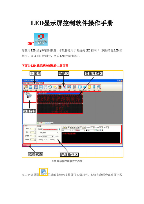
下面为LED显示屏控制软件主界面图LED显示屏控制软件主界面双击光盘里面图标的安装包文件即可安装软件,安装完成后会在桌面出现图标,双击图标,即可进入LED显示屏控制软件的主界面。
☞下面是软件详细的操作说明控制卡查找和显示屏设置控制卡连接好显示屏和电脑后点击工具栏里面的查找屏查找屏使用串口卡或者网口卡连接会在红色字体区域自动显示控制卡的型号和版本号▲(注:使用U盘控制卡可以忽略查找屏步骤,直接设置屏参,编辑好节目点击发送即可)①点击屏参设置按钮设置屏参②输入密码168输入密码③设置好屏参后点击设置屏参按钮屏参设置▲(注:设置屏参里面有一些常用的单元板参数供参考选择)☞下面是一些常见的LED单元板的参数设置推荐1,如果是户外P10的屏,接口是12接口的:(单色)屏参为:数据极性:低,OE极性:高扫描方式: 1/4 扫描,默认4.1扫描方式2,如果是户外P16的屏,接口是12接口的:屏参为:数据极性:低,OE极性:高扫描方式: 1/4 扫描中的4.3扫描方式3,如果是户内φ3.75,φ5 的屏,接口是08接口的:屏参为:数据极性:低,OE极性:低扫描方式: 1/16 扫描4,如果是车载屏P7.62的屏,接口是08接口的:屏参为:数据极性:低,OE极性:低扫描方式: 1/8 扫描▲(注:以上推荐参数都是市面LED单元板的常见参数设置,不排除特殊规格的LED单元板,请以实际情况为准)编辑节目和节目类型介绍①设置好屏参后首先点击工具栏里面的节目按钮即可进入节目编辑节目②点击节目编号可以设置节目播放时段和次数③在工具栏选择不同的节目类型可以进一步详细编辑节目内容1.字幕型节目,在超文本RTF型文件节目中,RTF超文本可对每个字符设置字体、大小,不同的颜色,并可以单独保持该节目的超文本文件,以便以后恢复使用。
LED播放软件说明书

实用文档多媒体显示屏播放系统使用说明书实用文档目录第一章概述 (1)一、前言 (1)二、功能说明 (1)三、系统要求 (3)四、软件安装 (3)五、系统界面 (4)第二章系统功能说明 (8)一、功能按钮说明 (8)二、系统参数配置 (11)三、用户权限管理 (12)第三章排版操作 (14)一、页面功能介绍 (14)二、属性功能介绍 (16)三、调用功能介绍 (19)四、应用功能 (34)五、播放功能 (35)六、通告管理 (36)七、日志管理功能 (37)八、页面定时功能 (37)九、页面模板功能 (38)第四章播放机 (39)一、播放机 (39)第五章显示屏功能 (41)一、显示屏测试功能 (41)第六章网络控制 (42)一、网络控制机 (42)二、网络参数设置 (45)三、网络接收机 (50)第七章系统信息 (51)一、系统信息 (51)二、常见问题 (51)第一章概述一、前言多媒体显示屏播放系统是专门为“播放用途”而设计的,适用于LED大屏幕电子显示屏行业,及播放行业,如电视墙,大屏幕等离子,液晶电视,投影机,展览交易会等等公共场所,广播广告。
只要是在公共场合,需要最方便地,在大屏幕显示屏、电脑显示屏等等媒介上,显示出公共信息、广告、通告之类的信息,都使用到本软件,比如飞机场、火车站、汽车站、证券、广场、购物中心、体育馆、媒体、广告、博览会等等公共场所。
本软件是专门为操作计算机外行者而设计考虑的,它真正能够实现“简单美观的排版编辑,方便快捷的操作使用,全自动化的定时播放,远程操作的网络控制”。
二、功能说明1、直接方便排版,输入、设置字体、颜色、大小、显示动画方式、播放时间等等参数。
可以方便的播放几乎所有的多媒体、动画、图画、文本等格式文件。
◇简单文本;◇图文;字体◇图画格式文件:BMP、ICO、JPG、JPEG、JPE、GIF、CUR、TIF、WMF、EMF等;◇文本格式文件:TXT;◇WORD格式文件:DOC、RTF等;◇EXCEL格式文件:XLS、XLA、XLM、XLT等;◇动画格式文件:VCD/DVD、RM、RMVB、DAT、VOB、AVI、RMVB、RM、MPG、MPEG、GIF、WMV、WMP、WMA、ASF、ASX、RPM、RA、RT、RP、SMI、SMIL、MOV、QT、MP4等;◇FLASH格式文件:SWF文件,FLASH时钟。
- 1、下载文档前请自行甄别文档内容的完整性,平台不提供额外的编辑、内容补充、找答案等附加服务。
- 2、"仅部分预览"的文档,不可在线预览部分如存在完整性等问题,可反馈申请退款(可完整预览的文档不适用该条件!)。
- 3、如文档侵犯您的权益,请联系客服反馈,我们会尽快为您处理(人工客服工作时间:9:00-18:30)。
1 系统概述..........................................................................................................................................1
2 软件安装..........................................................................................................................................2
限 有 技 科 子 电 瓦 诺 T LED 配置工具 多媒体播放器用户指南
目录
目录
目录..................................................................................................................................................... ii
5.3.5 程序加载................................................................................................................................................. 29
5.1.1 使用系统配置文件点亮显示屏 .................................................................................................................. 6
技 5.1.2 通过手动配置点亮显示屏 ......................................................................................................................... 7
西 5.6 显示屏效果调节 ......................................................................................................................................... 33
5.7.3 双校正系数 ............................................................................................................................................. 52
5.7 校正 ........................................................................................................................................................... 34 5.7.1 联机校正................................................................................................................................................. 34
诺 5.3.3 监控资料................................................................................................................................................. 29
5.8 画面控制 .................................................................................................................................................... 53 5.9 监控硬件状态 ............................................................................................................................................. 53 5.9.1 设置刷新周期 ......................................................................................................................................... 54
科 5.1.5 参数固化................................................................................................................................................. 23
5.5 高级颜色配置 ............................................................................................................................................. 31
5.7.2 系数管理................................................................................................................................................. 35
5.1.6 配置文件保存和加载............................................................................................................................... 24
子 5.2 亮度调节 .................................................................................................................................................... 25 电 5.3 多功能卡管理 ............................................................................................................................................. 26 瓦 5.3.1 多功能卡的配置 ...................................................................................................................................... 27
5.3.4 外设管理................................................................................................................................................. 29
司 3 终端连接..........................................................................................................................................3 公 4 功能总览..........................................................................................................................................4 限 5 主要功能介绍.................................................................................................................................. 6 有 5.1 显示屏配置................................................................................................................................................... 6
5.7.4 系数管理................................................................................................................................................. 53
5.1.4 性能参数的调整 ...................................................................................................................................... 17