SIMOTION Measuring Input使用入门
Siemens SIMOTION D435-2 可编程运动控制器数据表说明书

24 V 15 … 30 V -3 … +5 V No 9 mA
subject to modifications © Copyright Siemens AG 2014
6AU1435-2AD00-0AA0
Page 1
Product data sheet
6AU1435-2AD00-0AA0
SIMOTION DRIVE-BASED CONTROL UNIT D435-2 DP/PN; PROGRAMMABLE MOTION CONTROLLER; STANDARD PERFORMANCE; INTERFACES: 12 DI, 16 DI/DO, 6 DRIVE-CLIQ, 2 PROFIBUS, 3 PROFINET PORTS, 2 ETHERNET, 2 USB, 1 OPTION SLOT; INCL. DUAL FAN / BATTERY MODULE AND BATTERY
last change:
Mar 3, 2014
Page 5
Date: 08/07/2014
subject to modifications © Copyright Siemens AG 2014
If used as an input DC input voltage
• rated value • for signal "1" • for signal "0" Electrical isolation Current consumption for "1" signal level, typ.
simulink学习操作方式
Sources库Band-Limited White Noise 把一个白噪声引入到连续系统中Chirp Signal 产生频率增加的正弦信号Clock 显示或者提供仿真时间Constant 产生一个常数值Digital Clock 按指定的间隔产生采样时间Digital Pulse Generator 产生具有固定间隔的脉冲From File 从一个文件读取数据From Work space 从在工作空间定义的矩阵读入数据Pulse Generator 产生固定间隔的脉冲Ramp 产生一个以常数斜率增加或者减小的信号Random Number 产生正态分布的随机数Repeating Sequence 产生一个可重复的任意信号Signal Generator 产生多种多样的信号Sine Wave 产生正弦波Step 产生一个单步函数Uniform Random Number 产生均匀分布的随机数Sinks库Display 显示其输入信号的值Scope 显示在仿真过程产生的信号的波形Stop Simulation 当它的输入信号非零时,就结束仿真To File 写数据到文件To Workspace 把数据写进工作空间里定义的矩阵变量XY Graph 用一个MATLAB图形窗口来显示信号的X-Y坐标的图形Discrete Filter 实现IIR和FIR滤波器Discrete State-Space 实现一个离散状态空间系统Discrete-Time Integrator 离散时间积分器Discrete Transfer Fcn 实现一个离散传递函数Discrete Zero-Pol 实现一个用零极点来说明的离散传递函数First-Order Hold 实现一个一阶保持采样-保持系统Unit Delay 将信号延时一个单位采样时间Zero-Order Hold 实现具有一个采样周期的零阶保持Continuous库Derivative 输出输入信号的微分Integrator 积分一个信号Memory 输出来自前一个时间步的模块输入State-Space 实现现行状态空间系统Transfer Fcn 实现现行传递系统Transport Delay 将输入延迟一给定的时间Variable Transport Delay 将输入延迟一可变的时间Zero-Pole 实现一个用零极点标明的传递函数Nonlinear库Abs 输出输入信号的绝对值Algebraic Constraint 将输入信号约束为零Combinatorial Logic 实现一个真值表Complex to Magnitude-Angle 输出一个复数输入信号的相角和模长Complex to Real-Imag 输出一个复数输入信号的实部和虚部Derivative 输出输入信号的时间微分Dot Product 进行点积Gain 将模块的输入信号乘上一个增益Logical Operator 在输入信号实施一个逻辑操作Magnitude-Angle to Complex 从模长和角度的输入输出一个复数信号Math Function 实现一个数学函数Matrix Gain 将输入乘上一个矩阵MinMax 输出输入信号的最小和最大值Product 输出模块的乘积或者是商Real-Imag to Complex 将输入信号作为是实部和虚部来乘复数信号输出Relational Operator 在输入上进行指定的关系运算Rounding Function 实现一个舍入函数Sign 显示输入信号的符号Slider Gain 按一条斜线来改变标量增益Sum 产生输入信号的和Trigonometric Function 实现一个三角函数Math库Fcn 将一个指定的表达式到输入信号Look-Up Table 实现输入的线性峰值匹配Look-Up Table (2-D) 实现两个信号的线性峰值匹配MATLAB Fcn 应用一个MATLAB函数或表达式到输入S-Function 访问S函数Function &Table库Backlash 对一个具有演示特性的系统进行建模Coulomb & Viscous Friction 刻画在零点的不连续性Dead Zone 提供一个零输出的区域Manual Switch 在两个信号间切换Quantizer 按指定的间隔离散化输入信号Rate Limiter 限制信号的改变速率Relay 在两个常数间切换输出Saturation 限制信号的持续时间Switch 在两个信号间切换Signal &Systems库Bus Selector 有选择的输出输入信号Configurable Subsystem 代表任何一个从指定的库中选择的模块Data Store Memory 定义一个共享的数据存储空间Data Store Read 从共享数据存储空间读数据Data Store Write 写数据到共享数据存储空间Data Type Conversion 将一个信号转换为另外一个数据类型Demux 将一个向量信号分解输出Enable 增加一个使能端到子系统中From 从一个Goto模块接收输入信号Goto 传递模块输入到From模块Goto Tag Visibility 定义一个Goto模块标记的可视视域Ground 将一个未连接的输入端接地Hit Crossing 检测过零点IC 设置一个信号的初始值Inport 为一个子系统建立一个输入端口或者建立一个外部输入端口Merge 将几个输入线合并为一个标量线Model Info 显示、修订控制模型信息Mux 将几个输入信号联合为一个向量信号Outport 为子系统建立一个输出端口,或者是建立一个外部输出端口Probe 输出输入信号的宽度、采样时间并且/或者信号类型Subsystem 表示在另一个系统之内的子系统Terminator 结束一个未连接的输出端口Trigger 增加一个出发端口到子系统Width 输出输入向量的宽度示波器:set(0,'ShowHiddenHandles','on');set(gcf,'menubar','figure');。
SIMOCRANE 集成 STS,GSU 版本 V3.0 软件安装与使用指南说明书

SIMOCRANE integrated STS, GSU Version V3.0These notes take precedence over information in other documents.Please read the notes through carefully because they contain information that it is important for you to know during installation and use of the software.In this version V3.0, the following new features, feature enhancements and feature improvements have been madeSway control functions−New function …Soft Approach“ with consideration of fixed and variable blocked regions in Manual Mode (MAN)−Improving of the function to calculate interpolation points and extending of criterions to start Semi-Automatic Mode (SAM)−Extension of the functional scope of the control bit “START_2D_CALC“−Separated damping factors for acceleration and deceleration (P85, P86, P88, P89)−New parameter (P87) to eliminate the overshooting in positioning process (POS und SAM)−New parameter (P119) for selecting of the lowering point for SAM travel from WS to LS−New parameter (P112, P113) to adapt the trajectory during inclined movement in SAM−Improving of the following error monitoring (E41, E42) for positioning process (POS und SAM) −Expansion of the interface to the higher-level controller (PLC)−New DCC-block “DCC_SCIntPo” to transfer the interpolation points of trajectory to the higher- level controller (PLC)−All camera data will be transferred to the higher-level controller (PLC)−General troubleshooting−Adaption of parameters (Limit values, default value or option)−Extending and improvement of the operation instructions manualsCommissioning and Diagnostic Tool …CeCOMM”−Extending of visualization (limit lines, safety clearance, immersion point…)−Adding the time stamp to the long-time trace−Increasing the number of logger files to 12−New function to calculate the maximum sway deflection−Improvement of the diagram in X/Y-view−Improving of the trace function−Adding a list of all variable signals for trace−TroubleshootingThe Version V3.0 is downwards compatible to the version V 2.1 SP2 HF1. Due to the functional and interface extension, adjustments and new commissioning are required for upgrading. More information about the V2.1 SP2 HF1 refers to the product update for its delivery release:https:///cs/ww/en/view/109750239Contents1. SCOPE OF SUPPLY1.1 DVD1.2 Certificate of License2. NOTES ON INSTALLATION2.1. System requirements2.1.1 Hardware2.1.2 Optional Hardware2.1.3 Software2.2. Installation2.3 Unstalling3. CONSTRAINTS AND FUNCTIONAL RESTRICTIONS1 Scope of Supply1.1 DVDThe DVD contains:The version V3.0 is downwards compatible to the V2.1 SP2 HF1. The software will be put in production and additionally provided for download in internet under ‘Industry Online Support international with Download-ID 109220170, see the following link:https:///cs/ww/en/view/103965095Users can upgrade their application if required. Please pay attention to the preconditions in the operation manual, 07/2019. More information to upgrade your application refer to the FAQhttps:///cs/ww/en/view/109478006Limitation of liabilityThe Software package includes following application examples:•Application example for STS•Application example for GSUThe application example inside the software package are provided free of charge. The customer is granted the non-exclusive, non-transferable, free right to use it. This includes the right to modify the application example, to reproduce it modified or unmodified, and to combine it with the user's own software.All liability, on whatever legal basis, in particular based on errors in the software or the associated documentation or damage resulting from advice, is excluded unless liability is mandatory, for example, due to malice, gross negligence, injury to life, body, or health, due to acceptance of a quality warranty, due to fraudulent concealment of a defect, or due to breach of substantial contractual obligations. This does not imply a reversal of the burden of proof to the detriment of the customer.The customer is furthermore obligated to release SIEMENS AG from any claims of third parties where such claims arise in connection with use of the software by the customer.German law shall apply. The courts of Erlangen shall have exclusive jurisdiction.Safety instructionsSiemens provides products and solutions with industrial security functions that support the secure operation of plants, solutions, machines, equipment and/or networks. They are important components of a holistic industrial security concept. The products and solutions from Siemens are continuously developed with this aspect in mind. Siemens recommends strongly that you regularly check for product updates.For the secure operation of Siemens products and solutions, it is necessary to take suitable preventive action (e.g. cell protection concept) and integrate each component into a holistic, state-of-the-art industrial security concept. Any third-party products that may be in use must also be taken into account. You will find more information about industrial security at: /industrialsecurityConstantly up-to-date information on SIMOCRANE products, product support, FAQs can be found on the Internet: https:///cs/ww/en/ps/200871.2 Certificate of LicenseIn the licensing method used for SIMOTION dependent on the way and number of the runtime components used in the project different licenses must be acquired. The licenses required for a device are assigned to a License key. The license is bound about the serial number of the CF card.The compact flash card (CF card) is not in the scope of supply; a license key must be generated and transferred to the CF card. This will be realized with the help of the enclosed "Certificate of License".Further indications for the license handling will be available in the operating instructions. "SIMOCRANE SC integrated STS, GSU”2 Notes on Installation2.1. System requirementsThe preconditions are a main crane controller system with a PROFIBUS/PROFINET interface as well as continuously controllable drives.Depending on the task to be performed and the environmental conditions, the sway control system can be used with or without a SIMOCRANE CenSOR V2.0 HF3 camera measuring system.The hardware and software required for the camera measuring system must be ordered separately and are not listed here.A version with the necessary hardware components and the required license authority must be available.2.1.1 Hardware• SIMOTION D435-2 DP/PN as of firmware V5.2 SP1 or higher•SINAMICS, as of firmware V5.1.HF1 or higher2.1.2 Optional hardware•SIMOCRANE CenSOR V2.0 HF3•Reflector2.1.3 Software• SIMOTION SCOUT as of Version V5.2 SP1•Optional package Drive Control Chart (DCC) for SIMOTION / SINAMICS as of version V3.1 SP1 •SIMOCRANE Basic Technology Version V3.0•Commissioning and diagnose tool SIMOCRANE CeCOMM ab Version V4.4.2.4•SIMOCRANE SC integrated STS, GSU V3.0•Microsoft Windows 7 or 10•SIMATIC Manager ab V5.62.2. InstallationThe software package contains a setup file. You can use it to install the DCC library "SwayControl." The precondition is that the SIMOTION SCOUT software has been installed and the user is logged onto the PC with administrator rights."Setup_CeCOMM.exe"The installation program leads you step by step through the whole installation process. Installation isperformed as follows:•The SIMATIC Manager and the SCOUT must be closed before the setup is run.•For the procedure for linking the "Sway Control DCC Library" into your SIMOTION user project, see the operating instructions "SIMOCRANE_SC_integrated_STS_GSU_de.pdf" Chapter 5.The software package contains a setup file for the "SIMOCRANE CeCOMM" diagnostics and commissioning tool. The program can run under the WINDOWS 7 or WINDOWS 10 operating system. This requires that the user is logged in the PC with administration rights.Setup_CeCOMM.exeThe installation program guides you through the entire installation process step by step. After installation the diagnostic program will be available under "Windows Start → Programs."2.3UninstallingVia Windows Start →Control panel →Programs, you can uninstall the diagnostics tool installed via setup.3. Constraints and functional restrictionsMethod of operation P140 (3525253)P140 must be left as 0.Function of the P77 (3534325)Leave the parameter P77 with its default value (200).Function of the parameters P149 and P150 (3555469)Leave the parameters P149 and P150 with their default values (0).Function of the P111 (752485)An Adjustment of 0 or 1 for P111 causes no smoothing. Between these values decreasingvalues lead to an increasing smoothing. Values smaller than 0,1 should be avoided. Thesmoothing has no influence to the closed-loop control and effects only the display of the trace in CeCOMM.Workaround: Leave the parameter P111 with its default value (0).P53 Acceleration reduction when hoisting (751425)With values of the parameter P53 < 100 %, unexpected acceleration behaviour of the hoist may occur.Workaround: Parameter P53 must be left with its default value (100%).Warning messages E20 to E27 (1002665)Warning messages E20 to E27 do not work. Functioning of the prelimit switch and limit switchmust be assured in the higher-level control.Target control function (301654)In the case of the hoist and trolley, the target control function results in the target always beingtraveled to with a deviation from P162 or P165 (positioning accuracy). Parameters P163 andP160 must not be less than 0 if the target is to be traveled to without this deviation.Workaround: Do not set parameters P163 and 160 smaller than 0.Stopping a cylinder movement in operation mode “Cylinder jogging”As a result of incorrect Position sensing it may happen that despite correct control according to the operation instructions the movement of the Cylinder cannot be stopped.Workaround: By resetting of the control bit …move“ the cylinders can be stopped ev en in case of incorrect positon sensing (without down ramp).The time-optimal control algorithmus is not used for STS-cranes.Workaround: The time-optimal control algorithmus (P152) should not be used for STS-cranes(P102=1).Operation mode …Cylinder jogging“As a result of incorrect Position measurement it may happen thatDespite correct control according to the operation instructions the movement of the Cylindercannot be stopped.Despite of the selection of only one cylinder more cylinders are moving at the same time.Workaround:By resetting of the control bit …move“ the cylinders can be stopped even in case of incorrectpositon sensing (without down ramp).With an interlock (in PLC) of the state bits …a_out“ up to …d_out“ and …a_in“ up to …d_in“(Zyl inder retract and extend) with the corresponding control bit …a_in_comm“ up to…d_in_comm“ and …a_out_comm“ up to …d_out_comm“ it is possible that only the selectedcylinder is moving.Trolley uncontrolled acceleration (4310214)Trolley uncontrolled acceleration.Abhilfe:Use the delivered new application project.End。
SIMOTIONCAM功能使用入门
SIMOTION CAM功能使用入门 SIMOTION CAM FUNCTION Getting Start摘要 本文介绍SIMOTION CAM功能的使用及编程。
关键词SIMOTION CAM功能Key Words SIMOTION CAMA&D Service & Support Page 2-23目录_Toc2088215861.SIMOTION CAM功能介绍 (4)2.配置主轴和从轴 (4)2.1 建立驱动设备 (4)2.2 轴的插入 (6)2.3 主轴与从轴的耦合 (8)2.4主轴与从轴的同步的设定 (8)2.5 设定CAM曲线 (12)2.5.1 通过插补表设定CAM曲线 (14)2.5.2 通过多项式生成CAM曲线 (16)2.5.3 将CAM曲线与主轴从轴连接 (18)3.编写CAM程序 (18)3.1 轴使能及回零点 (18)3.2使能及解除CAM1 (19)3.3使能及解除CAM2 (20)3.4故障处理程序 (20)3.4.1 工艺对象故障处理程序 (20)3.4.2 外设故障处理程序 (20)3.5程序执行系统的分配 (20)3.6运行CAM时运动轨迹跟踪 (21)3.6.1 CAM1运动轨迹跟踪 (21)3.6.2 CAM2运动轨迹跟踪 (22)3.7示例程序 (22)A&D Service & Support Page 3-231.SIMOTION CAM功能介绍在运动控制应用中,经常需要多个轴的同步控制,例如设定一个轴为主轴,其它的轴为从轴,从轴跟随主轴的运动而作响应的运动,主轴可以是一个实轴也可以是一个虚轴或是一个外接的编码器。
在实际应用中主轴的速度和位置值是一个测量值,容易受到测量周期及外部环境的影响而产生扰动,这样在从轴上产生更大的扰动,这种情况下可以采样虚轴作为主轴,将主轴的值经过优化计算后再传递给从轴,从而从轴减少速度和位置的扰动。
SIMetrixSIMPLIS使用说明
SIMetrix/SIMPLIS 使用说明
1. 如何选择仿真器 ......................................................................................................2 2. 原理图绘制 ..............................................................................................................4
Logic Elements:包含各类常用可编辑数字逻辑元件、触发器等 9 Place| Connectors:母线连接、端口命名、地 9 Place| Probe:查看波形的探头。可查看端点电压、端点电流、导线内电流、电
压差等。 9 Place| Magnetics:包含理想与非理想电感,变压器模型。 9 Place| Voltage Sources:电压源、波形发生器以及专用与 AC 分析的 AC 源 9 Place| Current Sources:电流源、波形发生器以及专用与 AC 分析的 AC 源 9 Place| Control Sources:四类受控源 9 Place| Semiconductors:二极管、晶体管、MOSFET、JFET
9 Place| From Model Library:目前安装在软件中的模型库。用户可以从中获取二 极管、运放、MOSFET 芯片等元件。如下图所示:
9 Place| From Building Block Library:BB library 是专用于 SIMPLIS 建模的一个 库,也可以用来绘制原理图。它包含三个部分:
simotion_基本使用手册
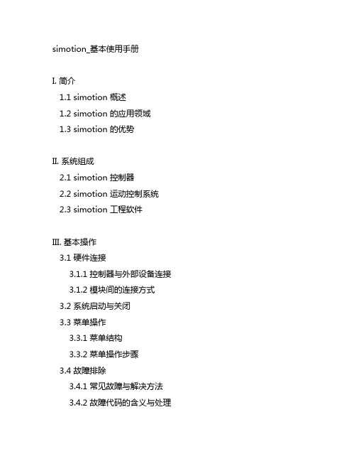
simotion_基本使用手册I. 简介1.1 simotion 概述1.2 simotion 的应用领域1.3 simotion 的优势II. 系统组成2.1 simotion 控制器2.2 simotion 运动控制系统2.3 simotion 工程软件III. 基本操作3.1 硬件连接3.1.1 控制器与外部设备连接 3.1.2 模块间的连接方式3.2 系统启动与关闭3.3 菜单操作3.3.1 菜单结构3.3.2 菜单操作步骤3.4 故障排除3.4.1 常见故障与解决方法 3.4.2 故障代码的含义与处理IV. 编程基础4.1 编程环境介绍4.2 编程语言及其特点4.3 编程实例演练4.3.1 简单的运动控制程序编写 4.3.2 系统故障处理的程序编写 4.4 调试与测试4.4.1 程序调试的基本方法4.4.2 程序测试的注意事项V. 运动控制5.1 运动控制原理5.2 运动控制参数设定5.3 运动控制程序设计5.3.1 位置控制程序设计5.3.2 速度控制程序设计5.4 运动学习与优化5.4.1 运动学习的方法5.4.2 运动优化的技巧VI. 系统维护6.1 系统备份与恢复6.1.1 控制器程序的备份方法6.1.2 系统参数的备份与恢复6.2 系统更新与升级6.3 系统性能监控6.3.1 系统各部分性能指标6.3.2 性能监控方法及工具VII. 故障处理7.1 硬件故障处理7.1.1 控制器故障处理7.1.2 模块故障处理7.2 软件故障处理7.2.1 程序故障处理7.2.2 系统故障处理VIII. 安全操作8.1 安全操作规程8.1.1 机器设备安全操作规程8.1.2 simotion 控制系统安全操作规程 8.2 应急处理8.2.1 突发情况的处理步骤8.2.2 安全设备的使用与保养IX. 使用注意事项9.1 温度与湿度要求9.2 电源要求9.3 使用环境要求9.4 维护保养要点结语simotion 控制系统的使用教程至此结束。
SIMOTION 编程指南介绍
规则 22: 主体控制结构中的每个指令均被缩进,须整齐。
规则 23: 如果功能或功能块提供错误代码,这些错误码必须始终应始终声明。
Example: FUNCTION FCSwapWord : WORD //description
推荐:尽可能的避免在程序中访问操作 SIMOTION 设备的过程映像,以提高代码 的可移植性。应在集中的位置进行 IO 的定义。
Example: //declaration boJogPos AT %IX10.1 : BOOL; b8Port1 AT %IB1 : BYTE; i16ToolKey AT %IW10 : INT; //cast possible i32ProgNum AT %QD10 : DINT; //access to I/O-Image
Example: i8SetValue := i8SetValue1 + i8SetValue2; //ok i8SetValue:=i8SetValue1+i8SetValue2; //not ok
推荐:表达式应始终设置在方括号中,以清楚显示的顺序解释。
Example: boSetFlag := (r32ActualPosition < 100.0) OR (r32ActualPosition > 150.0);
SIMOTION 编程(一) 2013-05-16
在SCOUT光盘里,有个非常详细的编程指南(点击此处查看),非常好,只是不 知道为什么被放在这么不起眼的位置。该编程指南用来帮助用户获得一个标准、 统一的代码,并且使代码可以更容易地维护和重新使用。不仅如此,错误可以在 早期阶段(例如,由编译器)被识别和避免。
SIMOTION D系统组态及调试入门
而作为控制系统的工程工具,SCOUT 除了能实现以上功能外,还能进行以下工作: • 轴控制参数的设定 包括轴的机械参数、回零点方式及运动性能参数的设定。 • 控制程序编辑 包括运动控制、逻辑控制以及工艺控制。运动控制任务的图形化编程运动控制图 (MCC) 可以以流程图的方式对机器程序顺序进行图形化编程。程序也可以用LAD及FBD编程。 对于复杂的逻辑控制、数学运算及运动控制还可以用ST结构化编程语言进行编程。这 三种编程方式均集成在SIMOTION SCOUT软件中。
SIMOTION 特别关注其 SCOUT 工程开发系统的用户友好性。 运动控制、逻辑控制与工艺控制 的工程开发,以及驱动器的组态与调试,均是由一个系统完成的。 实际上所有任务的处理均 可用图形方式完成,包括组态、编程、测试及调试。 友好的用户提示信息,实用的帮助功 能,自动的检查功能简化了任务的完成过程,特别适合于第一次编制运动控制程序的用户。 SCOUT 的所有工具均被集成在一起,并具有统一的形式。
SIMOTION D 系统组态及调试入门
SIMOTION D System Configuration And Commissioning Getting Start
快速入门
Edition 03/ 2007
摘要 本文介绍了 SIMOTION D 运动控制系统项目的建立、系统调试及运动控制程序的编写。 关键词 SIMOTION D 运动控制系统、项目建立、调试、编程 Key words SIMOTION D Motion Control System、Create Project、Program
- 1、下载文档前请自行甄别文档内容的完整性,平台不提供额外的编辑、内容补充、找答案等附加服务。
- 2、"仅部分预览"的文档,不可在线预览部分如存在完整性等问题,可反馈申请退款(可完整预览的文档不适用该条件!)。
- 3、如文档侵犯您的权益,请联系客服反馈,我们会尽快为您处理(人工客服工作时间:9:00-18:30)。
SIMOTION Measuring Input function Introduction
Getting-started
Edition (2010 年-2 月)
摘 要 本文介绍了 SIMOTION Measuring Input 功能的使用方法和相关信息 关键词 SIMOTION, Measuring Input Key Words SIMOTION, Measuring Input
IA&DT Service & Support
Page 5-20
z Listening Measuring Input TO 不能进行激活或取消激活,而是取决于其 Original Measuring Input TO。
z Listening Measuring Input TO 不能选择边沿触发方式以及测量范围,而是由其 Original Measuring Input TO 来决定
z Listening Measuring Input TO 要正确设置处理周期(process cycle) 和系统号 (system number), 处理周期可以和 Original Measuring Input TO 不同,但会影响 精度, 系统号为 Listening Measuring Input TO 连接轴的编码器编号。
上升和下降沿
第一个上升沿发生时的值
第一个下降沿发生时的值
表 1 触发信号不同时的测量值对比 注:TM15 能支持 Global Measuring Input,但不能支持 Cyclic Measuring Input
1.4 时间戳功能 (仅限于 Global Measuring Input) 对于 Global Measuring Input,每次测量时的当前时刻(时间戳)都会被保存下来,这样位 置值就会精确地被记录,而不会由于系统处理的时间延迟导致位置偏差,但只有特定的硬件 才能支持时间戳功能。支持的硬件和支持 Global Measuring Input 的硬件相同,见表 2。
IA&DT Service & Support
Page 3-20
1. 概述
Measuring Input TO 用于快速,准确地记录某一时刻轴或编码器的位置值。根据支持硬件及 功能的不同,Measuring Input 功能可分为 Local Measuring Input 和 Global Measuring Input。Local Measuring Input 用于对单个轴或编码器的位置值进行记录,其测量点是固定 的,通常是通过集成在驱动中的测量点来完成,在系统配置时通过 Measuring Input Number 来确定相应的测量点。Global Measuring Input 可对单个或多个轴或编码器的位置值进行记 录,并且带有时间戳功能,可更精确地记录位置信息。它对应的测量点通过设置硬件地址来 确定。Measuring Input 相关的基本概念如下:
IA&DT Service & Support
Page 2-20
目录
1. 概述 .................................................................................................................................. 4 1.1 测量范围Measuring Range ..................................................................................... 4 1.2 触发方式的选择 ....................................................................................................... 4 1.3 单次测量与循环测量................................................................................................ 4 1.4 时间戳功能 (仅限于Global Measuring Input) ........................................................... 5 1.5 Listening Measuring Input (仅限于Global Measuring Input) .................................... 5 1.6 Measuring Input TO的分配和连接 ........................................................................... 6 1.7 支持Measuring Input功能的相关硬件 ...................................................................... 7 1.8 Measuring Input的监控............................................................................................ 7 1.9 Measuring Input仿真 ............................................................................................... 8
1.1 测量范围 Measuring Range Measuring Input 可设置一定的测量范围,可使 Measuring Input 功能只在该段位置范围内才 激活。如果设定的起始值大于结束值,对非模态轴,系统会将两个值对调,对于模态轴,则 直接延伸至下一周期。
1.2 触发方式的选择 对于单次测量(见节 1.3),有如下的触发方式选择:
IA&DT Service & Support
Page 4-20
z 单次测量(One-time measurement):使用命令“_enableMeasuringInput”激活,只执 行一次,完成后自动停止,下次测量需重新激活。单次测量也可通过指令停止。
z 循环测量(Cyclic measurement)(仅 Global Measuring Input 支持循环测量):使 用命令“_enableMeasuringInputCyclic”激活。循环测量会一直执行直到用指令去停 止。
1.5 Listening Measuring Input (仅限于 Global Measuring Input) 通过使能Listening measuring Input功能可以使一个测量点同时记录多个轴或编码器的位置。 通过组态可以设置Listening measuring Input功能。 Listening measuring Input 功需要使用时间戳的功能,因而只能是支持 Global Measuring Input TO 的硬件才能使用,在使用时要注意:
根据所设定的触发方式的不同,最终测到的位置值也不同,如下表:
测量方式 单次测量 循环测量
触发信号设定
measuredValue1
measuredValue2
第一个上升沿或下降沿(两者选 仅上升沿或仅下降沿 一,取决于触发信号的设定)时的 无值
位置值
上升和下降沿
第一个沿信号(无论是上升沿还是 第二个沿信号(无论是上升沿
z 一个 Measuring Input TO 可以连接多个的 Listening Measuring Input TO z 一个轴/编码器可以同时连接多个 Measuring Input TO 和 Listening Measuring Input
TO,或两者混合使用。 z Original Measuring Input TO 只有输出没有输入接口,Listening Measuring Input
下降沿均可)发生时的值
还是下降沿均可)发生时的值
上升和下降沿以上升 沿开始
第一个上升沿时的位置值
上升和下降沿以下降 沿开始
第一个下降沿时的位置值
第一个下降沿时的位置值 第一个上升沿时的位置值
仅上升沿或仅下降沿
第一个上升沿或下降沿(两者选 一,取决于触发信号的设定)时的 位置值
发生在同一个处理周期中的第 二个上升沿或下降沿(两者选Байду номын сангаас一,取决于触发信号的设定) 时的位置值
z 仅上升沿 z 仅下降沿 z 上升沿或下降沿 z 上升沿或下降沿,但是以上升沿开始 z 上升沿或下降沿,但是以下降沿开始 对于循环测量(见节1.3),有如下的触发方式选择: z 仅上升沿 z 仅下降沿 z 上升沿或下降沿
1.3 单次测量与循环测量 Measuring Input 功能根据测量次数的不同分为两种:
2. Measuring Input基本配置过程........................................................................................... 8 2.1 Global Measuring Input的配置 ................................................................................ 8 2.1.1 SIMOTION D4xx 的Global Measuring Input配置.............................................. 8 2.1.2 TM15/TM17 的Global Measuring Input配置 ................................................... 10 2.1.3 C240 (B1-B4) 的Global Measuring Input配置................................................. 11 2.2 Listening Measuring Input 配置 ............................................................................. 12 2.3 Local Measuring Input配置.................................................................................... 12