广泰数控gtc2E说明书
E21 数控操作手册说明书

E21Operation Manual(Version:V1.07)Contents Preface (1)Chapter1Product Overview (2)1.1Product introduction (2)1.2Operation panel (2)1.3Displayer (4)Chapter2Operation Instruction (5)2.1Basic operation procedure (5)2.2Programming (6)2.2.1Single-step programming (6)2.2.2Multi-step programming (8)2.3Parameter setting (12)2.4Manual adjustment (14)Chapter3Alarm (16)Appendix Common fault and troubleshooting (18)PrefaceThis manual describes operation of E21numerical control device and is meant for operators who are instructed for operation of the device.Operator shall read through this manual and know operation requirements before using this device.Copy right is preserved by ESTUN.It is not allowed to add or delete part or all of the manual content without ESTUN’s consent.Do not use part or all of manual content for the third party’s design.E21device provides complete software control and has no mechanical protection device for operator or the tool machine.Therefore,in case of malfunction,machine tool must provide protection device for operator and external part of the machine tool.ESTUN is not responsible for any direct or indirect losses caused by normal or abnormal operation of the device.ESTUN preserves the right to modifying this manual in the event of function adding or print error.Chapter1Product Overview1.1Product introductionThis product is equipped with press brake machine dedicated numerical control device which is applicable to various users.On the basis of ensuring work precision,the cost of numerical control bending machine is reduced significantly.Features of this product are listed below:●Positioning control of back gauge.●Intelligent positioning control.●Unilateral and bidirectional positioning which eliminates spindle clearance effectively.●Retract functions.●Automatic reference searching.●One-key parameter backup and restore.●Fast position indexing.●40programs storage space,each program has25steps.●Power-off protection.1.2Operation panelOperation panel is shown in Figure1-1.Figure1-1Operation panelFunctions of panel keys are described in Table1-1.Table1-1Description of key functionsKey Function descriptionDelete key:delete all data in input area on left bottom of displayer.Enter key:confirm the input content.If no content is input,the key has the similarfunction to direction key.Start key:automatic start-up,top left corner of the key is operation indicatorLED.When operation is started,this indicator LED is on.Stop key:stop operation,top left corner of the key is Stop indicator LED.Wheninitialize normal start-up and no operation,this indicator LED is on.Left direction key:page forward,cursor removeRight direction key:page backward,cursor removeDown direction key:select parameter downwardFunction switch:switch over different function pagesSymbolic key:user input symbol,or start diagnosis.~Numeric key:when setting parameter,input value.Decimal point key:when set up parameter,input decimal point.Manual movement key:in case of manual adjustment,make adjustment objectmove in forward direction at low speed.Manual movement key:in case of manual adjustment,make adjustment objectmove in backward direction at low speed.High speed selection key:in case of manual adjustment,press this key andpress simultaneously,make adjustment object move in increasingdirection at high speed,then press,make adjustment object move indecreasing direction at high speed.1.3DisplayerE21numerical control device adopts160*160dot matrix LCD displayer.The display area is shown in Figure1-2.Figure1-2Display area●Title bar:display relevant information of current page,such as its name,etc.●Parameter display area:display parameter name,parameter value and systeminformation.●Status bar:display area of input information and prompt message,etc.The paraphrases of shortening on this page are as shown in Table1-2.Table1-2The paraphrases of shorteningShortening DescriptionX The current backgauge positionY The current slider positionXP The desired backgauge positionYP The desired slider positionDX Backgauge retract distanceHT Holding delayDLY Retracting delayPP Preset workpieceCP Current workpieceChapter2Operation Instruction2.1Basic operation procedureBasic switch over and operation procedure of the device is shown in Figure2-1.Figure2-1Basic Operational Flow2.2ProgrammingThe device has two programming methods,which are single-step programming and multi-step er can set up programming according to actual demand.2.2.1Single-step programmingWhen the parameter X or Y displays********on the page,please do notenter the RUN page or Manual page,unless you have reset the teachfunction of X-axis or Y-axis.Single-step programming is generally used for processing single step to finish work piece processing.When controller is power on,it will automatically enter single-step program page. Operation stepsStep1After starting up,the device will enter setting up page of single-step program automatically,as shown in Figure2-2.Figure2-2Single-step program setting pageStep2Press,select parameter which needs to be set up,press numerical key to inputprogram value,press to complete input.[Note]Parameter can only be set when Stop indicator is on.Setting range of singe step parameter is shown in Table2-1.Table2-1Set up range of singe step parameterParameter name Unit Set up range RemarksX mm/inch-Current position of X axis,unable to bemodified.Parameter name Unit Set up range RemarksY mm/inch-Current position of Y axis,unable to bemodified.XP mm/inch0~9999.999Program position of X axis.YP mm/inch0~9999.999Target position of Y axis.DX mm/inch0~9999.999Retract distance of X axis.HT s0~99.99The time between concession signal validand end hold time output.DLY s0~99.99In case of single step,delay time for X axisconcession.PP-0~9999Number of preset work piece.CP-0~9999Number of current work piece.Step3Press,system will execute according to this program,as shown in Figure2-3.Figure2-3Single step operation pageOperation exampleOn single-step program page,program bending depth to100.0mm,back gauge position to 80.00mm,retract distance to50mm,concession waiting time to2s,holding time to3s,work piece to10.Operation steps are shown in Table2-2.Table2-2Operation steps of single step exampleOperation steps OperationStep1Press,select“XP”parameter.Step2Input80.00by numerical key.Step3Press,confirm setting of this parameter.Operation steps OperationStep4Press,select“YP”parameter.Step5Input100.0by numerical key.Step6Press,confirm set up of this parameter.Step9Press,select“DX”parameter,“DLY”parameter,“HT”parameter,“PP”parameter respectively.Step10Set up parameter to50mm,2s,3s,10,0by numerical key.Step11Press,system execute according to this program.2.2.2Multi-step programmingWhen the parameter X or Y displays********on the page,please do notenter the RUN page,unless you have reset the teach function of X-axis orY-axis.Multi-step program is used for processing single work piece of different processing steps, realize consecutive implementation of multi-steps,and improve processing efficiency. Operation stepStep1Power on,the device displays the single-step parameter page automatically.Step2Press,switch to program manage page,as shown in Figure2-4.Figure2-4Program management pageStep3Press,select program serial number,or input program number directly, such as input“1”.Step4Press,enter multi-step program setting page,as shown in Figure2-5.Figure2-5Multi-step program setting pageStep5Press,select multi-step programming parameter which requires set up,inputsetting up value,press,and the set up takes effect.Step6In completion of set up,press,enter step parameter set page,as shown in Figure 2-6.Figure2-6Step parameter set pageStep7Press,select step parameter that needs to be set up,input program value, press,and the setup takes effect.Step8Press to switch over between steps.If the current step is the first step,press to enter the last page of step parameter setting;if the current step is thelast one,press to enter the first page of step parameter setting.Multi-step parameter setting range is shown in Table2-3.Table2-3Multi-step parameter setting rangeParameter name Unit Setting range Remarks Step number of program-0~25Set up total processingstep number of thisprogramParameter name Unit Setting range Remarks Preset work piece number-0~9999Number of work piece tobe processed,decreasing piece whenmore than zero;negativeincreasing count.Current work piece number-0~9999Number of finished workpiece Concession delay s0~99.99Time between retractsignal and concessionexecution.Holding time delay s0~99.99Time betweenconcession signal andend pressurize output X mm/inch-Current position of Xaxis,can’t be modified;Y mm/inch-Current position of Yaxis,can’t be modified;X target position mm/inch0~9999.999Program position of Xaxis;Y target position mm/inch0~9999.999Target position of Y axis;concession distance mm/inch0~9999.999Distance of X axisconcession;Repeat times-1~99Repeat times required bythis step.Step9Press,system will operate according to this program,as shown in Figure2-7.Figure2-7Multi-step programming operation pageOperation example[Background]One work piece requires processing50as shown below;●First bend:50mm;●Second bend:100mm;●Third bend:the other direction300mm;[Analysis]according to work piece and technological conditions of machine tool:●First bend:X axis position is50.0mm;Y axis position is85.00mm,concession50mm;●The second bend:X axis position is100.0mm;Y axis position is85.00mm,concession50mm;●The third bend:X axis position is300.0mm;Y axis position is85.00mm,concession50mm;Edit processing program of this work piece on No.2program.Operation procedure is shown in Table2-4.Table2-4Operation steps of multi-step programming exampleNO.OperationStep1On single step parameter setting page,press to enter programselection page.Step2Input“2”,press,enter multi-step general parameter setting page of program2.Step3Select“Program step”,input“3”,press,the setting takes effect.Step4Select“number of preset work piece”,input“50”,press,the setup takes effect.Step5Similar to step3and step4,set“current work piece number”,“concession delay”and“pressurize time”to0,400,200respectively.Step6Press to enter first step setup page of step parameter.Step7Select“X target position”,input50,press,the setup takes effect.Step8Select“Y target position”,input85,press,and the setup take effect.NO.OperationStep9Similar to step7,8,set up“concession distance”and“repeat times”to50,1 respectively.Step10Press to enter second step setup page of step parameter,the setup method is similar to that of step one.Step11Press again,to enter third step setup page of step parameter,the setup method is similar to that of step one and step two.<Note>■In completion of multi-step programming,return to start stepbefore launching the system;otherwise,the program will startposition processing at current step.■Press left and right direction key to circulate page turning andbrowsing among all step parameters.■Program can be called and revised again.■In completion of processing all work pieces(50in the example),system stops automatically.Restart directly will start another roundof processing50work pieces.2.3Parameter settingUser can setup all parameters required for normal operation of the system,including system parameter,X axis parameter and Y axis parameter.Step1On program management page,press to enter programming constant page,as shown in Figure2-8.On this page,programming constant can be set.Figure2-8Programming constant pageRange of programming constant setup is shown in Table2-5.Table2-5Range of programming constant setupParameter name Unit Range Default Remarksmm/inch-0or100:mm,1:inch中文/English-0or100:Chinese,1:EnglishRelease Time s0to99.990.3Continue time of unloading outputafter starting the system.Pulse Time s0.000to1.0000.200The duration of the pulse signal. Version---Software version information,Vrefers to version.1:indicates version number.0:indicates version level.Step2Input password“1212”,press to enter the Teach Page,as shown in Figure 2-9.Figure2-9System parameter setting pageStep up parameter,parameter setup range is shown in Table2-6.Table2-6System parameter setup rangeParameter Name Unit Range Default RemarksX-tea.in mm0~9999.9910In teach enable,input currentposition of X axisY-tea.in mm0~9999.9910In teach enable,input currentposition of Y axis<How to Teach>:You can directly measure the positions of slider and back gauge.Ifthe measurement is difficult,you can program and operate any oneprocess,and then measure the accomplished workpiece.Step 3Press ,return to programming constant page.----End2.4Manual adjustmentIn single-step mode,axis movement can be controlled by pressing key manually.This method helps user to adjust machine tool and work piece.Step 1On single step parameter setup page,press orto enter manual page,asshown in Figure 2-10.Figure 2-10Manual pageStep 2According to your actual requirement,following the above table to adjust the position of the axis.-If the drive mode of the corresponding axis is common motor :Press KeyStatus Direction Running Time Speed Stop increasing Press timeSlow Run increasing ●Press time (if it is less than “Pulse Time”)●Pulse Time (If it is less than Press time)Slow Stop decreasing Press timeSlow Run decreasing ●Press time (if it is less than “Pulse Time”)●Pulse Time (If it is less than Press time)Slow +Stopincreasing Press time Slow Run increasing Press time Slow +Stopdecreasing Press time Slow RundecreasingPress timeSlow<Note>:When the system is on run status,the operation of manual adjustment is just valid for the X-axis.-If the drive mode of the corresponding axis is frequency :Press Key Status Direction Running Time Speed Stop increasing Press time SlowRun Cannot do itStop decreasing Press time SlowRun Cannot do it+Stop increasing Press time Fast Run Cannot do it+Stop decreasing Press time Fast Run Cannot do itStep3Press return to single step parameter setting page.----EndChapter 3AlarmThe device can detect internal or external abnormity automatically and send out alarm prompt.Alarm message is available on alarm list.Step 1On programming management page,press to enter programming constantpage.Step 2On programming constant page,press to enter “Alarm history”page to view allalarm history.As shown in Figure 3-1,the latest 6alarms,alarm number and causes can be viewed on thispage.Figure 3-1Alarm history pageAlarm history and message is shown in Table 3-1.Table 3-1Alarm number and alarm messageAlarm number Alarm nameAlarm descriptionA.02XPos <minimum Move X-axis forwards in Manual Movement.A.03XPos >maximum Move X-axis backwards in Manual Movement.A.04YPos <minimum Move Y-axis forwards in Manual Movement.A.05YPos >maximum Move Y-axis backwards in Manual Movement.A.06X out of lmt.Re-teach the position of X-axis.A.11Count reached shut-down Rerun,the alarm is cleared automatically.A.12Beam is not on upperdead point Step on the Foot Up Switch,moving the slider to the TDC,and the alarm will be cleared automatically.A.13X Un-teachIn Re-teach the position of X-axis.A.14Y Un-teachInRe-teach the position of Y-axis.Alarm number Alarm name Alarm descriptionA.21Oil pump not startedCheck whether the pump signal is connected,and check whether the pump switch is on. A.22Encoder failure Check whether the encoder wiring is normal.A.25Drive mode err Reprogram the Drive Mode for X-axis and Y-axis.A.26X Stop Err Check whether the back gauge motor is run normally.A.27Y Stop Err Check whether the slider motor is run normally.A.28X V2ErrCheck whether the back gauge motor is runnormally.A.29X V3Err Check whether the back gauge motor is run normally.A.30Y V2Err Check whether the slider motor is run normally.A.31Y V3Err Check whether the slider motor is run normally.A.32XPos<0Move X-axis forwards to the setting range in Manual Movement.A.33YPos<0Move Y-axis forwards to the setting range inManual Movement.A.41Parameter storage error Back to factory for repairing----EndAppendix Common fault and troubleshooting Fault phenomena Trouble shootingThe screen don’t display when power on.●The terminal of power supply wiring is error.Followthe nameplate to rewire.●The source voltage is too low.●The connector is not connected well.The back gauge motor doesn’t run when X-axis is operated,but the slider motor runs.The wires of these two motor are in reverse,please rewire.The motor doesn’t run when operating.●Check whether the machine is impeded,or whetherthe slider is back to TDC●Check whether the motor wire is connected well.The motor can’t mutually convert from high to low ●Check whether the signal is in effect,or whetherfrequency converter is normal.●Check whether parameter Mute Dis.is programmedcorrectly.The step can’t be changed in Multi-Step mode.Check the START terminal is connected to+24V when the slider is on TDC.The counter doesn’t work in Multi-Step mode.Check the START terminal is connected to+24V when the slider is on TDC.Lose control of the system●Check whether the encoder cable is connected well.●Check whether the motor direction wiring(X+,X-,Y+,Y-)is correct.The actual position of X-axis or Y-axis is unchanged or unshown.Check whether the encoder cable is connected well or correctly.。
车削加工中心使用说明
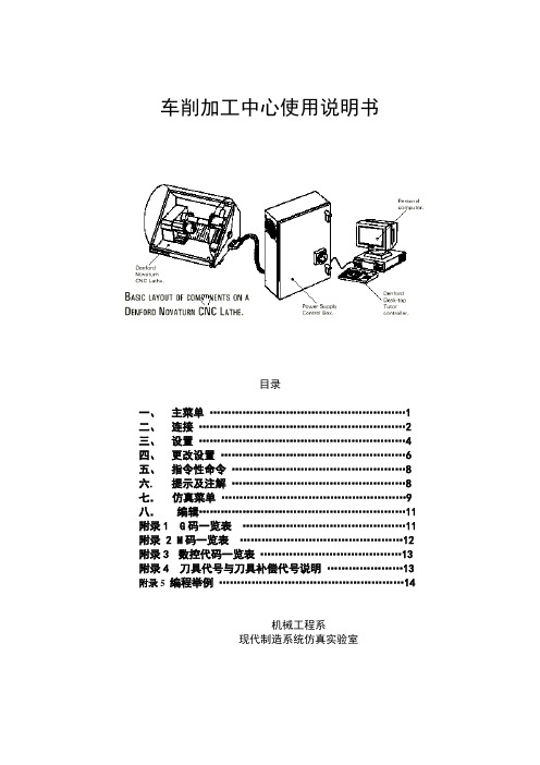
车削加工中心使用说明书目录一、主菜单 (1)二、连接 (2)三、设置 (4)四、更改设置 (6)五、指令性命令 (8)六. 提示及注解 (8)七.仿真菜单 (9)八.编辑 (11)附录1 G码一览表 (11)附录 2 M码一览表 (12)附录3数控代码一览表 (13)附录4刀具代号与刀具补偿代号说明 (13)附录5 编程举例 (14)机械工程系现代制造系统仿真实验室一.主菜单(MAIN MENU)在任意时刻点击”F10”都会击活主菜单。
单独编辑(EDIT ONLY)打开全屏编辑器,包括241个字符横向卷动工具。
在此功能下不能进行仿真,但按下“F9”键,将启动CNC程序的语法检查。
编辑加仿真(EDIT AND SIMULATE )在屏幕上同时打开编辑窗口,仿真窗口与提示窗口。
如果CNC程序行长度超过编辑窗口长度,将增加水平滚动条。
在程序编辑过程中,仿真在任何时候都能进行。
在程序执行后,光标回到它在编辑窗口中的最近更新位置。
单独仿真(SIMULATE ONLY)将仿真窗口设置为全屏。
提示窗口将继续保留在屏幕下部。
如果在程序执行过程中出现错误,编辑和仿真模式将被自动选择,出错的程序码将亮显。
机床控制(MACHINE CONTROL)切换到机床控制,允许刀具选择与设置,并执行用户的CNC程序。
CNC文件(CNC FILES)软件拥有一个非常强大的综合文件系统。
在使用编辑窗口进行文件的调取、储存和列表时,以下几点需要注意。
文件名窗口特性1)要编辑窗口,按ALTER键或在光标在所在行最左端时输入任意数字。
2)用光标键确定光标位置。
3)要列出所有文件列表,按完ALTER键后在按EOB键。
4)所有文件按字母顺序排列。
5)用Cursor(光标)UP/DOWN键和Page(页)UP/DOWN键选择文件。
6)按EOB键确定,按RESET键退出。
程序载入(LOAD)如果当前一个程序正在编辑,系统将提示用户是否要将磁盘中的文件合并在程序中,按’Y’键选择合并,按’N’键选择从编辑窗口清除当前程序并从磁盘载入所选程序。
cnc2000操作手册解读

CNC2000数控系统操作说明目录1 软件简介1.1主界面1.2 运行环境1.3软件要求1.4 安装与初始化文档1.5 CNC2000下图形缩放、图形移动、图形修改、程序修改2数控文件管理与文件编辑2.1数控文件管理2.2数控文件编辑3工作台手动移动的几种方式3.1 电脑键盘手动3.2 电脑操作界面手动3.3 菜单“手动移动与定位”3.4 外接操作面板手动4 程序运行4.1 程序校验4.2 工作台空走(试运行)4.3 运行整个程序4.4 从光标所在行往下执行4.5 运行光标所在行4.6 空走单段运行与修正程序4.7 画线4.8 边框校验5 回零功能6I/O端口测试7参数设置8 数控编程8.1 自动编程8.2 视教编程8.3 手工编程9 工具栏10 其它功能10.1延时参数设置10.2 激光电源电流波形设置10.3激光电源参数设置10.4 断点恢复与断电恢复10.5 矩形零件和圆形零件焊接10.6 相贯线功能10.7 圆管切割11 配置文件设置11.1 中英文界面设置11.2默认参数设置 \Sconfig\Startdef.dat11.3自动编程参数设置文件\Sconfig\table.dat1 软件简介CNC2000数控系统主菜单功能:文件管理、文件编辑、程序运行、手动操作、图形仿真、AutoCAD图形文件转化、查看、帮助等功能。
数控系统界面包括上、下两个用户窗口,可用鼠标拖动两个窗口中间的分界线,改变窗口大小。
上窗口为文件编辑窗口,用于进行文件管理与编辑;下窗口为文件执行窗口。
快捷键F9 暂停F11 回退F12 继续ESC 停止1.1主界面1.2 运行环境CNC2000数控系统软件基于Windows操作系统,可在Win2000、WinXP、Windows98、Windowsme或Windows95下运行。
系统设置:在电源使用方案设置中,将系统等待,关闭监视器,关闭硬盘等全部设置为:从不。
计算机不能按装实时性很强的软件,如病毒实时监控软件等,以免影响CNC系统实时运行。
CTE系列雕刻机说明书_中文片V6.04_配手轮固高板卡V1.4

单击
,弹出如下界面:
该界面显示默认安装路径,一般情况采用默认安装路径,如需更改,可点击
,
弹出如下图所示对话框进行路径选择。
PCUT CTE SERIES USER`S MANUAL
第三章 控制软件介绍
13
如要退回到上一步,可点击
单击
出现如下界面:
按钮。
再次点击
,出现如下界面进行软件安装:
第三章 控制软件介绍
二、雕刻机控制系统的基本要求
基本运行配置:CPU 奔腾 II200Mhz、内存 128 兆以上; 推荐运行配置:CPU 奔腾 III 以上、内存 256 兆、显示器支持 800*600、1024*768。 键盘用 101 键的标准键盘。 推荐软件环境:简体中文 Microsoft Windows 2000。
PCUT CTE SERIES USER`S MANUAL
三、软件安装
打开光盘,双击
第三章 控制软件介绍
11
弹出如下对话框:
选择英文,安装向导将启用英文方式,选择中文, 安装向导将启用中文方式。
点击
按钮,出现如下界面:
第三章 控制软件介绍
12
PCUT CTE SERIES USER`S MANUAL
不可对机器拆卸、修理或整改。
PCUT CTE SERIES USER`S MANUAL
注意 CAUTION 不可用手指触摸刀尖。 此举会导致手指受伤。
机器结构精密,用户请勿自行拆卸;
确保安全的使用方法
3
勿用腐蚀性液体清洗机器部件及键盘;
根据不同的雕刻材料及雕刻深度,选择 合适的刀具,以及设定合适的进刀速 度;
8付 1个 1把 各1把
1块
高速数控机床说明书

高速数控机床说明
书
C u t t i g高速数控机床
说明书
中华人民共和国
科挺自动化有限公司
目录
第一章:安全及注意事项 (02)
第二章:机床的安装 (05)
第三章:机床的操作 (06)
第四章:机床的保养 (13)
第五章:错误排除说明 (15)
第一章:安全及注意事项
为了防止人员受伤或机器受损,安装、使用、维修、检查机床之前,请务必仔细阅读本手册和其它随机资料。
请在具有正确操作机床的能力,熟知安全信息和注意事项之后使用机床。
防止触电,应注意以下事项:
防止火灾,应注意以下事项:
防止损伤,应注意以下事项:
搬运和安装注意事项:。
广泰数控中国人的数控-广泰威达

用户手册
“参数”键二次进入诊断界面,包括 “I/O”、“报警”、“配置”、“返回”等参数;按“参数” 键三次进入螺补界面,包括“X-axis”、“Z-axis”、“清零”、“返回”等参数;在此界面下对 参数分类 ,按下参数设置菜单对应的键即可进入该参数的设置界面。其中参数的切换是 通过按功能软键来实现的,在任何一屏时“返回”或“Esc”键则返回系统主界面。
功能用途
用户手册
字母键 数字键
Hale Waihona Puke 编辑键功能键控制键
进给键 快速键 自定义键
软键 手轮轴选 对比度调节
C H RTA X Y Z L I J K S F M G D P N 0 1 2 3 4 5 6 7 8 9 . - : 用于程序各种指令、 参数的编制,数字键用于输入加工数据、参数值和子菜单的选择
6
用户手册
红色部分表示实际运行速度是最大运行速度的 100%以上,属危险区。 7、手、自动状态显示栏:用于显示系统处于手动还是自动状态,以及手动状态下
的连续、增量、手轮等各状态及其相关信息。 8、M 代码显示栏:用于显示常用的 M 代码的有(无)效情况,其中绿灯表示有效、
红灯表示无效。 9、刀具状态显示栏:用于显示刀具的相关信息。其中图 3.2 从左往右排序来看第
2.4.3 运行环境:
无过量粉尘、酸、碱腐蚀性气体和爆炸性气体,无强电磁干扰。
3
用户手册
第三章 操作说明
3.1 面板分布及开关
主面板
副面板
开关介绍: 开关
紧急停止 (黄/红色) 程序运行 (绿色按钮)
干预开关
按键介绍:
键盘类别
4
图 3.1 面板分布
功能用途 驱动和电机立即停止工作并关主轴、冷却液等,等待抬键重新复位 并初始化值。 运行自动加工程序,同时灯亮。 当置于最左边档时允许进给轴和主轴运行;当置于中间档时,禁止 进给轴运行而允许主轴运转;当置于最右边档时禁止进给轴和主轴 运行。
北京航天数控2100eT编程说明书

安全事项操作者必须在完全熟悉本套说明书及由机床制造厂提供的相关说明的内容后,才能操作机床或编制加工程序。
用户在使用中必须遵守说明书中的规定,这是安全、正确使用CNC装置必需的准备工作。
1概述 (3)2编程 (3)2.1 概述 (3)2.2 零件加工程序 (3)2.3 准备功能 (4)2.4 快速定位(G00) (5)2.5 直线插补(G01) (6)2.6 圆弧插补(G02、G03) (9)2.7 延时程序(G04) (10)2.8 螺纹切削 (11)2.8.1 等距螺纹切削(G32) (11)2.8.2 连续螺纹加工(G32) (13)2.8.3 英制直螺纹、锥螺纹(G36) (14)2.8.4 多头螺纹切削 (15)2.8.5 管螺纹切削指令组 (16)2.9 固定循环编程 (17)2.9.1 螺纹切削循环(G78) (17)2.9.2 单一外径切削循环(G77) (18)2.9.3 单一端面循环(G79) (19)2.9.4 固定循环程序 (20)2.10 绝对值指令和增量值指令(G90、G91) (21)2.11 坐标系设定程序段(G50、G92) (21)2.12 恒线速(G96、G97) (21)2.13 每分钟进给,每转进给(G94、G95) (22)2.14 子程序调用 (22)2.15 坐标指令 (23)2.16 进给速度F (23)2.17 刀具功能(T) (24)2.18 辅助功能M (24)2.19 跳过任选程序段 (25)2.20 C刀补(G41~G42) (26)3补偿功能 (31)3.1 刀具位置补偿 (31)3.2 反向间隙补偿 (31)3.3 丝杠螺距误差补偿 (31)3.3.1 补偿的起始点 (31)3.3.2 线性丝杠螺距误差补偿 (32)4诊断、检测功能 (32)4.1 自诊断功能 (32)4.2 检测功能 (32)系统报警信息处理表 (33)1概述本书由以下几部分组成:1.1概述叙述了本书的组成,相关说明书和阅读本说明书的注意事项。
广州数控 GSK928TE GSK928TC车床数控系统 说明书

GSK928TE/GSK928TC 车床数控系统使 用 手 册前言感谢您选用广州数控设备有限公司生产的GSK928TE/GSK928TC数控系统,本说明书提供了使用本系统所需知识及注意事项。
在系统开始使用之前请注意以下事项:连接好系统的急停按钮。
由于本系统的急停输入采用常闭触点,如不接好急停按钮或错接为常开触点,系统通电后会产生急停报警而不能正常工作,此不属系统故障。
根据刀具的实际安装位置设置好程序参考点,如不设置好参考点就使用回程序参考点功能,则可能发生意外。
此版本说明书适用GSK928TE/GSK928TC数控系统V3.20软件,用户使用GSK928TC数控系统V2.13、V2.23、V3.01软件时,请参阅附录3、附录4、附录5。
为方便表述,本手册中不区分928TE和928TC,以GSK928TE作为通用名称。
用户安全须知在本系统连接使用之前,务必仔细阅读本节安全预防措施。
用户必须遵守这些预防措施以确保人身及设备安全。
用户操作时还必须遵守由本公司提供的说明书指明的相关安全措施。
在完全熟悉本说明书内容后,方可操作本系统。
用户还必须遵守由机床厂商提供的说明书中指明的与机床有关的安全预防措施。
用户必须在完全熟悉本说明书以及由制造厂商提供的相关说明书的内容后才能操作机床或编制程序来控制机床用户安全须知 3Ⅰ. 图形符号定义 (3)Ⅱ. 注意事项 (4)Ⅲ、编程的相关的安全预防措施 (5)Ⅳ、机床操作的注意和警告 (6)。
表示编码器。
表示接触器、继电器线圈。
表示交换。
接线端子。
Ⅱ. 注意事项不可在产品上攀爬或站立,也不可在上面放置重产品的堆放数量有限,不可过多地堆叠在一起,前面板和显示屏应特别参与接线或检查的人员都必须具有做此项工作的充分能力;连接电线不可参数的修改必须在参数设置允许的范围内。
应考虑数控系统的急停开关能在系统发生故障时切断所有1、 坐标系的设定如果没有设置正确的坐标系,尽管指令是正确的,但机床有可能并不按想象的动作运动。
- 1、下载文档前请自行甄别文档内容的完整性,平台不提供额外的编辑、内容补充、找答案等附加服务。
- 2、"仅部分预览"的文档,不可在线预览部分如存在完整性等问题,可反馈申请退款(可完整预览的文档不适用该条件!)。
- 3、如文档侵犯您的权益,请联系客服反馈,我们会尽快为您处理(人工客服工作时间:9:00-18:30)。
第一章前言“GTC2E”车床数控系统采用最新数字信号处理器DSP、大规模可编程门列举阵PLD技术和现场工业级高速CPU,实时控制高速度、高精度;运用320x240点阵LCD液晶显示技术,在整机结构更为紧凑合理。
“GTC2E”数控系统是以车床为代表的二坐标联动、开环控制普及型全数字式数控系统,直接控制交流伺服系统,也可以控制步进伺服系统,符合ISO国际代码标准。
若配置广泰公司生产的二(四)相混合式电机步进伺服系统,实现真正um级控制,其性价比更优,加工精度更高。
所以,“GTC2E”必将成为您最为理想的选择。
“GTC2E”车床数控系统适用于各类仪表车床及其他二坐标联动机床的数控改造和配套。
注意:如是初次使用“GTC2E”数控系统,请仔细阅读说明书各章节的内容,以便更好地有效发挥该系统的功效。
第二章系统技术特性2.1 系统结构•高性能工业级DSP、PLD及专业级CPU•80KB EPROM•80KB SRAM•48K用户内存区,55个工作程序。
•320x240 LCD液晶显示器•轻触式薄膜面板•RS232通讯接口•光电编码器•四/六/八工位电动刀架•高抗干扰开关电源•主轴变频调速•手动操作盒2.2 系统的技术参数•联动轴数:X、Z二轴•脉冲当量:X轴0.0005mm,Z轴0.001mm •最高速度:8000mm/min•加工速度:1-3000mm/min•加工螺距:0.25-24mm•最小输入单位:0.001mm•编程尺寸范围:±7999.999•编程代码:符合ISO-840国际标准•编程坐标系定义:符合ISO-841国际标准•平均无故障时间(MTBF):大于5000小时•机箱防护等级符合IP43的规定2.3 系统功能•自诊断功能:每次开机或复位对DSP、CPU、存贮器、LCD、I/O接口、参数状态、机床坐标、加工程序等进行全方位的诊断;运行中对电源、主轴、限位等进行实时诊断。
•强大的编辑系统:全屏幕编辑,操作得心应手。
•丰富的指令系统:多重循环、固定循环、子程序调用等。
•直线插补、圆弧插补。
•公、英制螺纹、直螺纹、锥螺纹、多头螺纹。
•恒线速切削。
•主轴正转、反转、刹车控制。
•冷却液控制。
•机床自动回基准点。
•补偿功能:反向间隙补偿,刀具换刀自动补偿,加工程度偏置补偿。
刀具半径自动尖角圆弧补偿。
•限位保护:机床硬限位确保在加工过程中的安全性。
•紧急停止:在意外情况下可安全地保护机床和系统。
•实时控制性强:在加工过程中随意升速、降速、干预停止;可实现任意点、任意段的起动和停止。
•通过RS232通讯接口与IBM/PC系列兼容机联机通讯,也可以在“GTC2E”数控系统以及“GT”系列数控系统之间通过连线相互传递加工程序。
机床参数在正常断电和非正常断电时不被破坏。
•丰富的查错功能,对各种操作中的失误均能明确地指出错误的性质并引导改正错误。
2.4 系统运行环境:电源:交流220V (+10%,-15%),频率50Hz±2%。
功率:≤100W。
运行温度5~45℃,相对湿度40-80%。
储运温度0~55℃,相对湿度小于90%(40℃)。
大气压:86-106kpa。
无过量粉尘、酸、碱腐蚀性气体和爆炸性气体,无强电磁干扰。
注意:在自动加工过程中,因意外断电,再次使用本系统时必须回基准点或重新校对加工起点,以免加工尺寸发生变化。
第三章操作说明3.1 面板分布及说明(图 3.0)图3.0 按键介绍:字母键SXZGUWIKDFMPLEFTR用于程序命令和参数编制数字键0123456789.- 用于数据输入和参数设定方向键↑↓→←用于光标移动和手动进给编辑键“插入、删除、上页、下页”用于程序编辑和速度修调功能键“返回”用于操作取消和功能返回“回车”用于功能选择和输入确认“仿真”图形方式快速模拟显示程序加工轨迹。
“编程”进入程序编辑菜单“参数”进入参数设置菜单“偏置”进入加工起点偏置设置菜单“单段”选择手动、自动执行方式,加工中可中停“对刀”确认当前刀在机床坐标系中的位置“刀补”修正换刀误差“快速”用于手动连续高、低速切换控制键“主轴正、主轴反、主轴停”用于主轴的启动和停止“冷却”用于冷却液的启动和停止“基点”X、Z回基准点“换刀”用于电动刀架或排刀的换位“卡盘”用于主轴卡盘的启动和停止“顶针”用于尾座顶针的启动和停止控制钮紧急停止:终止机床一切动作,等待按键抬起干预开关:在加工过程中暂停丝杆和主轴程序运行:执行自动加工程序,同时灯亮3.2 操作主界面整个系统采用一级菜单式操作,直观、方面、快捷,提示信息全面。
系统通电即进入系统主界面(图3.1):图3.1屏幕第一、二行显示当前执行的程序段和下段执行的程序段;第三、四行显示为X、Z轴的机床坐标;第五、六、七行显示的“%99”是当前要加工或正在加工的程序名,“连续”显示自动或手动执行方式,“F0100”是运行速度(自动加工时显示自动加工速度),“V100%”显示执行速度修调倍率;G50显示换刀方式;第八、九行显示的“M10”是主轴卡盘状态,“M3”是主轴状态,“M9”是冷却状态,“T1”是刀架当前刀位,“S3000”显示主轴转速。
菜单的操作:菜单的选择可通过功能键进行。
例如:按“编辑”则进入程序管理系统,可对程序进行编辑、修改、查错、删除、拷贝等工作;按“参数”则进入参数管理系统,可对各类参数进行查阅、修改。
3.3 参数在任何菜单下,按“参数”键,进入参数设置状态(见图3.2)。
图3.2进入子菜单后,反白显示指向当前被选操作项。
可以通过“↑↓←→”选择操作项,按“回车”键进行确认并进入修改状态(此时有光标闪烁)。
操作方式是用“↑↓”方向键移动到要更改的参数处回车,然后键入数据。
输入完毕按“回车”确认,“返回”放弃键入的数据。
操作完用“返回”键退出返回到主功能菜单。
数据输入方法(整个系统方法类同,以下不再赘述):反白显示为当前选择项,有2个以上选择项可以按“↑↓”键进行另选。
修改过程中按“←”键删除前一数据字符;按“返回”键放弃本次输入,保留原数据;按“回车”键确认本次输入,若有下一选择项则自动进入。
输入数据均以mm为单位,“速度”以mm/min为单位,“转速”以n/min为单位,“延时”以s为单位。
3.3.1 基点基点(称参考点)是指在机床安装了机床基准点开关(接触式金属撞块开关或接近开关)的情况下,坐标轴接触到开关位置的坐标值。
系统初始值为0。
其取值范围为0-7999.999mm。
操作举例:设定基点X=280mm,Z=750mm在主菜单状态按“参数”进入参数状态,操作项指向“基点”,最后两行显示:按“回车”键进入基点设置,输入“280”(X=280),按“回车”确认;再输入“750”(Z=750),按“回车”确认。
注意:基点值设置为0时,将封闭本系统的回基点功能。
3.3.2 隙补由于机床传动丝杠和丝杠副之间,或传动链之间存在间隙,当反向运动时,在间隙之间进给就可能不移动,造成误差,这种误差称为反向间隙误差。
隙补就是为了补偿这种误差的数据。
系统初始值为0,其取值范围为0—9.999mm。
在实际加工过程中,由于机械部分的原因,机床床身各部分的间3.3.3 速度为确保伺服电机在可靠范围内运行,可对快速点定位G00速度进行限定,即限定系统最高运行速度,此值对手动回基点也起作用。
系统初始值为4000mm/min。
其取值范围为1000—8000mm/min。
有些机床由于机械原因,可能实际速度达不到4000mm/min,请以实际测量速度再加上10%的保险系数来设置。
在设置过程中,当设定值小于1000时,系统自动默认为1000;当设定值大于8000时,系统自动默认为8000。
3.3.4 延时“延时”是指电动刀架下降反转的锁紧延时时间。
针对不同的电动刀架类型,其值有所区别。
系统初始值为1.5秒,取值范围为0.001-9.999秒。
当其输入值大于5秒时系统默认为5秒;当其为0时,系统也默认为5秒;当最后一位为奇数时(如1.01),系统T8刀位信号接刀架回答信号。
3.3.5 转速“转速”是指主轴转动的最高速度。
系统初始值3000,取值范围为0-9999转/分。
即系统输出+10V模拟电压时的主轴转速。
注意:使用本功能时,机床必须配备主轴变频控制系统。
3.3.6 速率“速率”是指伺服电机升降速的快慢程度,其值越大电机升速越快。
系统初始值5,取值范围为0-9。
如果所配电机为步进电机,可将“速率”设为0-4;如果所配电机为交流伺服电机,可将“速率”设为5-9。
3.3.7 液晶亮度控制在“参数”状态按“P”键后,再按“上页”为增加亮度;按“下页”为减小亮度。
3.4 编程在任何菜单下,按“编程”键,进入程序编制状态(图3.3)。
程序管理采用文件管理方式,本系统可存贮55个程序。
程序编辑采用全屏幕操作方式。
图3.3编程状态包括“编辑”、“拷贝”“删除”、“更名”、“通讯”“信息”六项功能,反白显示“编辑”为当前功能项;通过“←→”键可选择。
中部为程序目录区,显示内存中所有程序名,反白显示“%99”为当前程序;可通过“↑、↓、上页、下页、F”键任意选择其它程序,并以反白方式显示,按“回车”键即进入相应操作状态。
3.4.1 编辑选择“编辑”功能后,系统提示“% ”,此时若直接按回车则编辑当前文件,若输入系统已存在的文件名,则将原文件调出,若输入的文件名不存在,则建立一个新文件。
程序名可以是数字、字母(“N”除外)或混用,长度为2位。
程序名输入法:输入过程按“ ”键删除前键,按“返回”放弃。
若输入一位按“回车”键则自动在前面加“0”;若无任何输入直接按“回车”则默认为当前文件名,无当前文件时默认为“%00”。
本系统程序名不允许重名。
输入文件名后便进入全屏幕编辑系统(图3.4)。
图3.4屏幕底行提示所编辑的程序名和编辑状态(“插入”键进行切换)。
中部左面为行号区,如:N0000,用户不能操作,由系统自动产生;右面为程序内容区,即用户可操作区。
1)光标定位:按“↑↓←→”键可将光标移到程序内容的任意位置。
按“上页”键光标到上页。
按“下页”键光标到下页。
在改写状态按“回车”键光标到下行行首。
按“N”键(行间操作),可进行如下操作:•按“↑”键:光标到到本屏屏首。
•按“↓”键:光标到到本屏屏尾。
•按“←”键:光标到到本行行首。
•按“→”键:光标到到本行行尾。
•按“上页”:光标到到程序首。
•按“下页”:光标到到程序尾。
•按“G”键:输入行号后光标定位到指定行。
行号输入方法(全系统输入方法相同):输入四位数字(前0可以不输入),输入过程中按“←”键删除前键,按“返回”键放弃返回,按“回车”键确认;若四位为缺省值时,默认为当前行号。
2)字符修改:改写状态下,在光标处直接输入所需字符。