Zigbee组网实验之Sample App
Zigbee建网和入网过程实验

6.2 Zigbee建网和入网过程实验本实验通过Sample App这个例子实现数据在ZigBee网络中的简单传输。
要求掌握网络组建及协议分析仪的使用方法。
6.2.1 实验目的与器材1)实验目的◆熟悉zigbee协议的三种设备建网时所担任的角色;◆学习Z-Stack2007/PRO协议栈中协调器如何建立网络;◆学习Z-Stack2007/PRO协议栈中路由和终端如何加入网络;◆学习TI官方提供的抓包工具(Sniffer)的应用及协议分析。
2)实验器材◆3个CC2530开发套件(1个协调器模块,2个路由器模块);6.2.2 实验原理与步骤1)硬件介绍CC2530开发套件如实验一中的硬件介绍,这里就不再陈述。
2)实验原理1 设备的分类ZigBee网络只支持两种设备:1)全功能设备(FFD Full Function Device)2)精简功能设备(也叫半功能设备 Reduced Function Device)两者的比较:其中FFD设备能够提供MAC层的所有服务,可充当任何ZigBee节点,不仅可以接收发送数据,还具有路由功能,因此可以接收子节点;而RFD只能提供部分的MAC层服务,只能充当子节点,只负责将采集到的数据发送给协调器和路由器节点,本身并不具有路由功能,因此不能接收子节点信息,RFD之间的通信只能通过FFD来完成。
ZigBee标准在此基础上定义了三种节点:ZigBee协调器(Coordinator)、ZigBee路由器(Routers)、ZigBee终端(End Device)2 所使用的设备所用的ZigBee设备都具有连接网络和断块网路的功能。
ZigBee协调器和路由器都具有以下附加功能:1)允许设备以如下方式连接网路:① MAC(Medium Access Control)层的连接命令。
②应用层的连接请求2)允许设备以如下方式断开网络;① MAC层的断开命令②应用层的断开命令③对逻辑网络地址的分配④维护邻居设备3 组建网络组建一个网状的ZigBee网络包括两个步骤:网络的初始化和节点加入网络;而节点加入网络又有两个步骤:通过协调器加入网络和通过已有节点入网。
Sample-APP的实验现象及功能

This application isn't intended to do anything useful, it is intended to be a simple example of an application's structure. This application sends it's messages either as broadcast or broadcast filtered group messages. The other (more normal)message addressing is unicast. Most of the other sample applications are written to support the unicast message model. Key control:SW1: Sends a flash command to all devices in Group 1.SW2: Adds/Removes (toggles) this device in and out of Group 1. This will enable and disable the reception of the flash command.Initially, place all of the devices on the same table or work area. You will establish the network while the devices are all in view of each other. Later, you can experiment with various distances and different power-up sequences.After each of the CC2530EM boards has been programmed with the “Demo” configuration of SampleApp, one of the boards needs to be designated as a ZigBee Coordinator. This is done by placing a jumper across pins on the P18 jumper block. On Rev 1.3 boards, the jumper connects pins 7-9 (below, left). On Rev 1.7 boards, the jumper connects pins 9-11 (below, right). Make sure that only one SmartRF05EB board has a jumper on P18.Initially, begin execution of the programmed SampleApp by applying power to the device that is configured as the ZigBee Coordinator. This device performs a scan of the programmed ZigBee channel (see Section 7), temporarily flashing LED1. Once the device successfully starts up a network, LED3 (yellow) will turn on and LED1 will stop flashing. Next, power up a ZigBee Router device (no jumper on P18). This device will now scan the programmed ZigBee channel for a network, temporarily flashing LED1. Once it joins the network started by the Coordinator, LED3 (yellow) will be turned on and LED1 will stop flashing. If desired, turn on more Router devices and each of them will turn on their LED3 after joining the network.Once the network has been formed, the SampleApp will provide a very simple demonstration of ZigBee wireless communication. The sample application performs the following three functions:Periodic (about 5 seconds) broadcast of a message to all network devicesWhen button SW1 is pressed, broadcast of a message to devices subscribed to Group 1Wh en button SW2 is pressed, toggles a devices’ membership in Group 1When each SampleApp device starts up, it is subscribed to Group 1 and will receive and process messages sent to Group 1 from any other device. In this demonstration, a device will flash its LED1 (green) when a Group 1 message is received. So, when the network is initially started up, pressing button SW1 on any device will broadcast a message, causing all of the other devices to flash their LED1. Pressing button SW2 on a device toggles that device’s membership in Group 1, allowing the user to enable/disable LED1 flashing on that device.The discussion above assumes each device has been programmed and disconnected from the development PC. When necessary, a target device can be controlled from the IAR IDE, providing for standard debugging features such as breakpoints, single-stepping, viewing of memory and register contents, etc.Energy LevelThe Coordinator will start a network on a selected channel only if the energy level on that channel is below a threshold value. The threshold value is set to -45dBm and can be modified by changing the MAX_SCAN_ENERGY definition in the mac_scan.c file (available only with TIMAC and Z-Stack source distributions). The value of this parameter minus 83 gives the maximum tolerated energy level in dBm. To ensure that the Coordinator will always find a suitable channel to start a network on, it is recommended that more than one channel is selectedIEEE Address SelectionEvery ZigBee device requires a unique 64-bit IEEE address. Z-Stack uses the following four-level hierarchy to determine the IEEE address that will be used for the device when it operates:Read from Z-Stack non-volatile memoryLook-up from Secondary IEEE locationLook-up from Primary IEEE locationCreate temporary using random number generationUnder normal circumstances, when a Z-Stack device boots up, it reads the IEEE address from non-volatile memory (NV) that was stored during a previous “run” of the device. NV memory retains parameters, including the IEEE address, for occasions when the device resets, typically after a power failure. The IEEE address in NV memory gets saved under 3 possible scenarios – initially from steps 2-3 of the hierarchy listed above, or later by delivery from an external source (such as via serial I/O from a PC-hosted program like Z-Tool).During a device reset process, if the “read from NV memory” operation fails, Z-Stack will first attempt to find an IEEE address at the Secondary IEEE address location (step 2). If that fails, it will then attempt to find an address in the Primary IEEE address location (step 3). Finally, if that fails, Z-Stack will generate a “temporary” address using random numbers (step 4). In steps 2 and 3, the IEEE address gets written to NV memory – on the next device reset this address will be read from NV memory (step 1). In a development environment (NV_RESTORE not used), the temporary IEEE address is not written to NV memory, so each time the device gets reset it will have a different IEEE address than before.The Secondary IEEE address location is found on the last page of the CC2530 flash memory, at an offset of 0x0018 bytes from the last memory address. For a 256-Kbyte device, the IEEE address can be commissioned at 0x3FFE8-0x3FFEF. This address location is provided for the user to override the TI pre-programmed Primary address “at the factory”. Device programming tools that work with Z-Stack are set up to preserve IEEE addresses stored at this location.During a device reset process, if an IEEE address cannot be found in NV memory or in the Secondary IEEE address location, Z-Stack will attempt to read a TI pre-programmed Primary IEEE address from locations 0x00C-0x013 of the device “information memory”. In the rare event that the CC2530 device does not have a pre-programmed Primary IEEE address, a temporary 64-bit address beginning with 0xF8 will be generated using the system’s random number generator.Z-Stack permits the IEEE address to be updated in NV memory via the standard NV_Write API. This allows developers to change the address at their discretion, using Z-Tool or another equivalent mechanism. In the production environment, it is probably advisable to disable this capability since a deployed ZigBee device should not be allowed to change its IEEE address.。
zigbee LQI、RSSI、丢包率等关系实验1

4.6 zigbee LQI、RSSI、丢包率等关系实验无线传感器网络环境的复杂多变对ZigBee网络的自组织性提出了挑战,在实际的网络部署中,链路质量指示(LQI)、信号强度(RSSI)、丢包率等都对网络的调度分配与优化具有重要意义,LQI、RSSI在ZigBee标准中已经有了良好的定义,而且在ZigBee芯片上都提供了直接的支持,通过Z-Stack协议栈能够方便的获得。
4.6.1 实验目的与器材1)实验目的本实验将利用Z-Stack2007协议栈提供的API获取LQI、RSSI等数据信息,通过多组测试进行统计分析。
由于无法模拟复杂的网络环境,主要在实验5.6的基础上,通过修改节点的发射功率以及增加干扰节点来影响统计的终端节点与协调器节点之间的通信,并由此分析发射功率对LQI、RSSI、丢包率等的影响,给实际的网络部署提供具有参考意义的数据信息,同时也可以利用现有代码将节点直接部署在需要建网的地方进行测试分析。
2)实验器材3个CC2530开发模块(1个协调器节点,1个终端节点,1个干扰节点);4.6.2 实验原理与步骤1)LQI、RSSI介绍1 链路质量指示(LQI)LQI即链路质量指示,在ZigBee标准中规定的链路质量指示用于指示接收数据包的质量,为网络层或应用层提供接收数据帧时无线信号的强度和质量信息,它要对信号进行解码,生成的是一个信噪比指标。
LQI的取值是0x00~0xff,分别表示接收到的信号最差质量(0x00)到最好质量(0xff)。
2 接收信号强度(RSSI)RSSI(Received Signal Strength Indicator)是接收信号的强度指示,它的实现是在反向通道基带接收滤波器之后进行的。
同时可以利用RSSI来进行统计信息进而实现定位功能。
RSSI 一般可从芯片直接获取:RSSI与LQI的关系:RSSI =-(81-(LQI*91)/255)RSSI与d(距离)的关系:2)程序流程1协议栈中,RSSI、LQI获取:在测试代码中主要通过sendReport()函数完成周期性的代码发送SampleApp_MessageM SGCB()完成在接收到数据包后进行的处理,而获得的数据包中本身就包含了RSSI和LQI 值,通过osal_msg_receive()函数进行获取解析,并形成afIncomingMSGPacket_t结构体类型:typedef struct{osal_event_hdr_t hdr; /* OSAL Message header */uint16 groupId; /* Message's group ID - 0 if not set */uint16 clusterId; /* Message's cluster ID */afAddrType_t srcAddr; /* Source Address, if endpoint is STUBAPS_INTER _PAN_EP,it's an InterPAN message */uint16 macDestAddr; /* MAC header destination short address */uint8 endPoint; /* destination endpoint */uint8 wasBroadcast; /* TRUE if network destination was a broadcast address */uint8 LinkQuality; /* The link quality of the received data frame */uint8 correlation; /* The raw correlation value of the received da ta frame */int8 rssi; /* The received RF power in units dBm */uint8 SecurityUse; /* deprecated */uint32 timestamp; /* receipt timestamp from MAC */afMSGCommandFormat_t cmd; /* Application Data */} afIncomingMSGPacket_t;因此在SampleApp_MessageMSGCB()函数中,通过调用传入的参数afIncomingMSGPac ket_t *pkt即接收到的数据包,调用即可获得。
Zigbee组网实验报告
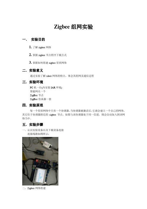
Zigbee组网实验一.实验目的1.了解zigbee网络2.掌握zigbee节点程序下载方式3.掌握如何组建zigbee星状网络二.实验意义通过实验了解zibee网络的特点,体会其组网及通信过程三.实验环境PC机一台(内安装IAR环境)智能网关一个ZigBee节点ZigBee仿真器一套四.实验原理每一个星状网络中只有一个协调器,当协调器被激活后,它就会建立一个自己的网络。
其它位于协调器附近的zigbee节点,如果与该协调器处于同一信道,则会自动加入到该网络当中。
五.实验步骤一、认识实验设备以及下载设备连接连接线路如图所示:二、Zigbee网络组建1、协调器下载协调器在本套智能家居系统中担任信息收集与传输的工作,它和每个ZigBee模块进行无线通讯,并将信息传送给智能网关,同时也将网关的控制指令发送给各个模块。
我们首先将一个ZigBee模块下载成协调器,具体步骤如下:(1)打开“\实验程序\协调器\Projects\zstack\Samples\collector SimpleApp 1.25\ CC2430DB\SimpleApp.eww”。
如图1-6所示:(2)不同的实验小组选择自己所分配的信道。
点击左侧的文件导航栏,找到tools文件夹,打开其中的文件f8wConfig.cfg,找到自己小组的信道,将行的注释去掉,并且确认其他各个信道代码均为注释状态。
更改完信道之后,在菜单栏中选择Project\Rebuild All进行编译,编译完成后生成的HEX 文件保存在\实验程序\协调器\Projects\zstack\Samples\collectorSimpleApp1.25\CC2430DB\SimpleCollectorEB\Exe 中。
(3)更改完信道之后,在菜单栏中选择Project\Rebuild All进行编译,编译完成后生成的HEX文件保存在\实验程序\协调器\Projects\zstack\Samples\collectorSimpleApp1.25\CC2430DB\SimpleCollec torEB\Exe中;(4)打开smartRF下载软件,如图所示,按照图将下载设备的各个线连接好,之后按一下下载器(也就是白色盒子)上面的黑色按钮,则下载界面中将会识别到要与下载器相连接的zigbee模块芯片,如图所示,对相关条件进行勾选;2.其它zigbee终端节点的下载Zigbee终端节点在上电后自动加入到处于同一信道的zigbee协调器所组建的zigbee网络当中。
实验三ZigBee协议实验
实验三ZigBee协议实验实验三ZigBee协议实验【实验目的】1、了解ZigBee 2007 协议栈操作系统的工作机制2、了解ZigBee 2007 协议栈应用程序框架的工作机制3、了解ZigBee 广播通信的原理4、掌握在ZigBee 网络中进行广播通信的方法5、了解ZigBee 组播通信的原理6、掌握在ZigBee 网络中进行组播通信的方法【实验设备】1、装有IAR 开发环境的PC 机一台2、物联网开发设计平台所配备的基础实验套件一套3、下载器一个【实验要求】1、广播通信实验要求:在GenericApp 应用程序框架下,编写程序,使得协调器周期性以广播的形式向终端节点发送数据“Coord Broadcast”(每隔5s广播一次),终端节点收到数据后,使开发板上的LED红灯状态翻转(如果LED原来是亮,则熄灭LED;如果LED原来是灭的,则点亮LED),同时向协调器发送字符串“EndDevice received!”,协调器收到终端节点发回的数据后,通过串口输出到PC机,用户可以通过串口调试助手查看该信息。
设备:一个协调器,二个终端2、组播通信实验要求:在GenericApp 应用程序框架下,编写程序,使得协调器周期性的以组播的形式向路由器发送数据“Group1”(每隔5s发送组播数据一次),组内的路由器收到数据后,使开发板上的红色LED状态翻转(如果LED原来是亮,则熄灭LED;如果LED原来是灭的,则点亮LED),同时向协调器发送自己的网络短地址和字符串“Router received!”,协调器收到路由器发回的数据后,通过串口输出到PC 机,用户可以通过串口调试助手查看该信息。
设备:一个协调器,三个路由器,其中两个加入组,一个不加入组。
【实验原理】1.无线数据传输模式: 组播和广播(1)组播:主机之间“一对一组”的通讯模式,也就是加入了同一个组的主机可以接受到此组内的所有数据,网络中的交换机和路由器只向有需求者复制并转发其所需数据。
cc2430 zigbee模块的 SimpleApp 例子解读-2 程序分析
学习zigbee入门SimpleApp 例子解读-2 程序分析:灯开关灯实验:开关设备通过发送命令切换控制设备的状态,并通过指示灯的状态变化反应操作是否成功。
在SimpleApp,SimpleController.c(灯管理器设备)按键处理函数zb_HandleKeys中,当SW1被按下,它将使设备作为协调器使用;期间按下SW2,它将是该设备作为路由器启动。
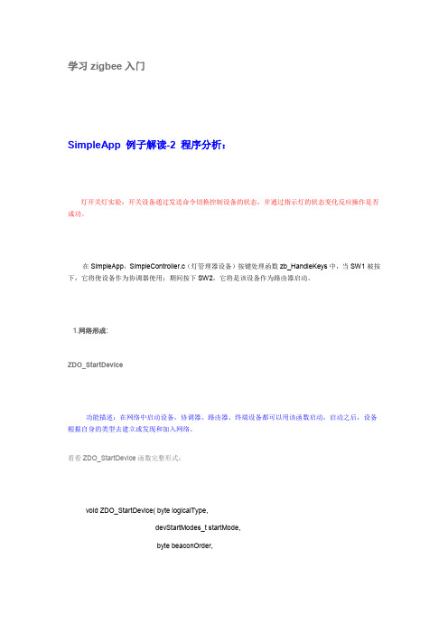
1.网络形成:ZDO_StartDevice功能描述:在网络中启动设备,协调器、路由器、终端设备都可以用该函数启动,启动之后,设备根据自身的类型去建立或发现和加入网络。
看看ZDO_StartDevice函数完整形式:void ZDO_StartDevice( byte logicalType,devStartModes_t startMode,byte beaconOrder,byte superframeOrder ){ZStatus_t ret;ret = ZUnsupportedMode;#if defined(ZDO_COORDINATOR) //--条件编译语句,选择性的启动协调器if ( logicalType == NODETYPE_COORDINATOR ) //--逻辑类型,协调器{if ( startMode == MODE_HARD ) //--启动模式,硬件启动(软件启动无线龙注释暂不启动){devState = DEV_COORD_STARTING; //--协调器启动ret = NLME_NetworkFormationRequest( zgConfigPANID, zgDefaultChannelList, //--网路形成请求zgDefaultStartingScanDuration, beaconOrder,superframeOrder, false );}else if ( startMode == MODE_RESUME ) //--恢复{// Just start the coordinatordevState = DEV_COORD_STARTING;ret = NLME_StartRouterRequest( beaconOrder, beaconOrder, false ); //--路由启动请求}else{#if defined( LCD_SUPPORTED ) //--液晶显示支持(--条件编译)//HalLcdWriteScreen( "StartDevice ERR", "MODE unknown" );ClearScreen();Print8(HAL_LCD_LINE_1,10,"StartDevice ERR",1);Print8(HAL_LCD_LINE_2,10,"MODE unknown",1);#endif}}#endif // !ZDO_COORDINATOR#if !defined ( ZDO_COORDINATOR ) || defined( SOFT_START ) //--不是协调器,软件启动if ( logicalType == NODETYPE_ROUTER || logicalType == NODETYPE_DEVICE )//--逻辑类型,路由,终端设备{if ( (startMode == MODE_JOIN) || (startMode == MODE_REJOIN) ) //--启动模式,加入,再加入{devState = DEV_NWK_DISC;#if defined( MANAGED_SCAN ) //--管理扫描ZDOManagedScan_Next(); //--调用管理扫描ret = NLME_NetworkDiscoveryRequest( managedScanChannelMask,BEACON_ORDER_15_MSEC );//--网络发现请求#elseret = NLME_NetworkDiscoveryRequest( zgDefaultChannelList, zgDefaultStartingScanDuration ); #endif}else if ( startMode == MODE_RESUME ) //--恢复{if ( logicalType == NODETYPE_ROUTER ) //--路由{ZMacScanCnf_t scanCnf; //--扫描确认devState = DEV_NWK_ORPHAN; //--设备已经失去了其母节点的信息/* if router and nvram is available, fake successful orphan scan *///--如果路由器和NVRAM可用,假成功的孤儿扫描scanCnf.hdr.Status = ZSUCCESS;scanCnf.ScanType = ZMAC_ORPHAN_SCAN;scanCnf.UnscannedChannels = 0;scanCnf.ResultListSize = 0;nwk_ScanJoiningOrphan(&scanCnf);ret = ZSuccess;}else //--终端节点{devState = DEV_NWK_ORPHAN;ret = NLME_OrphanJoinRequest( zgDefaultChannelList, //--再加入请求zgDefaultStartingScanDuration );}}else{#if defined( LCD_SUPPORTED )// HalLcdWriteScreen( "StartDevice ERR", "MODE unknown" );Print8(HAL_LCD_LINE_1,10,"StartDevice ERR",1);Print8(HAL_LCD_LINE_2,10,"MODE unknown",1);#endif}}#endif //!ZDO COORDINATOR || SOFT_STARTif ( ret != ZSuccess )osal_start_timerEx(ZDAppTaskID, ZDO_NETWORK_INIT, NWK_RETRY_DELAY );}2、绑定:zb_BindDevice ----已知扩展地址的绑定(1.4.3-1.2.1把已知和未知的结合起来了,还结合了绑定移除)---未知设备扩展地址的绑定---移除绑定//--设备建立绑定和移除绑定信息相关void zb_BindDevice ( uint8 create, //--是否创建绑定,ture为创建,false则解除uint16 commandId, //--命令ID,基于某种命令的绑定uint8 *pDestination ) //--指向扩展地址的指针{zAddrType_t destination; //--目的设备的类型uint8 ret = ZB_ALREADY_IN_PROGRESS; //--if ( create ) //--是否创建绑定,ture为创建,false则解除{if (sapi_bindInProgress == 0xffff) //--绑定地址为0xffff{if ( pDestination ) //--已知扩展地址的绑定,即*pDestination为非NULL{destination.addrMode = Addr64Bit; //--目的地址模式,长地址osal_cpyExtAddr( destination.addr.extAddr, pDestination );//--把扩展地址复制到extAddr中//--通过APSME_BindRequest创建绑定请求ret = APSME_BindRequest( sapi_epDesc.endPoint, commandId,&destination, sapi_epDesc.endPoint );if ( ret == ZSuccess ){// Find nwk addr //--发现网络地址,得到被绑定设备的短地址ZDP_NwkAddrReq(pDestination, ZDP_ADDR_REQTYPE_SINGLE, 0, 0 );osal_start_timerEx( ZDAppTaskID, ZDO_NWK_UPDATE_NV, 250 );}}else{ret = ZB_INVALID_PARAMETER;destination.addrMode = Addr16Bit;destination.addr.shortAddr = NWK_BROADCAST_SHORTADDR;if ( ZDO_AnyClusterMatches( 1, &commandId, sapi_epDesc.simpleDesc->AppNumOutClusters,sapi_epDesc.simpleDesc->pAppOutClusterList ) ){// Try to match with a device in the allow bind mode --匹配一个允许绑定模式下的设备ret = ZDP_MatchDescReq( &destination, NWK_BROADCAST_SHORTADDR,sapi_epDesc.simpleDesc->AppProfId, 1, &commandId, 0, (cId_t *)NULL, 0 );}else if ( ZDO_AnyClusterMatches( 1, &commandId, sapi_epDesc.simpleDesc->AppNumInClusters,sapi_epDesc.simpleDesc->pAppInClusterList ) ) {ret = ZDP_MatchDescReq( &destination, NWK_BROADCAST_SHORTADDR, sapi_epDesc.simpleDesc->AppProfId, 0, (cId_t *)NULL, 1, &commandId, 0 );}if ( ret == ZB_SUCCESS ){// Set a timer to make sure bind completes --设置一个时间,确保绑定完成。
zigbee组网实验报告

zigbee组网实验报告
《Zigbee组网实验报告》
近年来,随着物联网技术的迅猛发展,各种无线传感器网络的研究和应用也日
益受到关注。
其中,Zigbee作为一种低功耗、低成本的无线传感器网络技术,
被广泛应用于智能家居、工业自动化、农业监测等领域。
为了更好地了解Zigbee组网技术的性能和应用,我们进行了一系列的实验。
首先,我们搭建了一个小型的Zigbee传感器网络,包括一个协调器和若干个终端节点。
通过Zigbee协议栈的支持,我们成功实现了这些节点之间的通信和数据传输。
在实验过程中,我们发现Zigbee组网具有较高的稳定性和可靠性,即使在复杂的环境中也能够保持良好的通信质量。
其次,我们对Zigbee组网的能耗进行了测试。
结果显示,由于Zigbee采用了
低功耗的通信方式,因此整个传感器网络的能耗非常低,能够满足长期监测和
控制的需求。
这使得Zigbee成为了很多物联网应用的首选技术之一。
另外,我们还对Zigbee组网的网络拓扑结构进行了研究。
通过改变节点之间的布局和距离,我们发现Zigbee能够自动调整网络拓扑结构,保持良好的网络覆盖和通信质量。
这为实际应用中的网络规划和优化提供了重要的参考。
总的来说,我们的实验结果表明,Zigbee组网技术具有很好的性能和应用前景。
它不仅在能耗方面表现优异,而且在通信稳定性和网络拓扑结构方面也具有很
强的适应能力。
我们相信,在未来的物联网应用中,Zigbee将会发挥越来越重
要的作用。
希望我们的实验报告能够为相关研究和应用提供一定的参考和借鉴。
zigbee组网实验报告
zigbee组网实验报告ZigBee组网实验报告引言:ZigBee是一种低功耗、低速率、低成本的无线通信技术,被广泛应用于物联网领域。
本实验旨在通过搭建ZigBee网络,探索其组网原理和应用。
一、实验背景随着物联网的快速发展,各种智能设备的出现使得人们的生活更加便捷和智能化。
而ZigBee作为一种独特的无线通信技术,具有低功耗、低成本和可靠性强的特点,成为物联网领域的重要组成部分。
二、实验目的1.了解ZigBee组网的基本原理和拓扑结构;2.搭建ZigBee网络,实现设备之间的通信;3.探索ZigBee在物联网领域的应用。
三、实验步骤1.准备工作在实验开始前,需要准备一些硬件设备,包括ZigBee模块、开发板、传感器等。
同时,还需要安装相应的软件开发环境。
2.搭建ZigBee网络首先,将ZigBee模块插入开发板,连接电源并进行初始化设置。
然后,通过软件开发环境,配置网络参数,包括网络ID、信道等。
接下来,将各个设备逐一加入网络,形成一个完整的ZigBee网络。
3.通信测试完成网络搭建后,进行通信测试。
通过发送指令或传感器数据,验证设备之间的通信是否正常。
同时,还可以进行数据传输速率测试,评估网络的性能。
四、实验结果与分析经过实验,成功搭建了一个ZigBee网络,并实现了设备之间的通信。
通过测试发现,ZigBee网络具有较低的功耗和较高的可靠性,适用于物联网领域的各种应用场景。
五、实验总结ZigBee作为一种重要的无线通信技术,具有广泛的应用前景。
通过本次实验,我们深入了解了ZigBee组网的原理和应用,并通过实际操作掌握了搭建ZigBee网络的方法。
这对我们进一步研究和应用物联网技术具有重要意义。
六、展望在未来,随着物联网的不断发展,ZigBee网络将在更多的领域得到应用。
例如智能家居、智能医疗、智能交通等,ZigBee技术将为这些领域带来更多的便利和创新。
结语:通过本次实验,我们对ZigBee组网技术有了更深入的了解,并体验了其在物联网领域的应用。
- 1、下载文档前请自行甄别文档内容的完整性,平台不提供额外的编辑、内容补充、找答案等附加服务。
- 2、"仅部分预览"的文档,不可在线预览部分如存在完整性等问题,可反馈申请退款(可完整预览的文档不适用该条件!)。
- 3、如文档侵犯您的权益,请联系客服反馈,我们会尽快为您处理(人工客服工作时间:9:00-18:30)。
Zigbee组网实验之Sample App
/
佳杰科技开发套件,最便宜、最详细、最好的Zigbee开发套件。
1.实验设备:
Q2530SB开发底板(V1.1以上版本)2块
RF2530N射频板2块
天线(非必要,影响传输距离)2根
SmartRF04EB仿真器带USB线和仿真器接头线1个
电池盒有电池一个(负责供电)
2.硬件连接说明
射频板RF2530N分别连接底板Q2530SB
仿真器USB线连接电脑和其中一块底板
电池盒连接另外一块底板、保证系统都正常供电
3.实验步骤及效果
1.打开实验代码:在路径Texas Instruments\ZStack-CC2530-
2.
3.0-1.
4.0\Projects\zstack\
Samples\SampleApp\CC2530DB下鼠标双击打开文件SampleApp.eww
2.在应用层APP文件夹中找到SampleApp.c文件,找到函数SampleApp_HandleKeys并双
击打开。
3.将函数中的代码做以下修改
if ( keys & HAL_KEY_SW_1 )
{
/* This key sends the Flash Command is sent to Group 1.
* This device will not receive the Flash Command from this
* device (even if it belongs to group 1).
*/
SampleApp_SendFlashMessage( SAMPLEAPP_FLASH_DURATION );
}
改为
if ( keys==0x20 )
{
/* This key sends the Flash Command is sent to Group 1.
* This device will not receive the Flash Command from this
* device (even if it belongs to group 1).
*/
SampleApp_SendFlashMessage( SAMPLEAPP_FLASH_DURATION );
}
4.保存修改后的代码
5.在Workspace中选择EndDeviceEB-Pro,然后直接点击Debug图标编译下载
●下载完后除了电源指示灯之外都熄灭
点击go图标运行程序
●D1 D2亮D3闪烁说明已经建立了网络
6.在Workspace中选择CoordinatorEB-Pro,然后直接点击Debug图标编译下载
●下载完后除了电源指示灯之外都熄灭
点击go图标运行程序
●D1 D2亮D3闪烁说明已经建立终端节点
7.点击终端节点的S0按键
●协调器节点灯D1开始闪烁4次后恢复亮的状态(成功)
4.实验分析
1.实验目的。