墙暖说明书
高压氢气壁墙空调与加暖系统所有者手册说明书

Models:LIVS09HP115V1B LIVS12HP115V1B LIVS09HP230V1B LIVS12HP230V1B LIVS18HP230V1B LIVS24HP230V1B LIVS30HP230V1B LIVS36HP230V1BHIGH-WALL DUCTLESSAIR CONDITIONING &HEATING SYSTEM OWNER’S MANUALTable of ContentsIntroduction . . . . . . . . . . . . . . . . . . . . . . . . . . . . . . . . . . . . . . . . . . .2Nomenclature . . . . . . . . . . . . . . . . . . . . . . . . . . . . . . . . . . . . . . . . . .2Safety Precautions . . . . . . . . . . . . . . . . . . . . . . . . . . . . . . . . . . . .3-4Installation Schematic . . . . . . . . . . . . . . . . . . . . . . . . . . . . . . . . . . . 5System Functions . . . . . . . . . . . . . . . . . . . . . . . . . . . . . . . . . . . . .6-8Operation of Wireless Remote Contoller . . . . . . . . . . . . . . . . . .9-16Care and Cleaning . . . . . . . . . . . . . . . . . . . . . . . . . . . . . . . . . . . . .17Troubleshooting . . . . . . . . . . . . . . . . . . . . . . . . . . . . . . . . . . . .18-19Energy Saving Tips . . . . . . . . . . . . . . . . . . . . . . . . . . . . . . . . . . . . .20Warranty . . . . . . . . . . . . . . . . . . . . . . . . . . . . . . . . . . . . . . . . . . .BackThank you for choosing aLivo Heat Pump System!You can feel confident in your selection because the same pride in craftsmanship and engineering knowledge that goes into millions of other Gree installed products worldwide has gone into your unit.Please read this owner’s manual carefully before operation and retain it for future reference.INTRODUCTIONSuperior Design for Superior PerformanceGree’s Livo Inverter-driven, Mini Split Heat Pumps are beautifully designed to deliver effective cooling or heating, while fitting unobtrusively into any decor. The indoor unit’s aesthetically pleasing, minimalist design blends nicely in any home or office.Your Livo unit offers quiet, energy-efficient comfort, powered by Gree’s famous G10 Inverter technology. To speed the process of bringing conditioned air exactly where you want it, the unit features both horizontal and vertical air flow control. Customizable mode controls allow you to adjust fan speeds, select sleep-time settings and more, all through the easy-to-use wireless remote controller, or an optional Wired Tether Controller.There’s even a Turbo, Power Failure Memory and other advanced features to make the Livo system even more versatile, for year-round comfort and energy savings. NOMENCLATUREPlease read the following before operation.symbol on the unit and in instructions or manuals, be alert to the potential for personal injury. Understand these signal words: DANGER, WARNING, and CAUTION. These words are used with the safety-alert symbol.DANGER identifies the most serious hazards which will result in severe personal injury or death.WARNING signifies hazards which could result in personal injury or death. CAUTION is used to identify unsafe practices which may result in minor personal injury or product and property damage.NOTE is used to highlight suggestions which will result in enhanced installation, reliability, or operation.NOTE:Your actual air conditioning & heating system and related devices may differ from the images shown in this manual.Please read the following before operation.:::::Front Panel DisplayThe front panel on the Livo indoor unit contains system status lights and easy-to-read LED display. NOTE:The indoor unit display panel can be turned ON or OFF via the LIGHT buttonon the remote controller. See "LIGHT" button description for more detail.INSTALLATION SCHEMATIC1. 2.3.Air Filter4. 5.6.8. 9.34WHISPER QUIETNot only are the Gree systems energy efficient but they are quiet too. Livo High-Wall units operate with sound pressure levels starting as low as 28 dB(A).MULTI FAN SPEEDSWhether operating in either Cooling or Heating mode, the indoor fan can be set to your choice of four different speeds (Low, Medium, High or Turbo) to achieve maximum comfort. INTELLIGENT PRE-HEATINGThe Livo system guards against the annoying cool air blown into the room in heating mode. The system constantly monitors the discharge air temperature. It will delay the indoor fan until the indoor coil has warmed up to prevent blowing uncomfortable cool air into the room.I FEEL MODEThe unit will sense room temperature at the remote controller instead of at the indoor unit during cooling mode. It then adjusts airflow and temperature accordingly for the ultimate in personal comfort control and energy savings.ADJUSTABLE AIRFLOWThe Livo system has a bi-directional airflow control for maximum comfort. The indoor unit has adjustable vertical swing louvers and can be set in multiple discharge directions from the wireless remote controller.TURBO MODEUse Turbo Mode for situations where you wish to achieve the desired room temperature in the shortest possible time. This mode runs the unit at ultra high speeds for quickest results. FREEZE GUARDRoom Freeze Guard protection will automatically keep the room temperature from getting too cold, where water pipes might freezeTIMER MODEThe unit can be programmed to turn ON or OFF after a specific amount of time. The time period is adjustable between one half and 24 hours.MODE BUTTONThe unit can be set to five different operating modes: HEAT, COOL, DRY, FAN ONLY and AUTO. NOTE:AUTO MODE has fixed setpoints of 68° F heating and 77° F cooling, whichare not adjustable. The system will automatically select heating or cooling to maintain room temperature within this band.SLEEP MODEThe Livo offers a Sleep Mode function for your comfort. The unit will automatically adjust room temperature during your sleep time. This slight change in temperature will not affect your comfort level due to the natural effects that sleeping has on the body, but it will save on energy consumption and will lower electric bills.ENERGY SAVINGS MODEThis feature will automatically select the optimal compressor and fan speeds to allow for energy savings while operating in Cooling or Heating modes. The compressor and fan will automatically slow down as the room temperature reaches the set point.SELF-DIAGNOSISLivo has a built-in computer which uses real-time diagnostics which help prolong the unit’s life. The automatic diagnosis feature continuously scans for errors or malfunctions and fault codes are shown on the unit display to facilitate troubleshooting and repair.POWER FAILURE MODEPower interruptions are no problem for the Livo system. User selections and system parameters are stored in non-volatile memory. These parameters are retained during a power failure. When power is returned, the Livo system will automatically return to the last operating mode. INTELLIGENT DEFROSTThe Livo Intelligent Defrost function increases room comfort and saves energy by eliminating unnecessary defrost cycles. In heating mode, the unit will monitor the outdoor coil for frost build up. Once frost buildup has been detected, the system will switch into a defrost mode to remove the frost.POLYMERIC AIR FILTERThe polymeric mesh filters save energy by preventing the indoor coils from being plugged with dirt and lint. This economical and sturdy filter may be washed, vacuumed and reused. FAHRENHEIT °F/CELSIUS °CThe remote controller and indoor wall unit front panel can be set to display in either °F or °C. PRIVACY LOCK MODEThe wireless remote controller has a Lock feature. The Lock averts unauthorized access or tampering with system settings.AGENCY LISTINGSAll systems are listed with AHRI (Air conditioning, Heating, and Refrigeration Institute) and are ETL certified per UL Standards.Remote ControllerINTRODUCTION FOR ICONS ON DISPLAY SCREENOPERATION OF WIRELESS REMOTE CONTROLLERPart Name1. ON/OFF Button2. Fan Button3. Mode Button4. Up Button5. Swing Button6. Turbo Button7. Down Button8. Temp Button9. Sleep Button 10. I Feel Button 11. Clock Button 12. Light Button13. Timer On/Off Button13579112468101213Auto ModeCool Mode Dry Mode Fan Mode Heat Mode ClockSleep Mode I Feel Function LightSend Signal Turbo Mode Set Fan SpeedOperation ModeTemp.Display TypeSet Temperature Set Time Timer On/Off Privacy Lock Up &Down SwingSet Temp.IndoorAmbient Temp.OutdoorAmbient Temp.Temp. Display TypeFreeze GuardDISPLAYING SETPOINT OR INDOOR TEMPERATUREON FRONT PANEL:The setpoint temperature or room temperature can be displayed onthe front panel. Only setpoint temperature is displayed on the remotecontroller.When the “TEMP” button is pushed once, the temperatureindicator is displayed. This indicates that the setpoint temperatureis displayed on the front panel.” button is pushed a second time, the display willThe room temperature will be displayed for only 5 seconds beforereverting back to displaying room setpoint.REMOTE CONTROLLER OPERATIONSThe wireless remote controller is sleek, versatile and allows you to change room temperatures and functions on your Vireo system from the palm of your hand. The large LCD display and buttons make it easy-to-understand and easy-to-use.The remote controller is set from factory to display temperatures in °F . If °C is desired, turn the remote controller OFF with the ON/OFF button and then press “MODE “ and “” buttons on the remote simultaneously for 5 seconds.ON/OFF BUTTONWhen the system is in OFF mode, the remote controller will displaythe time and last room setpoint. When you press the ON/OFFbutton, this indicator will be displayed and the unit will start inthe last operating mode and room setpoint.NOTE: If the ON/OFF button is pressed too soon after astop, the compressor will not start for 1 to 5 min. due to theinherent protection against frequent compressor cycling.ON Mode Display Room Temperature DisplayPRIVACY LOCKThe Privacy Lock prevents unauthorized access to the unit controls and prevents tampering with system settings. The remote controller can be locked by pushing the""and " " buttons simultaneously for 5 seconds. The Privacy Lock icon will be displayed on the remotecontroller. Repeat the process to unlock the remote controller.UPrivacy Lock DisplayVERTICAL SWING LOUVERS•Press the Vertical Swing Louver button to select five differentvertical (up & down) air discharge directions including ContinuousSweep. The Swing Louver icon will be displayed. Press thisbutton to set swing angle, which changes in direction as below:Indicates louver swings up and down in the five directions, as shown.102345Swing Louver Display I Feel ModeI FEEL MODEremote controller instead of at the indoor unit during coolingmode. It then adjusts airflow and temperature accordingly forthe ultimate in personal comfort control and energy savings.Press the button again to exit this function. For best performance,keep remote controller away from heat or cold temperaturesources while using this function.MODE BUTTONUse the “MODE ” button to select one of the available modes.The selected mode will be displayed on the remote controller andthe appropriate light will illuminate on the front display panel.AUTO –Unit will automatically select heating or cooling tomaintain room temperature between 68°F and 77°F .The remote controller will display the Auto Mode icon withno setpoint. COOL –To cool to selected setpoint and remove moisture. Press or to adjust set temperature. System varies compressor speed to maintain desired temperature. HEAT –To heat to selected room setpoint. Press or to adjust set temperature. System varies compressor speed to maintain desired room temperature.FAN ONLY –To circulate air without heating or cooling. Use Fan Speed button to select speed from low to high.DRY –SelectDRY MODE to increase moisture removal during warm humid conditions. In this mode, fan speed cannot be adjusted.1. If the Room Temperature is more than 4°F above the set temperature, thesystem will be operating in cooling mode with low fan speed.2. If the Room Temperature is between 4°F higher than, and 4°F less than, the set temperature, the system will cycle 6 minutes ON and 4 minutes OFF in cooling mode. The indoor fan will be at low speed.3. If the Room Temperature is more than 4°F below the set temperature, the system will be OFF and the indoor fan will be at low speed.:::::Icons Displayed FREEZE GUARDIn Heat mode, press"TEMP"and "CLOCK" buttons simultaneouslyto start up 46°F heating function. When this function is started up,"($)"and "46°F" will be displayed on the remote controller, andthe unit will maintain room temperature above 46°F . Press"TEMP"and "CLOCK" buttons simultaneously again to cancel FreezeGuard protection.Freeze Guard DisplayTIMER SETTINGTimer-ON /Timer-OFF BUTTONTo set when you want the unit to turn On at the end of a selectedtime period, use the button labeled “Timer-ON /Timer-OFF”on theremote controller. Press this button to make the clock icon disappear,replaced with the word “ON” (blinking). Press or buttons toadjust timer setting 1 minute at a time. Press and hold or button to set timer more quickly. Press“Timer-ON/Timer-OFF”button again to confirm setting, and the word “ON” will stopblinking. To cancel, press“Timer-ON /Timer-OFF” button again.To set when you want the unit to turn Off at the end of a selected time period, use the same button. Press this button to make the clock icon disappear, replaced with the word “OFF” (blinking).Adjust settings the same as with “Timer-ON /Timer-OFF”settings.NOTE: Under Timer On and Off status, you can set“Timer-ON /Timer-OFF”simultaneously. Before setting timer, be sure to set clock to correct time.TURBO MODEThe desired room setpoint can be achieved faster in TURBOmode. After selecting the“HEAT ”or“COOL ” mode button,push the“TURBO ”button. The TURBO icon will bedisplayed on the remote controller and the unit will run at anultra-high speed. To deactivate the feature, push the“TURBO ”button again. The unit will return to normal operation.Timer Setting ON/OFF Turbo Mode DisplayFAN BUTTONPress the FAN button to adjust the indoor fan speed: Low ( ), Medium ( ), High ( ), Turbo and Auto.NOTE: Turbo function is not available in Dry and Auto Modes.The Livo unit will select proper fan speed automatically according to ambient temperature.CLOCK SETTINGPress this button to set clock time.“ ” icon on remote controllerwill blink. Within 5 seconds, press orbutton to set clock time. With each pressing of or buttons, clock time will increaseor decrease 1 minute. To quickly adjust time setting, press andhold or button for 2 seconds. Release button when youhave reached the desired time setting. Press “CLOCK” button toconfirm the time, and “ ” icon will stop blinking.NOTE: Clock time adopts 24-hour mode. A 12-hour timeformat is not available.•Turbo function is not available in Dry and Auto mode.•The fan operates at low speed in Dry and Auto modes, and thespeed cannot be adjusted.•When Auto is selected, the unit will select the proper fan speedautomatically, according to the ambient temperature.Fan Display Clock Setting DisplayLIGHT BUTTONPress this button to turn off display light on indoor unit.Press again to turn it back on.Light DisplayENERGY-SAVINGIn Cool mode, press"TEMP"and"CLOCK" buttons simultaneouslyto start the energy-saving function."SE" will be shown on remotecontroller, and the unit will adjust the set temperature automaticallyto reach to the best energy-saving effect. Press"TEMP"and"CLOCK"buttons simultaneously again to cancel energy-saving mode.Energy Saving DisplaySLEEP MODEThe Livo system will automatically adjust room temperature during your sleep time. This slight change in temperature will not affect your comfort level due to the natural effects that sleeping has on the body, but it will save on energy consumption and will lower your electric bill. Press the SLEEP button to select Sleep Mode or Cancel. The SLEEP icon will appear.In Sleep Mode the unit will slowly relax the room set temperature by up to 4° F until Sleep Mode is cancelled.Sleep Mode DisplayCooling Mode Heating ModeUse insulated object to press the Aux. button.CHANGING BATTERIES AND ADDITIONAL NOTESTo change batteries, slide cover off battery compartment on back of remote controller. Remove and safely discard old batteries. Insert two new AAA 1.5V dry batteries, using correct polarity. Reattach back cover.NOTE:•If the remote controller will not be used for a long time, remove batteries to prevent leakage damage.•Be sure to aim the remote controller at the receiver of the main unit when operating.•When remote emits a signal, icon will flicker; a tone will be heard when unit receives that signal.DAMAGED OR LOST REMOTE CONTROLLERIf remote controller is lost or damaged, the Livo system can be turned off directly from the in-door unit. Lift the front panel of the indoor wall unit, then press the AUX button to turn on or turn off.When the unit is on, it will operate in AUTO Mode.Removeold batteries Installnew batteriesCHANGING BATTERIESAux. ButtonPanelAIR FILTER CLEANINGChanging your air filter on a regular basis prevents many problems. Dirty air filters will affect the performance and the longevity of your unit. It is recommended that air filters be cleaned every three (3) months. To access and clean the filter:CARE AND CLEANINGFRONT PANEL CLEANINGWash the front panel using warm water and mild detergent with a soft cloth or soft brush.NOTE:Do not use bleach,abrasives or water above 110°F (45°C) as it may cause discoloration or damage to the surface of the unit.1.Open Front PanelFirmly grasp both sides of the front panel and pull upwardto about 60 degree angle. (NOTE:do not force panel open).2.Remove FilterRemove the filter as indicated in the figure at right.3. Clean FilterUse vacuum to clean the filter.When the filter is very dirty, use warm water (below 110°F )to clean it, and then dry filter before replacing.4.Reinstall FilterReinstall the filter and then close the panel cover tightly.ENERGY SAVING TIPS1. Reduce room setpoint at night:During the nighttime hours you don't require thesame level of conscious cooling or heating. Try using Sleep Mode to gradually relaxroom temperature and allow the unit to run less and save energy.2. Curtains and shades:In the summer, it is recommended to block the effects of thesun. Close window curtains and shades on the south and west side of your home tohelp block solar heat. In winter, the sun is your friend. Open curtains and shades toallow solar heat into your room.3. Close doors:If you don’t need to heat and cool your whole home, confine the heat-ing and cooling to one room by closing doors.4. Service the unit:Some basic maintenance might be all you need. The outdoor unitwill greatly benefit from a good hosing off, especially in treed areas where seeds andother debris can stick to coil fins and make the unit work up to 15% harder!5. Rearrange the room:Furniture that obstructs airflow means you could be heatingand cooling the back of a chair instead of the actual living space. Remove or rearrangeobstacles blocking airflow.6. Try 75 degrees:75°F is a good point for an air conditioner to run at its optimalperformance level. Even a 5-degree change in temperature can make your unit useup to 40% more energy.7. Lighting:Turning lights off can help reduce your heat. Each light bulb is a tiny heater.Your air conditioner must waste energy overcoming the heat from your lights to reachand hold your desired room temperature.8. Is anyone home?If possible, while you're away turn your unit to Auto mode andmake sure windows and curtains are closed. Although room temperature may be lessthan optimal for a few minutes when you return, the unit will soon have the roomback to your desired temperature.9. Don't forget the fan:The fan is much like a car. The faster it runs, the more energy ituses. Sometimes we need the car to go fast, but slow is good enough most of the time.Try saving money by using the comfortable quiet low fan speed as much as possible.201.2. 3.4.5. 6. 7. 8. 9.。
Serria Flame 壁挂式和内置式壁暖器操作说明书
INSTALLATION AND OPERATION INSTRUCTIONS FOR WALL-MOUNTAND BUILT-IN UNITSWM-FML-26-3223-STLWM-FML-34-4023-STLWM-FML-48-5523-STLWM-FML-60-6623-STLWM-FML-72-7823-STLWM-FML-88-9623-STLINSTALLER: LEAVE THIS MANUAL WITH THE APPLIANCE.CONSUMER: RETAIN THIS MANUAL FOR FUTURE REFERENCE.TABLE OF CONTENTSPlease read and carefully follow all of the instruction found in this manual. Please pay special attention to the safety instructions provided in this manual. The instructions included here will assure that you have many years of dependable and enjoyable service from your Serria Flame product.IMPORTANT INSTRUCTIONS (3)UNPACKING AND TESTING APPLIANCE (5)GROUNDING APPLIANCE (5)LOCATING THE FIREPLACE (5)WM-FML-26-3223-STL (6)WM-FML-34-4023-STL (7)WM-FML-48-5523-STL (8)WM-FML-60-6623-STL (9)WM-FML-72-7823-STL (10)WM-FML-88-9623-STL (11)REMOVING FRONT PANEL (12)INSTALLATION-WALL MOUNT (13)INSTALLATION- BUILT-IN (14)HARD- WIRE INSTALLATION (15)MEDIA OPTIONS (16)DECORATIVE MEDIA INSTALLATION (16)OPERATION (17)OPERATING WITH TOUCH PANEL (17)REMOTE CONTROL OPERATION (18)INSTALLING W ALL THERMOSTAT (19)REPLACEMENT PARTS (20)EXPLODED VIEW (21)TRUBLE SHOOTING (22)SERVICE HISTORY (23)WARRANTY (24)IMPORTANT INSTRUCTIONS1. Read all instructions before installing or using this heater.2. Keep combustible materials, such as furniture, pillows, bedding, papers, clothes and curtains at least 3 feet from the front of the heater; keep them away from sides and rear as well.3. Always unplug heater when it ’s not in use.4. Do not operate the fireplace if it has a damaged cord or plug, after it has malfunctioned, or if theunit has been dropped or damaged in any way.5. Never place the heater where it may fall into a bathtub or other water containers.6. Do not run the cord under carpeting. Do not cover the cord with throw rugs, runners or anythingelse. Arrange the cord away from traffic areas where it could not be tripped over.7. To disconnect the heater, turn the controls to "OFF" before removing the plug from the outlet. 8. Do not insert or allow foreign objects to enter any ventilation or exhaust opening, as this maycause an electric shock, fire or damage to the heater.9. To prevent a possible fire, do not block air intakes in any manner.10. A heater has hot and arcing or sparking parts inside. Do not use it in areas where gasoline, paint or flammable liquids are used or stored.11. Use this heater only as described in this manual. Any other use not recommended by themanufacturer may cause fire, electric shock or injury to persons.12. Avoid the use of an extension cord because the extension cord may overheat and cause a fire. 13. Always use properly grounded fused and polarized outlets.14. Always use ground fault protection where it is required by electrical codes.15. Always disconnect the power before performing any cleaning, maintenance or relocation of theheater.16. To prevent a possible fire, do not burn wood or other materials in this heater.17. To prevent electric shock or fire, always use a certified electrician, should new circuits or outlets be required.18. When transporting or storing the heater, keep it in a dry place, free from excessive vibration. 19. This appliance should not be modified under any circumstances.Packaging material should be kept away from children and be disposed of in a safe manner.Plastic bags are not toys and should be kept away from children and infants.Do not use this heater in small rooms when they are occupied by persons not capable of leavingthe room on their own, unless constant supervision is provided.If the glass is damaged, do not use the heater in order to avoid a hazard.Children of less than 3 years should be kept away from unless continuously supervised.CAUTION Some parts of this product can become very hot and cause burns. Particular attention has to be given where children and vulnerable people are present.20.21.22.23.24.CautionsDo’s ·Always install the heater in accordance with this guide. If in doubt obtain expert advice.·Always make sure the electrical socket is accessible and located adjacent to, but not above the heater.·Always disconnect the heater from the electrical supply before moving it, or carrying out cleaning, maintenance.·Always make sure the heater is firmly secured to prevent it from being tipped over.·Always use a fireguard when young children and infirm persons can come into contact with the heater.Don’ts ·Never leave children unsupervised in a room where the heater is ON and unguarded.·Never obstruct or cover the fan outlet or force items into heater openings.·Never use aerosols or steam cleaners on or around the heater. ·Never route the mains supply cable under carpet etc.·Never install the heater close to curtains or combustible materials.·Never use the heater to dry clothes etc.·Never sit or stand on the heater.·Never use with a timer or any other device that switches the fire on automatically.UNPACKING AND TESTING APPLIANCECarefully remove the appliance from the box. Prior to installing the appliance, test to make sure the appliance operates properly by plugging the power supply cord into a conveniently located 120 Volt grounded outlet.GROUNDING APPLIANCEThis appliance is for use on 120 Volts. The cord has a plug as shown in (A). An adapter as shown in (C) is available for connecting three-blade grounding type plugs to two-slot receptacles. The green grounding lug extending from the adapter must be connected to a permanent ground such as a properly grounded outlet box. The adapter should not be used if a three-slot grounded receptacle is available.To disconnect appliance, turn controls to off, then remove plug from outlet.LOCATING THE FIREPLACEPlan where to locate and frame the fireplace. This will save time and money later when you install the fireplace. Before installation consider the following:1. Where the fireplace is located must allow for wall and ceiling clearances (seeINSTALLATION-WALL MOUNT )2. Consider a location where the fireplace screen will not be exposed to direct sunlight fromwindows or doors.3. A 15 ampere, 120 Volt, 60 Hz branch circuit with proper ground must be available at thelocation. Preferably a dedicated branch circuit should be provided to avoid circuit breakers to trip or fuses to blow.Screw There are two screws on each side to fix the front panel.Please see the figure right side.TAKE OUT THIS SCREW ON EACH SIDE before you take off the front panel.NOTE: There may be trace of odor during the first few minutes of initial use. This is harmless, normal and will never occur again.Description Built-in or Wall Mount Appliance Voltage 120V AC 60HzWatts 1500W MaxNO HEATER 25WMOTOR HEATER 19WAppliance Width 25 1/2” or 64.9 cm Appliance Height 19 7/8” or 50.6 cm Appliance Depth 6 1/8” or 15.5 cmGross Weight 52.8 lbs or 24 kgPlug Location Left sideCord Length 70 7/8” or 180 cmRough Wall Opening Size 27”×20 1/2“ or 68.60 cm×52 cmBTU 4800 This appliance has been tested in accordance with the UL Standard 2021 for fixed and location dedicated electric room appliances in the United States and Canada. If you need assistance during installation, please contact your local dealer.NOTE: This appliance must be electrically wired and grounded in accordance with local codes. In the absence of local codes, use the current CSA C22.1 Canadian Electrical Code in Canada or the ANSI/NFPA 70 National Electrical Code in the United States.Description Built-in or Wall Mount ApplianceVoltage 120V AC 60Hz Watts1500W Max NO HEATER 25W MOTOR HEATER 19WAppliance Width 33 1/2” or 85.2 cm Appliance Height 19 7/8” or 50.6 cm Appliance Depth 6 1/8” or 15.5 cm Gross Weight 63.1 lbs or 28.7 kg Plug Location Left sideCord Length70 7/8” or 180 cm Rough Wall Opening Size 35”× 20 1/2“ or 88.9 cm ×52 cm BTU 4800This appliance has been tested in accordance with the UL Standard 2021 for fixed and location dedicated electric room appliances in the United States and Canada. If you need assistance during installation, please contact your local dealer.NOTE:This appliance must be electrically wired and grounded in accordance with local codes. In the absence of local codes, use the current CSA C22.1 Canadian Electrical Code in Canada or the ANSI/NFPA 70 NationalElectrical Code in the United States.WM-FML-48-5523-STLDescription Built-in or Wall Mount Appliance Voltage 120V AC 60HzWatts 1500W MaxNO HEATER 25WMOTOR HEATER 19WAppliance Width 47 1/2” or 120.6 cm Appliance Height 19 7/8” or 50.6 cm Appliance Depth 6 1/8” or 15.5 cmGross Weight 81 lbs or 36.7 kgPlug Location Left sideCord Length 70 7/8” or 180 cmRough Wall Opening Size 49”×20 1/2“ or 124.5 cm×52 cmBTU 4800This appliance has been tested in accordance with the UL Standard 2021 for fixed and location dedicated electric room appliances in the United States and Canada. If you need assistance during installation, please contact your local dealer. NOTE: This appliance must be electrically wired and grounded in accordance with local codes. In the absence of local codes, use the current CSA C22.1 Canadian Electrical Code in Canada or the ANSI/NFPA 70 National Electrical Code in the United States.WM-FML-60-6623-STLDescription Built-in or Wall Mount Appliance Voltage 120V AC 60HzWatts 1500W MaxNO HEATER 25WMOTOR HEATER 19WAppliance Width 59 1/4” or 150.6 cm Appliance Height 19 7/8” or 50.6 cm Appliance Depth 6 1/8” or 15.5 cmGross Weight 97.2lbs or 44.2kgPlug Location Left sideCord Length 70 7/8” or 180 cmRough Wall Opening Size 60 5/8”×20 1/2“ or 154 cm×52cmBTU 4800This appliance has been tested in accordance with the UL Standard 2021 for fixed and location dedicated electric room appliances in the United States and Canada. If you need assistance during installation, please contact your local dealer. NOTE: This appliance must be electrically wired and grounded in accordance with local codes. In the absence of local codes, use the current CSA C22.1 Canadian Electrical Code in Canada or the ANSI/NFPA 70 National Electrical Code in the United States.WM-FML-72-7823-STLDescription Built-in or Wall Mount Appliance Voltage 120V AC 60HzWatts 1500W MaxNO HEATER 25WMOTOR HEATER 19WAppliance Width 71” or 180.4 cm Appliance Height 19 7/8” or 50.6 cm Appliance Depth 6 1/8” or 15.5 cmGross Weight 113.3lbs or 51.5kgPlug Location Left sideCord Length 70 7/8” or 180 cmRough Wall Opening Size 72 1/2”×20 1/2“ or 184 cm×52 cmBTU 4800 This appliance has been tested in accordance with the UL Standard 2021 for fixed and location dedicated electric room appliances in the United States and Canada. If you need assistance during installation, please contact your local dealer.NOTE: This appliance must be electrically wired and grounded in accordance with local codes. In the absence of local codes, use the current CSA C22.1 Canadian Electrical Code in Canada or the ANSI/NFPA 70 National Electrical Code in the United States.WM-FML-88-9623-STLDescription Built-in or Wall Mount Appliance Voltage 120V AC 60HzWatts 1500W MaxNO HEATER 25WMOTOR HEATER 19WAppliance Width 88” or 223.6 cm Appliance Height 19 7/8” or 50.6 cm Appliance Depth 6 1/8” or 15.5 cmGross Weight 138.6lbs or 63kgPlug Location Left sideCord Length 70 7/8” or 180 cmRough Wall Opening Size 89 1/2”×20 1/2“ or 227.3 cm×52 cmBTU 4800This appliance has been tested in accordance with the UL Standard 2021 for fixed and location dedicated electric room appliances in the United States and Canada. If you need assistance during installation, please contact your local dealer. NOTE: This appliance must be electrically wired and grounded in accordance with local codes. In the absence of local codes, use the current CSA C22.1 Canadian Electrical Code in Canada or the ANSI/NFPA 70 National Electrical Code in the United States.REMOVING FRONT PANELModels WM-FML-26-3223-STL, WM-FML-34-4023-STL, WM-FML-48-5523-STL, WM--FML-60-6623-STL each have 2 screws that secure the front panel in place. Models WM-FML--72-7823-STL and WM-FML-88-9623-STL have four screws that secure the front panel inTwo people are required for the installation process.1. The back-lighting LED is located on the back of the front panel. Before removing the front panel you must unplug the back-lighting from the unit. This plug is located at the bottom left hand side behind the front panel.2. The screws are located on the sides of the unit. Once located, unscrew the two or four screws. You can then lift the front panel from the 4 shoulder posts on the sides of the unit and remove the front panel.3. To replace the front panel, lift onto the 4 shoulder posts. For a Wall Mount installation replace the two or four screws to secure the glass. For Flush Mount installs it is not possible to replace the screws.Location of the back-lighting plug Unplug the back-lightingScrew locations on uintLift the front panel from shoulderplace.posts.INSTALLATION-WALL MOUNT1. Select a location that is not prone tomoisture and is located at least 0.91 m or 3 feet away from combustible materials such as curtains or drapes, furniture, bedding, paper, etc.2. Referring to Fig. 1 below select a suitableposition in which to mount the heater horizontally – use a spirit level to achieve this.3. Check the wall to ensure there is no wiring,pipe wires etc in the area to be drilled. Drill 8 or more holes (8mm diameter & 40mm depth) using a suitable size drill and put the wall plugs into the holes. 4. Remove mounting plate from the back of the appliance by removing the two scews as shown in Fig. 2.5. Referring to Fig. 3, secure the mounting plate to the wall. 6. Secure the fireplace to the wall using a screw. Fig. 4.Warning!Be sure that the bolts have been fixed firmly enough to withstand the weight !Fig. 1Fig. 2Fig.3Fig. 4NOTE: Due to the many different materials used on different walls, it is highly recommended that you consult your local builder before you install this appliance.INSTALLATION- BUILT-IN1. Select a location that is not prone tomoisture and is located at least 0.91m or 3 feet away from combustible materials such as curtains or drapes, furniture, bedding, paper, etc.2. Mark the desired location on the floor andstore appliance in a safe, dry and dust free location.3. Prepare a wall with a framed opening toaccommodate the size of your unit. Leave at least 1/4” (6 mm) around the edge of the appliance. Any new wiring must be done in compliance with local and national codes and other applicable regulations.Note : Fireplace must stick out of the wall a minimum of 1/2” or 1.5 cm.Prior to installing the appliance, test to make sure the appliance operates properly by plugging the power supply cord into a conveniently located 120 Volt grounded outlet.The rough wall opening size of the fireplace: W(“) D(“) H(“) WM-FML-26-3223-STL 27 6 1/2 20 1/2 WM-FML-34-4023-STL 35 6 1/2 20 1/2 WM-FML-48-5523-STL 49 6 1/2 20 1/2 WM-FML-60-6623-STL 60 5/8 6 1/2 20 1/2 WM-FML-72-7823-STL 72 1/2 6 1/2 20 1/2 WM-FML-88-9623-STL 89 1/2 6 1/2 20 1/21. Take the front panel off from the unit. Put the brackets on the both sides and top of the fireplace as shown blew.2. Lift fireplace and insert into opening.3. Make sure that the power supply port is notbehind the wall. 4. Level the fireplace.5. Drive mounting screws into the mountingbrackets on the unit and the wall studs.6 Replace the front panel and plug in back-.-lighting LED. See page 11.NOTE: Due to the many different materials used on different walls, it is highly recommended that you consult your local builder before you install this appliance.HARD- WIRE INSTALLATIONTurn off the appliance completely and let cool before servicing. Only a qualified service person should service and repair this electric appliance.If it is necessary to hard wire this appliance, a qualified electrician must remove the cord connection, and wire the appliance directly to the household wiring.This appliance must be electrically connected and grounded in accordance with local codes, if hard wired. In the absence of local codes, use the current CSA C22.1 CANADIAN ELECTRICAL CODE in Canada or the current ANSI/NFPA 70 NATIONAL ELECTRICAL CODE in the United States.1.Remove the cover plate from the left side of the appliance by removing the two screws, asshown below. Unscrew and remove power cord.2.Attach the wiring to the junction block. Please make sure the live wire goes into the “L”, theneutral wire into “N” and the ground wire into “G”.3.Put the plate back and screw back.MEDIA OPTIONSClearDECORATIVE MEDIA INSTALLATIONInstalling the decorative mediaPour the fire glass media into the tray. Feel free to use any combination of fire glass media that you find most appealing. Put back the front panel after you finish installing the decorative media.The only media that comes with this version is ‘Clear decorative media’. Consumers may purchase optional decorative media if they choose. See dealer for more details.Removing the front panel NOTE:Please unplug the power cord before you install the decorative media.Remove the screws from both sides of the unit to take off the surround. It is recommended that two people lift the surround away from the unit.Operating with Touch PanelThe unit can be controlled by either the touch panel controls which are located on the left side of the front panel or the remote control.1.” to turn on and off the appliance.2. ” multiple times to adjust between mid, low, on/off, or high brightness options3.” multiple times to set operating duration to 30 min, 1h, 2h, 3h, 4h, 5h, 6h, 7h, 8h, or off.4.” multiple times to set ambient temperatures at When setting the temperature, the number will flash.Note: The touch panel buttons will glow when pressed. The light fades in 5 seconds after pressing.18℃(64.4℉), 19℃(66.2℉), 20℃(68℉), 21℃(69.8℉), 22℃(71.6℉), 23℃(73.4℉), 24℃(75.2℉), 25℃(77℉), 26℃(78.8℉), 27℃(80.6℉), 28℃(82.4℉), ON or OFF.NOTE:Please unplug the power cord if you will not use the fireplace for a long time.REMOTE CONTROL OPERATIONFor remote to function make sure the heater is plugged in and main power switch located on the bottom left hand side is at position I.When operating the remote make sure you point the remote to the centre of the fireplace and make sure each time you press the button the buzzer inside the unit will beep once. It takes some time for the receiver to respond to the transmitter. Do not PRESS the buttons more than once within two seconds for correct operation.Power on button: The power-on button at top left corner of the remote is the main ON/OFF power button. This will turn off all the functions and the fireplace will be in standby mode.DISPLAY ON/OFF button : Switching the fireplace flame and tray light ON/OFF. It has functions of setting memory.DISPLAY BLUE button : Adjust the blue color brightness of flame and tray. DISPLAY YELLOW button : Adjust the yellow color brightness of flame and tray. DISPLAY ORANGE button : Adjust the orange color brightness of flame and tray. MOOD LIGHT ON/OFF button : Switching the mood light ON/OFF. ADJUST button : Switching the color of the mood light.FLASH button : Switches the mood light into flash mode, this cycles through all mood light colors. HEATER ON/OFF button : Switching the heater ON/OFF. It has functions of setting memory. HIGHT button : Press the high button to switch the heater to high heat setting 1500W. LOW button : Press the low button to switch the heater to low heat setting 750W.TEMP. button : Press the TEMP . button multiple times to set ambient temperature at When setting the temperature, the number will flash.18℃(64.4℉),19℃(66.2℉), 20℃(68℉), 21℃(69.8℉), 22℃(71.6℉), 23℃(73.4℉), 24℃(75.2℉), 25℃(77℉), 26℃(78.8℉), 27℃(80.6℉), 28℃(82.4℉).INSTALLING WALL THERMOSTATREFER TO THE MANUAL CONTROL AND THE REMOTE CONTROL.Wire the wall thermostat prior to installing the fireplace.WALL THERMOSTAT WIRING(24 VAC)Install Wall Thermostat per instructions provided with kit and per the following information:1.Turn off circuit breaker.2.Remove cover plate located on the left side of appliance.3.Pull the wire out and cut the inside thermostat. Connect the wires to the wall thermostat asshown below. Follow instructions provided with wall switch kit.REPLACEMENT PARTSPART NUMBERNOWM-FML-26-3223-STLWM-FML-34-4023-STL -WM-FML-48-5523-STLWM-FML-60-6623-STLWM-FML-72-7823-STLWM-FML-88-9623-STLDESCRIPTION QTY.1FIREPLACE BOX 1 2 301506 REMOTE RECEIVER 1 3 601095D CIRCUIT BOARD 1 4 5601300CTOUCH PANEL 1 6TOP PANEL1 7 602082BLOWER AND HEATERASSEMBLY18 3117003311800331190033121003 BACK BLACK PLASTIC BOARD1 9 3117505BLOWER MOUNT 1 10 GLASS BRACKET 2 11LED BRACKET 1 12 107021431070214410702145107021641070214610702165BOTTOM GLASS 1 13 10101225FLAME MOTOR1 14 3093502 3094502 3095502 3120502 3096502 3122502FLICKER ASSEMBLY 1 151 1610103007POWER CORD 1 17BOTTOM PANEL 1 18 601136B601136B+601137B 601136B601136B+601137B601137B601136B+601137B FLAME LED STRIP19601136B601137B601136B601136B+601137B601137B601136B+601137BTRAY LED STRIP312750131285013129501313050131315013132501FRONT PANEL 10105063REMOTE31200033122003EXPLODED VIEWTRUBLE SHOOTINGPROBLEM POSSIBLE CAUSE SOLUTIONDim or no flame Flame LED’s are burnt out Inspect the LED’s and replace them ifnecessary.Ember bed is not glowing or dimming Ember LED’s are burnt out Inspect the ember bed LED’s andreplace them if necessary. Appliance has overheated andsafety device has caused thethermal switch to disconnectTurn off the main switch, allowappliance to cool for 10 minutes, thenturn it on.House circuit breaker hastrippedReset house circuit breaker.Appliance turns off andwill not turn onAppliance’s fuse has blown Replace the fuse.Appliance is not plugged into anelectrical outletCheck plug and plug in.Appliance has overheated and safety device has caused the thermal switch to disconnect Turn off the main switch, allow appliance to cool for 10 minutes, then turn it on.Appliance will not comeon when switch isflipped to ONCircuit board is burnt out Inspect the circuit board and replaceit if necessary.No warm air coming out of appliance Heater is burnt out Inspect the burner and heaterassembly and replace it if necessary.Flame sputters Flame motor is defective. Call a qualified service technician andreplace flame motor.Remote Control does not work. Low batteries.Unit switch in “O” position.Replace AAA batteries in remotecontrol.Turn the switch in “I” position.Flame is fixed. Wiring may be loose or theflame motor may be defective.SERVICE HISTORYThis heater must be serviced annually depending on usage.Date DealerName Service technicianNameService Performed Special ConcernsNOTES:23。
燃气壁挂式暖气器产品说明书
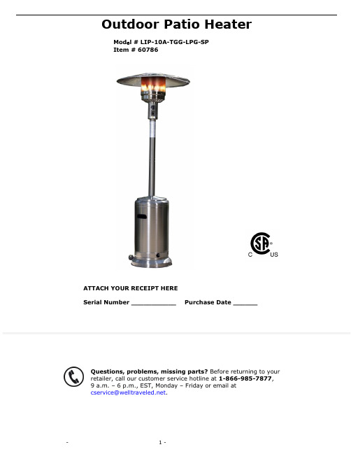
Outdoor Patio HeaterMod e l # LIP-10A-TGG-LPG-SP Item # 60786ATTACH YOUR RECEIPT HERESerial Number ___________ Purchase Date ______Questions, problems, missing parts? Before returning to your retailer, call our customer service hotline at 1-866-985-7877, 9 a.m. – 6 p.m., EST, Monday – Friday or email at *************************.SAFETY INFORMATIONSAFETY INFORMATIONPlease read and understand this entire manual before attempting to assemble, operate or install this appliance. If you have any questions regarding the product, please call customer service 1-866-985-7877, 9 a.m. –6 p.m., EST, Monday – Friday.This manual contains important information about the assembly, operation and maintenance of this patio heater. General safety information is presented in the first few pages and is also located throughout this manual. Keep this manual for future reference and to educate new users of this appliance. This manual should be read in conjunction with the labeling on the appliance. Safety precautions are essential when any mechanical or propane fueled equipment is involved. These precautions are necessary when using, storing, and servicing. Using this appliance with the respect and caution demanded will reduce the possibilities of personal injury or property damage. The following symbols shown below are used extensively throughout this manual. Always heed these precautions, as they are essential when using any mechanical or propane fueled equipment.PREPARATIONBefore beginning assembly of this appliance, make sure all parts are present. Compare all parts with package contents list and hardware contents as listed on pages 2 and 3 of this manual. If any part is missing or damaged, do not attempt to assemble this product. Contact customer service for replacement parts.ESTIMATED ASSEMBLY TIME: 60 minutesTools Required for Assembly (NOT included):Phillips screwdriver w/medium bladeLeak Detection SolutionAdjustable wrench (2) (Note: 10mm wrench or socket should fit M6 bolt; 13mm wrench or socket should fit M8 bolt.)ASSEMBLY1. Attach Wheel Assembly (K) to Base (J). Align holes in Wheel Assembly with corresponding holes in Base, and insert 2 M8x16 (AA) bolts through holesand finger tighten. Tighten with wrench once both bolts have been inserted. Hardware Used: 2 x AA, Bolt M8x162. Attach the Post Supports (I) to the Base (J). Align the holes in thebottom of each Post Support with the holes on the Base.Insert 1 M8x16 (AA) bolt through the hole in the support and into theBase and hand tighten. Repeat with the other 2 Post Supports andthen tighten all bolts with a wrench.Hardware Used: 3 x AA, Bolt M8x163.Attach the Lower Post (H) to the Post Supports (I). Once youhave tightened the bolts holding the Post Supports (I) to the Base (J),align the holes in the Lower Post (H) with the holes on the topsof the Post Supports (I) and insert a M6x35 (BB) bolt through a M6 (GG)washer and then through the hole in the Post Support. Affix anotherM6 (GG) washer onto the bottom of the M6x35 (BB) bolt and secure with aM6 (CC) nut. Repeat this in the 5 remaining holes (6 holes total—2 foreach Post Support piece). Hand tighten initially then tighten with awrench when all bolts have been inserted.Hardware Used: 6 x BB, Bolt M6x3512 x GG, Washer M66 x CC, Nut M61234. Attach Upper Post (F) to Lower Post (H) by screwing the two pieces of the posttogether.5. Place Tank Housing (D) onto Base (J). Slide Tank Housing (D) over the assembled Upper/Lower Post and down over the Post Supports. Rest Tank Housing on Base.6. Attach Head Assembly (C) to Upper Post (F).Note: There is a small piece of protective foam located in the neck of the Head Assembly that MUST be removed prior to attaching Head Assembly to the Upper Post.Route Gas Hose (E) down into Upper/Lower post assembly and align 4 small holes on Head Assembly with 4 Small holes in Upper Post(F).[HINT: Control knob should be above decal on post.]Insert 4 M6x10 (EE) bolts through 4 M6 lock washers into holes and tighten.Hardware Used : 4 x EE, Bolt M6x10 and Lock Washer M64 567. Panels (A) come packaged in two brown boxes with two panels in each box. Hardware for assembly is already affixed to each panel. Place two panels side by side and remove the two cap nuts and washers that are affixed to one panel. Insert the affixed bolts into the open holes on the adjacent panel. Place the washer over the bolt and screw on cap nut. Repeat these steps until all four panels are assembled. Then locate the Reflector Center Cap (B). You will need to remove the cap nuts and washers located at the top of each Reflector Panel to allow assembly of the Center Cap on each panel. Align the holes in the Center Cap with the bolts on each panel and affix washer and cap nut to complete assembly.8.assembled Hardware Used : 3 x DD, Wing Nut M89. Tank Housing.NOTE7 98A minimum supply pressure of .5 psi is required for the purpose of input adjustment of propane gas. Storage of an appliance indoors is permissible only if the cylinder is disconnected and removed from the appliance. A cylinder must be stored outdoors in a well-ventilated area out of the reach of children. A disconnected cylinder must have dust caps tightly installed and must not be stored in a building, garage, or any other enclosed area. The minimum permissible gas supply pressure of 11 W.C. is required for purpose of hose adjustment. The minimum hourly of 17,500 BTU is required input rating for a heater for automatic operation rating less than full input rating.The pressure regulator and hose assembly supplied with the appliance must be used.The installation must conform with local codes, or in the absence of local codes, with national fuel gas code, ANSI Z223.1/NFPA54, natural gas and propane Installation Code, CSA B149.1, or propane storage and handling code, B149.2A dented rusted or damaged propane cylinder may be hazardous and should be checked by your local cylinder supplier. Never use a propane cylinder with a damaged valve connection.The propane cylinder must be constructed and marked in accordance with the specifications for LP gas cylinders of the U.S. Department of Transportation (DOT) or the standard for cylinders, spheres and tubes for transportation of dangerous goods and commission, CAN/CSA-B339.The cylinder must have a listed overfilling prevention device.The cylinder must have a connection device compatible with the connection for the appliance.The cylinder used must include a collar to protect the cylinder valve.Never connect an unregulated propane cylinder to the heater.OPERATING INSTRUCTIONSLeak Check1. Make 2-3 oz. of leak check solution (one part liquid dishwashing detergent and three parts water).2. Apply several drops of solution where hose attaches to regulator.3. Apply several drops of solution where regulator connects to cylinder.4. Make sure all patio heater valves are OFF.5. Turn cylinder valve ON.IF BUBBLES APPEAR AT ANY CONNECTION, THERE IS A LEAK.1. Turn cylinder valve OFF.2. If leak is detected at hose/regulator connection, tighten connection and perform another leak test. If bubbles continue to appear, call our customer service hotline at 1-866-985-7877, 9 a.m. – 6 p.m., EST, Monday – Friday.check. If you continue to see bubbles after several attempts, cylinder valve is defective. Call our customer service hotline at 1-866-985-7877, 9 a.m. – 6 p.m., EST, Monday – FridayIF NO BUBBLES APPEAR AT ANY CONNECTION, THE CONNECTIONS ARE SECURE.Note: Whenever gas connections are loosened or removed, you must perform a complete leak check.Caution: Do not attempt to operate this appliance until you have read and understand all Safety Information in this manual and all assembly is complete and leak checks have been performed.Before Turning Gas Supply ON :1. Your heater was designed and approved for OUTDOOR use only. Do NOT use it inside a building, garage, or any other enclosed area.2. Make sure surrounding areas are free of combustible materials, gasoline, and other flammable vapors or liquids.3. Ensure that there is no obstruction to air ventilation. Be sure all gas connections are tight and there are no leaks.4. Be sure the cylinder cover is clear of debris. Be sure any component removed during assembly or servicing is replaced and fastened prior to starting.Before Lighting :1. Heater should be thoroughly inspected before each use, and by a qualified service person at least annually. If re-lighting a hot heater, always wait at least 5 minutes.2. Inspect the hose assembly for evidence of excessive abrasion, cuts, or wear. Suspected areas should be leak tested. If the hose leaks, it must be replaced prior to operation. Only use the replacement hose assembly specified by the manufacturer.Lighting :NOTE : For initial start or after any cylinder change, hold the control knob in for 2 minutes to purge air from all gas lines before proceeding.1. Turn the control knob to the “OFF” position.2. Fully open the LP cylinder valve.3. Turn the control knob half way between the small flame and the large flame symbols.4. Push control knob in and then push the RED igniter button to ignite the main burner. Repeat until the burner ignites. Keep the control knob fully pushed in for an additional 30 seconds after the burner ignites, then release the control knob.5. To increase the flame, turn the control knob clockwise toward the large flame symbol. To decrease the flame, turn the control know counter clockwise towards the small flame symbol.6. To turn the appliance OFF, push down the Control knob and turn clockwise to the OFF position.7. Wait at least 5 minutes before attempting to re-light the heater.8. Turn the gas cylinder valve to OFF or closed.If you experience any ignition problems, please consult “Troubleshooting” on page 13.Caution : Avoid inhaling fumes emitted from the heater’s first use. Smoke and odor from the burning of oils used in the manufacturing will appear. Both smoke and odor will dissipate after approximately 30 minutes. The heater should NOT produce thick black smoke.When Heater is ON:Emitter screen will become bright red due to intense heat. The color is more visible at night. Burner will display tongues of blue and yellow flame. These flames should not be yellow or produce thick black smoke, indicating an obstruction of airflow through the burners. The flame should be blue with straight yellow tops. If excessive yellow flame is detected, turn off heater and consult “Troubleshooting” on p age 13.Re-Lighting:Note: For your safety, control knob cannot be turned OFF without first depressing the control knob and then rotating to OFF.1. Turn control knob to OFF.2. Wait at least 5 minutes to allow gas to dissipate before re-lighting.3. Repe at the “Lighting” steps listed on page 10.Shut Down:1. Turn control knob clockwise to OFF while depressing the knob.(Normally, burner will make a slight popping noise when extinguished).2. Turn cylinder valve clockwise to OFF and disconnect regulator when heater is not in use.NOTE: After use, some discoloration of the emitter screen is normal.Operation Checklist:For a safe and pleasurable heating experience, perform this check before each use:Before Operating:1. I am familiar with entire ow ner’s manual and understand all precautions noted.2. All components are properly assembled, intact and operable.3. No alterations have been made.4. All gas connections are secure and do not leak.5. Wind velocity is below 10 mph.6. Unit will operate at reduced efficiency below 40 degrees F.7. Heater is for use outdoors (outside any enclosure).8. There is adequate fresh air ventilation.9. Heater is away from gasoline or other flammable liquids or vapors.10. Heater is away from windows, air intake openings, sprinklers and other water sources.11. Heater is at least 36 in. on top and at least 24 in. on sides from combustible materials.12. Heater is on a hard and level surface.13. There are no signs of spider or insect nests in heater orifices.14. All burner passages are clear.15. All air circulation passages are clear.16. Children and adults should be alerted to the hazards of high surface temperatures and should stay away to avoid burns or clothing ignition.17. Young children should be carefully supervised when they are in the area of the heater.18. Clothing or other protective material should not be hung from the heater, or placed on or near the heater.19. Any guard or other protective device removed for servicing the heater must be replaced prior to operating the heater.20. Installation and repair should be done by a qualified service person. The heater should be inspected before each use and at least annually by a qualified service person.21. More frequent cleaning may be required as necessary. It is imperative that control compartment burner and circulating air passageways of the heater be kept clean and free of debris and/or spider or insect nests.After Operation :1. Gas control knob is in OFF position.2. Gas tank valve is OFF.3. Disconnect gas line.To enjoy years of outstanding performance from your heater, make sure you perform the following maintenance activities on a regular basis:Keep exterior surfaces clean .1. Use soapy water for cleaning. Never use flammable or corrosive cleaning agents.2. While cleaning your unit, be sure to keep the area around the burner and control compartment dry at all times. Do not submerge the control valve assembly. If the gas control is submerged in water, do NOT use it. It must be replaced.3. Air flow must be unobstructed. Keep controls, burner, and circulating air passageways clean. Signs of possible blockage include:∙ Gas odor with extreme yellow tipping of flame. ∙ Heater does NOT reach the desired temperature. ∙ Heater glow is excessively uneven. ∙ Heater makes popping noise.∙ Spiders and insects can nest in burner or orifices. This dangerous condition can damage heater andrender it unsafe for use. Clean burner holes by using a heavy-duty pipe cleaner. Compressed air may help clear away smaller particles.∙ Carbon deposits may create a fire hazard. Clean dome and burner screen with warm soapy water if anycarbon deposits develop.Note : In a salt-air environment (such as near an ocean), corrosion occurs more quickly than normal. Frequently check for corroded areas and repair them promptly.TIP (FOR STAINLESS STEEL MODELS):Use high-quality automobile wax to help maintain the appearance of your heater. Apply to exterior surfaces from the post down. DO NOT apply to emitter screen or domes.Storage :Between uses:∙ Turn Control Knob OFF. ∙ Disconnect LP source.∙ Store heater upright in an area sheltered from direct contact with inclement weather (such as rain, sleet,hail, snow, dust and debris).∙ If desired, cover heater to protect exterior surfaces and to help prevent build-up in air passages. Neverleave LP cylinder exposed to direct sunlight or excessive heat.Note : Wait until heater is cool before covering .Service :Only a qualified service person should repair gas passages and associated components.Caution : Always allow heater to cool before attempting service.CARE AND MAINTENANCEIf you have any questions regarding this product, please call our customer service hotline at 1-866-985-7877, 9a.m. – 6 p.m. (EST), Monday – Friday, or email us at *************************.1 YEAR LIMITED WARRANTY – Customers in the Continental USAll components are warranted for a period of 1 year after date of purchase by the original owner against defects in materials and workmanship under normal use. This warranty does NOT cover normal wear and weathering, assembly and/or maintenance OR use in a commercial application if model is not designat ed as a commercial model. At Well Traveled Living’s sole discretion, products under warranty will be repaired and/or replaced at no charge to the customer. Any returns sent back to Well Traveled Living must be sent via prepaid freight and in the original retail packaging.For warranty service contact Well Traveled Living at the address, phone numbers or internet site and email listed in this owner’s manual. Be sure to have your sales receipt, date of purchase and catalogue/model numbers available when cal ling. All warranty service will be coordinated by the Well Traveled Living’s, Amelia Island, Florida service center.This warranty is extended only to the original purchaser. Proof of purchase will be required before warranty service is rendered. The sales receipt is the only valid proof of purchase. This warranty only covers failures due to defects in materials or workmanship which occur during normal use. Failures and/or damage which result from accident, negligence, misuse, abuse, neglect, mishandling, alteration or modification, failure to maintain, improper assembly or maintenance, service by unauthorized agency or use of unauthorized components or damage that is attributable to acts of God are NOT covered.***THERE ARE NO EXPRESS WARRANTIES EXCEPT AS LISTED ABOVE******PURCHASER ASSUMES ALL RISKS IN THE ASSEMBLY AND OPERATION OF THIS UNIT*** ***FAILURE TO FOLLOW WARNINGS AND OPERATIONAL INSTRUCTIONS CONTAINED IN THIS MANUAL CAN RESULT IN SEVERE PROPERTY DAMAGE AND/OR PERSONAL INJURY***IN NO EVENT WILL WELL TRAVELED LIVING, OR ITS DIRECTORS, OFFICERS OR AGENTS BE LIABLE TO THE PURCHASER OR ANY THIRD PARTY, WHETHER IN CONTRACT, IN TORT, OR ON ANY OTHER BASIS, FOR ANY INDIRECT, SPECIAL, PUNITIVE, EXEMPLARY, CONSEQUENTIAL, OR INCIDENTAL LOSS, COST, OR DAMAGE ARISING OUT OF OR IN CONNECTION WITH THE SALE, MAINTENANCE, USE, OR INABILITY TO USE THE PRODUCT, EVEN IF WELL TRAVELED LIVING OR ITS DIRECTORS, OFFICERS OR AGENTS HAVE BEEN ADVISED OF THE POSSIBILITY OF SUCH LOSSES, COSTS OR DAMAGES, OR IF SUCH LOSSES, COSTS, OR DAMAGES ARE FORESEEABLE. IN NO EVENT WILL WELL TRAVELED LIVING, OR ITS OFFICERS, DIRECTORS, OR AGENTS BE LIABLE FOR ANY DIRECT LOSSES, COSTS OR DAMAGES THAT EXCEED THE PURCHASE PRICE OF THE PRODUCT.SOME JURISDICTIONS DO NOT ALLOW THE EXCLUSION OR LIMITATION OF INCIDENTAL OR CONSEQUENTIAL DAMAGES, SO THE ABOVE LIMITATION OR EXCLUSION MAY NOT APPLY TO THE PURCHASER.This limited warranty gives you specific legal rights and you may also have other rights which vary from jurisdiction to jurisdiction. The provisions of the United Nations Convention on Contracts for the Sales of Goods shall not apply to this limited warranty or the sale of products covered by this limited warranty.***IMPORTANT NOTICE***-Do NOT r eturn to place of purchase-For customer service and warranty issuescontact our Customer Service Center at:(866)-985-7877 OREmail: *************************Customer Service Hours: Mon. – Fri. 9:00 a.m. – 6:00 p.m.(EST)Fire Sense®, Mojave Sun ®, and Well Traveled Living® are registered trademarks of Well Traveled Imports, Inc®. All assembly instruction presentations are the property of Well Traveled Imports, Inc.® and are protected by U.S. copyrightsand trademarks. All rights reserved.。
产品说明书(可印刷)
辅材消耗
由 于 模 块 面 均 热 在 由于水管内温度60℃,因此 电缆线温度在70℃以
4 0 ℃ 左 右 , 因 此 可 直 地面混凝土厚度在3cm以下 上,地面混凝土厚度
接 铺 设 地 面 材 料 , 会开裂,必须加装钢丝网, 至少5cm,并需加装
无 需 加 装 钢 丝 网 等 辅 至少增加25元/m2的间接成 钢丝网,至少增加30
智能•双控 环保•节能 养生•保健
1.2系统特性
碳晶地面采暖系统以其舒适性、经济性、安全性奉献社会广大用户。
在传统热对流循环采暖条件下,室内物体(地板、家具、
墙壁)的表面温度大约低于室内空气温度,所以这些物体
对人体、空气是冷辐射。
东灿碳晶地暖是以低温辐射为主的产品。
在低温辐射供暖的条件下,室内周围物体表面温度大约
产品绝缘强度高、阻燃、防水、防潮、耐腐蚀、免维修、使用寿命长。
智能•双控 环保•节能 养生•保健
1.1系统构成
东灿碳晶地暖系统由四大系统构成:发热系统,保温系统,控温系 统、电路系统。
(1) 发热系统:主要核心发热部件为碳晶发热板。 (2) 保温系统:主要材料为聚氨酯。保温系统的作用是杜绝碳晶板所 产生的热量向地坪方向的流失,并强制热量向室内传递。 (3) 控温系统:主要部件为电采暖温控器。温控器通过感应采暖室内 环境温度的变化,来控制碳晶板所提供的热量。合理的采暖温度的设定可 大大提高系统的有效工作效率,并减少能耗。 (4) 电路系统:由电源管线等安装辅材组成。
安装简便,盘线+温 控器。但必须做5公 分以上的水泥找平。 100m2需4人,2天安 装。
采暖效果
面状发热,预热时间 30~40分钟以内,同 时达到地面均热,冷 热点温差5℃左右。
暖风暖空间设备安装和使用手册说明书

Installation and operating manual ENCLOSURE HEATER TEF 9207 TUM7139 __________________________________________________________________________________Installlation ManualENCLOSURE HEATER TEF 9207Zone 1, Zone 2 & Safe AreaDocument properties (TUM7139)Revision Comment Revision date Approved- First issue - AKAA Removed EAC-certification 06.04.2022 CKRB Updated with new certificate and UKCA 01.04.2023 CKRInstallation and operating manualContentsDocument properties (TUM7139) (1)Warnings and risk levels (3)General information (3)Marking and intended use (4)Special conditions for safe use (5)Technical data (5)Product description (6)Transport and storage (6)Mounting and installation (7)Mounting (7)Electrical connections (8)Commissioning (9)Operation (9)Maintenance and cleaning (9)Disposal (10)Compliance/Conformity (10)R. Stahl Tranberg declaration of Conformity: (11)Warnings and risk levelsDANGERNon-compliance with the instruction results in risk of severe or fatal injuries to personsWARNINGNon-compliance with the instruction may result in risk of severe or fatal injuries to personsCAUTIONNon-compliance with the instruction may result in risk of injuries or damage to equipmentNOTICENon-compliance with the instruction may result in reduced lifetime of equipment, malfunctions etc.General informationBefore installation, make sure to read and understand this installation and operating manual.Observe national assembly and installation regulations.Always contact the manufacturer if anything is unclear, or if you notice any faults on the product or in this document.This installation and operating manual shall be available to anyone operating, installing, inspecting, modifying or repairing the equipment.For further information, see the referenced certificates.Marking and intended useDANGERNot for use in Zone 0 or Class I division 1.CAUTIONThe enclosure heater shall not be exposed to direct sunlight, dust, water or similar. The enclosure heater should be protected from contamination and shall not be cleaned with running water.•CE•ATEX / IECEx/ UKEx: II 2G Ex 60079-30-1 IIC T3 GbI 2G Ex 60079-30-1 eb mb IIC T3 GbFor use in hazardous areas Zone 1 or Zone 2For use in onshore/offshore areas protected from exposure.Special conditions for safe useDANGERSpecial conditions for safe use are critical conditions to maintain the explosion protection of the equipment. These shall be adhered to in all cases and under all circumstances.•When the heater is not installed inside a certified hazardous area enclosure (for example Ex p, Ex e, Exd etc.) the flying lead cable shall be protected from mechanical damage.•The heaters with thermostat shall be connected to a circuit breaker with rated current max. 16A and a breaking capacity of min. 1500A.•The supply circuit shall include an electrical protection device in conformity with EN 60079-30-1 (For version 2015/2017 clause 4.3).•Follow the instructions given in this IOMTechnical dataProperty Value ValueExplosion protection* Note:”mb” only with thermostat II 2G Ex 60079-30-1 IIC T3 Gb II 2G Ex 60079-30-1 eb mb IICT3 Gb *Input voltage and frequency 220-240V AC (model dependant) 50/60HzInput current Model specific Start-up: >6x nominal current Rated power 100-1000W (model dependent)Ingress protection IP66Ambient temperature -50°C …+50°C (+80°C if thermostat is used or power is disconnected) For use in zone Zone 1 or 2Communication N/AWeight Model specific, see datasheetSize Model specific, see datasheet Mounting: 4x M6 Screw Terminals Screw terminals, 6(10)mm²Entries/Cable glands If installed, M25 (CMP A2F 25) Ø11.1-20.0mmHousing material Stainless steelOther materials Polymer, Silicone, BrassProduct descriptionThe TEF 9207 Enclosure heater consists of a self-limiting heat tracing cable arranged in stainless steel housing. Different versions come with a flying lead silicone cable, integrated junction box or integrated junction box with thermostat. The product series is designed to maintain a minimum temperature inside an enclosure (distribution board, storage cabinet or similar). The self-limiting characteristic of the heating element prevents severe over-heating, but a thermostat is always recommended, especially for sensitive equipment.Transport and storage•Transport and store the equipment only in the original packaging•Store the equipment in a dry and vibration free place•Do not drop!•Protect the flying lead cable during transport and storageMounting and installationDANGERIncorrect mounting and installation may lead to ignition of an explosive atmosphere, risk of falling objects, risk for electric shock and risk for equipment malfunction. In turn, this can lead to severe damage and/or injuries. The integrated silicone cable is susceptible to mechanical damage and shall be protected in all phases (transport, storage, installation and operation). Observe “Special conditions for safe use”.MountingThe TEF 9207 enclosure heater shall be mounted on a flat and sturdy surface. Mounting is done with 4x M6 screws. The mounting shall be done to ensure that any foreseen load, vibrations, shock or similar do not impose a risk of mechanical failure or loosening of screws.For detailed mounting dimensions, see the respective datasheet for each model and type. Mounting dimensionsBody size E FA 190 160B 440 200C 590 240D 760 320 Sandwich heaters D 760 397Installation and operating manual ENCLOSURE HEATER TEF 9207 TUM7139 __________________________________________________________________________________ Electrical connectionsNOTICESee “Special conditions for safe use”Electrical connections shall only be performed by trained personnel according to the relevant regulations. Special care shall be taken to ensure proper connection of the wires. The insulation shall reach all the way to the connection point, and no strands shall be loose. Ferrules are recommended.The supply circuit shall be protected according to EN/IEC 60079-30-1. The flying lead cable shall be terminated in a manner suitable for the hazardous area classification (e.g. in an Ex e junction box).Power terminals are 6mm², and the PE terminal is 10mm² max. Min. 2,5mm² cables are recommended. Enclosure heaters with a junction box are delivered with 1 pc. cable gland for cables Ø11.1-20mm.CommissioningDuring commissioning, an insulation resistance test of max 2550V DC is recommended. For critical applications, a thermostat function test is recommended. Verification of temperatures inside enclosures is strongly recommended.OperationTo save energy, ensure a long lifetime of the enclosure heaters, and to prevent over-heating of enclosures and components, the heater should be switched off when heating is not needed. This could be done with a thermostat, manually or based on seasonal variations.Regular visual inspections, earth-fault- or insulation resistance measurements shall be performed. Inspections shall be carried out according to IEC/EN 60079-17 or other relevant standards.Maintenance and cleaningAs stated above, regular inspections and maintenance shall be performed according to IEC/EN 60079-17 or equivalent.Clean only with a damp cloth, and mild detergents. Do not use running water. Avoid chemicals with high or low pH, abrasives, high pressure washer, strong detergents, solvents, petroleum- or alcohol based cleaning agents and similar. Avoid any corrosive media.DisposalCAUTIONThis equipment or part of this equipment is considered EE-Waste, and shall be handled accordingly •Observe national and local regulations and statutory regulations regarding disposal•Separate materials when sending it for recycling•Ensure environmentally friendly disposal of all components•No component or packaging shall end up in the ocean during any stage of the product’s lifetimeCompliance/Conformity•ATEX: CML 22 ATEX 3623X•UKEX: CML 22 UKEX 3624X•IECEx: IECEx CML 22.0096XThe certificates are issued in based on the following standards:ATEX / UKEX: IECEx:EN IEC 60079-0:2018 IEC 60079-0:2017 Ed. 7.0EN IEC 60079-7:2015/A1:2018 IEC 60079-7:2017 Ed. 5.1EN 60079-18:2015/A1:2017 IEC 60079-18:2017 Ed. 4.1EN 60079-30-1:2017 IEC/IEEE 60079-30-1:2015 Ed. 1.0Installation and operating manual ENCLOSURE HEATER TEF 9207 TUM7139 __________________________________________________________________________________R. Stahl Tranberg declaration of Conformity:EU DoC: Document no. TDC3359Installation and operating manual ENCLOSURE HEATER TEF 9207 TUM7139 __________________________________________________________________________________UK DoC: Document no. TDC7382。
取暖器说明书.pdf_1699314728.2489011

INSTALLATION INSTRUCTIONS AND USER GUIDEPH PlusSMART PANEL CONVECTOR HEATERPH-075 PlusPH-125 PlusPH-150 PlusPH-200 Plus Please read these instructions before installing or using this appliance for the first time. These instructions must be followed for the safe installation of the radiator. Any1.- WARNING Please read these instructions before installing or using this appliance for the first time.•The warranty of the heater will not cover any damage caused by non-observance of any of these instructions.•The instructions should be retained for future reference. This guide must be kept and given to any new owner.•This appliance can be used by children aged from 8 years and above and persons with reduced physical, sensory or mental capabilities or lack of experience and knowledge if they have been given supervision or instruction concerning the use of the appliance in a safe way and understand the hazards involved. Children must not play with the appliance. Cleaning and user maintenance must not be made by children withoutsupervision.•Children aged from 3 years and less than 8 years shall only switch on/off the appliance provided that it has been placed or installed in its intended normal operating position and they have been given supervision or instruction concerning use of the appliance in a safe way and understand the hazards involved. Children aged from 3 years and less than 8 years shall not plug in, regulate and clean the appliance or perform usermaintenance.•Children of less than 3 years should be kept away unless continuously supervised.•Please check that the voltage in the rating label fits the power supply.•The use of panel heaters is forbidden in any area where there is a presence of gases, explosives or inflammable objects.•Do not use this heater to dry clothes. Do not cover this heater or put objects in contact with it.•Neither the connecting cable nor any other object must come into contact with the hot unit.•Do not cover this heater at any time.•The air outlet at the top of the thermal radiator and the air inlet at the bottom are provided to ensure the most efficient operation of the appliance. They also protect the heater from overheating; therefore, it isessential that at no time are they covered.•This heater should be switched off at the isolating switch before any repair work is carried out.•The installation must be carried out in accordance with the current electrical regulations.•Should the heater be moved and reinstalled it is essential that the work is carried out by a fully qualified technician.•The heater should not be installed just below an electrical socket.•The appliance must be installed in such a way that it is impossible for anyone using a bath or shower, to touch the controls.•The heater is fitted with a flexible cable size 3 x 1.00 mm² for electrical connection. It may be used to connect the heater to the fixed wiring of the premised through a suitable connection box positionedadjacent to the heater.•This appliance must be connected to the supply by fixed wiring. The supply circuit to the heater must incorporate a double pole isolating switch having a contact separation of at least 3 mm.•If the flexible power cable for this unit is damaged, it may only be replaced by a repair workshop recognised by the manufacturer, as special tools are necessary.•This appliance must be earthed.•All models are supplied with an electrical interrupt cut-out. This will switch off the heater if, for any reason, it overheats. Should the cut-out operate, turn the heater off and remove the cause for the overheating. The cut-out will be reset automatically.•Please, if included, complete the enclosed warranty card and return it to the manufacturer to enable registration to take place.•The presence of air particles of smoke, dust and other pollutants could, in time, discolour the walls and surfaces around the heater.•CAUTION — Some parts of this product can become very hot and cause burns. Particular attention must be given when children and vulnerable people are present.••WARNING: In order to avoid overheating do not cover the heater.•41.0 cm ( 750W)56.0 cm (1250W)63.5 cm (1500W)78.5 cm (2000W)min 15cm min 15cmm i n 20c mm i n 20c m41.0 c m8cm 10cm2.- INSTALLATION INSTRUCTIONS- Open the package and check that it is the correct model and it is in good condition.- To obtain optimum performances it is necessary to maintain a minimum clearance of 50 cm between the panel heater and any inflammable material as furniture, curtains etc.- The studs and screws to attach the supports are in the accessories bag.- Fix the two square brackets to the back of the heater by using the two smalls screws. (see Fig.1)- Position and fix the top bracket at the correct distance from the floor (see Fig.2) and hang the unit on the hooks of the top bracket.- Mark the fixing points on the wall using a pencil. Use the heater fixing holes as a template and mark the wall through the two fixing holes in the square brackets. Fix the heater to the wall.3.- USING THE PANEL HEATERDIGITAL CONTROL WITH DAILY AND WEEKLY PROGRAMMINGMain switch :All models are equipped with one switch on the right surface allowing the panelheater disconnection.Ph Plus panel heaters have built in an electronic thermostat with a sensibility of 0.1 ºC. It is possible to set temperatures with an accuracy of 0.5ºC.The daily or weekly programmer (selectable) allows you to allocate three different temperature levels to any of the 48 intervals of 30 minutes of the day.Digital DISPLAY:It shows the time, temperature and other messages.Frost protection key:If the display shows the time the heater is in frost protection mode. Press this key to shift from frost protection mode to standard mode and vice versa.Heating indicator:This small dot will be lit when the heater is consuming energy. SUN indicator Press this key for more than two seconds to set the time or day of the week. PRG key:Allows you to create check or modify programs.Move forward with + or – keys and allocate the SUN, MOON, or temperature to any of the 48 intervals of 30 minutes of the day by means of the relevant key.Key “+”:It increases the values. SUN key: Press once to see the SUN temperature value. Press + or – keys to modify the value. MOON key: Press once to see the MOON temperature value. Press + or – keys to modify the value. MOON indicator Key “-”:It decreases the values.SWITCHING ON THE PANEL HEATEROnce the heater is connected to a main supply, switch on the heater by setting the switch marked I-O positioned at the rigth side of the panel heater to “I”. The off position is marked “O”.SETTING THE TIMEPress the key more than two seconds. The display will show the time intermittently. Set the hours by pressing + and -keys and press the . Set the minutes the same way. Press once more the key to store the time. If at any time it is necessary to set the time press the key and repeat the above steps.FROST PROTECTION MODE ❆With this mode on, if the room temperature drops below 3ºC the heater will connect itself automatically.If the display shows the time the panel heater is in frost protection mode. Press the ❆ key to shift from frost protection mode (time is shown in the display) to standard mode (temperature is shown in the display) and vice versa.PROGRAMMING THE PANEL HEATERThe panel heater operates in programming mode maintaining the SUN, MOON or ❆temperatures as per the introduced program. If the display shows the time, the panel heater is in frost protection mode.SUN, MOON AND ❆ TEMPERATURESThe electronic programmer is able to handle three temperature levels during the 24h of the day.Press the key to set the SUN temperature. The display will show the SUN temperature value blinking.Set the SUN temperature value by means of the + o –keys and press the key to store the value. If the display shows the time the heater is in frost protection mode. Press the ❆key to shift from frost protection mode (time is shown in the display) to standard mode (temperature is shown in the display) and vice versa.Repeat the above steps with the key to set the MOON temperature.The ❆ temperature level is 3ºC and it is a fix value. This temperature level can be used as off selection when setting the temperatures during curtain times of the day.SUN, MOON, or ❆ temperatures can be allocated to any of the 48 intervals of 30 minutes of the day.DAILY PROGRAMMESIt is basic to visualize the day split into 48 intervals of 30 minutes each; SUN, MOON, or ❆ temperatures can be allocated to any of them.The default settings include daily mode so that the heater will repeat the program every day. If different programmes are required along a week, please see the next step WEEKLY PROGRAMMES. To check a programme or to make a new one, follow these steps:Press the PRG00:00 intermittently. Press one of the three keys ❆ to allocate SUN, indicator will be lit. If OFF temperature ❆is selected both luminous indicators will be off.Press the + key to go to the next interval. The display will show 00:30 intermittently and, again, press one of the three keys ❆ to allocate SUN, MOON or OFF (frost protection) from 00:30h to 01:00h or press + key directly if the existing temperature level is ok.Repeat these steps allocating the desired temperatures levels over the 24 hours of the day. Press the – key at any time to modify a previous period. By reaching the 23:30 in the display and pressing + key, the controller will store the program and will return to the previous mode.At any time PRG key can be used also to store the program and return the previous mode.1 - Press PRG 00:002 - Press ❆ Off3 - Press + key00:304 - Repeat steps 2 and 3 until display shows: 07:305 - PressOn6 - Press + key 08:007 - Press8 - Press + key 08:309 - Press10 - Press + key 09:0011 - Press12 - Press + key09:30 13 - Repeat steps 11 and 12 until display shows: 13:0014 - Press15 - Press + key13:30 16 - Repeat steps 14 and 15 until display shows: 15:0017 - Press18 - Press + key15:30 19 - Repeat steps 17 and 18 until display shows: 19:3020 - Press21 - Press + key20:00 22 - Repeat steps 20 and 21 until display shows: 23:3023 - Press24 - Press + keyGRAB00:0001:0002:0003:0004:0005:0006:0007:0008:0009:0010:0011:0012:0013:0014:0015:0016:0017:0018:0019:0020:0021:0022:0023:0024:00❆SUNMOONOFFEXAMPLELet’s see an example of how to introduce a program with the above distribution of temperatures.OFF from 24:00h to 7:30h in the morning. The heater will be on only if the temperature drops to 3ºC.SUN temperature from 7:30h to 9:00h.MOON temperature from 9:00h to 13:00h.SUN temperature from 13:00h to 15:00h.MOON temperature from 15:00h to 19:30h.SUN temperature from 19:30h to 24:00h.WEEKLY PROGRAMMESIt is possible to allocate different programs to different days of the week. To do this, the controller has to be upgrade from 24hr mode (factory default) to 24hr/7days mode as follows:Switch off the panel heater by turning off the main switch at the right side of the heater, the display will be Off. Press the key and at the same time turn on the main switch maintaining the key at least five seconds. The display will show P-SE which means that weekly mode has been set.SETTING THE DAY: Press the key more than two seconds and the display will show the number of the day. Set the correct number, if required, by pressing + or – keys. Press the key and the display will show now the time. Press again the key and new values will be stored.To check a programme or to make a new one press PRG key: The display will show dia1. Press again PRG key and the display will show 00:00intermittently. Follow now the steps from DAILY PROGRAMMES section until the display shows again dia1. Repeat this process with the 7 days of the week. When the display shows dia7 the weekly program will be stored by pressing + key.If the display shows dia1 then, pressing + key more than three seconds will copy the day 1 program to day 2 and so on.It is possible to allocate any of the three temperature levels to all the intervals of any day maintaining the relevant ❆ key until an audible signal is heard.To turn back a controller from 24hr/7days to a single 24hr press PRG key more than six seconds. This will restore the factory default settings.KEYBOARD LOCKPress the ❆will keep on working internally. To unlock the keyboard, press again the ❆ key more than six seconds.SUN MANUAL OVERRIDEMaintain the SUN Key pressed for 4 seconds to set the Sun Manual Override. The heater will maintain the sun temperature set point and will ignore the pre-set program until the next change in programming temperature level.Both luminous indicators SUN and MOON will be lit. This function could be useful when SUN temperature is required and we do not want to modify the program.By pressing the SUN key for 4 seconds with Sun Manual Override activated, the function will be removed and the heater will follow the programme again.4.- ADVANCED FUNCTIONOPEN WINDOW DETECTIONWith open window detection activated, the heating element will be disconnected automatically when a sharp decrease in temperature in the room is detected avoiding energy wastage. After this period of time, the panel heater returns to the prior operation mode.When Open Window Detection is working, the word Open will be displayed alternating with the status of the current mode. Note: To activate the open window detection please refer to ADVANCED FUNCTION ACTIVATION section.ADAPTIVE START CONTROLPH Plus electronic control analyses the heating requirements of the room where the panel heater is installed using this information to turn on the heating element in advance in order to reach the set point temperature at the desired time.When Adaptive Start Control is working, the word AdAP will be displayed alternating with the status of the current mode. Note: To activate the adaptive start control please refer to ADVANCED FUNCTION ACTIVATION section.ADVANCED FUNCTION ACTIVATIONAdvanced functions Open Windows Detection and Adaptive Start Control are disabled by default. To enable / disable these functions, the following steps must be followed:Switch off the panel heater by turning off the main switch at the right side of the heater, the display will be Off. Press the ❆ key and at the same time turn on the main switch maintaining the ❆ key at least five seconds.alternating with the status of the function (On or OFF). Use the navigation keys + or – to enable /Confirm the new value for the function by pressing the PRG key. The next function (AdAP) is shown alternating with its status (On or OFF). Use the navigation keys + or – to enable / disable Adaptive Start Control function. Confirm the new value for the function by pressing the PRG key.5.- UNIT RESETThe panel heater reset establishes the factory configuration of the heater removing the programming, establishing the dailyPRG key for 4 seconds, the display will show6.- CLEANING AND MAINTENANCEThe panel heaters do not precise any special maintenance providing thermal comfort during large periods. Clean dust with a dry, soft cloth only when the unit is disconnected and cold.Do not use solvents or abrasive products for cleaning.This panel heater has been manufactured under an assured quality system using environment friendly processes.Please take the panel heaters to a clean point once their useful life is finished, in order to recycle their materials in the right way.7.- TROUBLESHOOTING8.- SPECIFICATIONS9.- MAIN COMPONENTS LISTMain PCB ref. 30100084 750 W Heating Element ref. 40491755 Keyboard ref. 40491702 1250 W Heating Element ref. 40491757 85ºC thermal limiter ref. 30100040 1500 W Heating Element ref. 40491759 Main Switch ref. 46100530 2000 W Heating Element ref. 40491761EN10.- WIRING11.- PRODUCT FICHEErPCommission Regulation (UE) 2015/1188 of 28 April 2015. Ecodesign requirements for electric fixed local space heater.10Supplier:ELNUR UK Ltd.Unit I, Brown Street North Leigh, Lancashire. WN7 1 BU Telephone +44(0)1942 670119 *************.ukManufactured by:ELNUR S.A.Travesía de Villa Esther, 11 28110 Algete - Madrid Telephone +34 91 628 1440As a part of the policy of continuous product improvement, Elnur s.a. reserves the right to alter specifications without notice.40491700 R1The symbol on the product or in its packaging indicates that this product may not be treated as household waste. Instead it shall be handed over to the applicable collection point for the recycling of electrical and electronic equipment. By ensuring this product is disposed of correctly, you will help prevent potential negative consequences for the environment and human health, which could otherwise be caused by inappropriate waste handling of this product. For more detailed information about recycling of this product, please contact your local city office, your household waste disposal service or the shop where you purchased the product. These instructions are only valid in the EU member states.。
现浇轻质保温复合墙体应用手册.
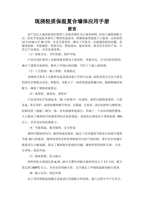
现浇轻质保温复合墙体应用手册前言本产品以大量的铁尾矿粉等工业废弃物作为主要原材料,经加入独特的配方后,用化学发泡技术替代了物理发泡技术,使墙体成型速度大大提高,由原来的24小时减少至20分钟,并且无需养护,解决了环保及二次能源消耗的问题。
是建筑创新、节能减排、变废为宝、降低成本、提高效率、惠及民生的好产品,与其它产品相比,具有显著优势:(1)变废为宝,节约资源,保护环境。
产品以尾矿粉等工业固体废弃物为主要原料,变废为宝,并可回收再利用,减少了建筑垃圾排放,解决了环境污染问题,节约了大量土地资源。
(2)工艺简便,施工智能,质量稳定该墙体只需木工支模和设备浇筑两道工序即可完成,浇筑采用公司自主研发的国内首例集自动化、智能化、多配方于一体的智能连续灌注机,能够精确控制配方,确保了墙体质量稳定。
(3)成型快、强度高、韧性好产品采用化学发泡技术,20分钟便可一次成型,成型后凝固速度快,只需常温、常压养护。
成型的墙体横平竖直,无裂缝,无变形,浇注的材料与钢骨架、轻钢龙骨(箱板)凝为一体,没有接缝和连接点,形成了一个良好的刚性整体,大大提高了墙体的空间强度和抗压抗折强度,表面抗压强度高于国家标准50%以上,具有良好的抗震能力。
(4)节能保温,隔音隔热,安全舒适墙体空隙致密均匀,隔热保温性能好,超过了民用建筑节能设计标准中建筑节能65%的要求;墙体材质的多样性和细密均匀的气泡结构,使声音在传播中能量发生大幅衰减,保证了墙体隔音性能的卓越;墙体所使用材料无毒、无害、无异味,绿色环保。
(5)墙体阻燃,防火耐火材料的防火级别达到A级,耐火完整性和耐火隔热性均大于3.5小时,耐火度达到1000°C以上,具有良好的耐火性,完全满足了外墙保温板的耐火要求。
(6)施工洁净、绿色环保由于采用智能连续灌注设备进行直接配方和浇筑,施工过程中不产生灰尘、废气、废水和废渣,实现了洁净施工。
(7)防腐、防渗、防脱落墙体为一体式刚性结构,无裂缝,整体性好,墙体芯材配方中加有防腐成分,使墙体可有效解决渗水、霉变、回潮、风化脱落、梁(柱)脱离等后顾之忧。
采暖说明书
目录第一章工程概况 (2)1.1建筑概况 (2)1.2设计依据 (2)1.3设计内容 (2)1.4气象条件 (3)1.5围护结构特点 (3)第二章供暖热负荷的计算 (4)2.1房间围护结构传热耗热量的计算 (4)2.1.1 围护结构耗热量计算公式 (4)2.2围护结构的附加耗热量的计算 (4)2.2.1 朝向修正 ................................................................................................... ..42.2.2 风力附加 (4)2.2.3 高度附加 (4)2.3门窗缝隙渗入冷空气的耗热量 (5)2.3.1 渗入冷空气耗热量计算公式 (5)2.4其他楼层房间的采暖热负荷集总 (5)第三章散热器的选择计算 (9)3.1散热器的相关参数 (9)3.1.1 散热器选型及安装形式 (9)3.1.2 注意事项 (9)3.2散热器的选择计算 (9)3.2.1 散热器面积计算公式 (9)3.2.2 散热器传热系数计算公式 (10)3.3其他楼层各房间内部散热器的选择 (10)第四章水力计算 (10)4.1相关参数的设置 (11)4.2水力计算 (11)4.2.1 水力计算公式 (12)4.3各管段的水力计算 (12)4.4各立管的水力计算 (12)总结及致谢 (13)参考文献 (13)第一章工程概况1.1建筑概况此次设计为沈阳市实验附小综合楼,建筑面积4574.2㎡,建筑高度21.55m,五层建筑,全为地上建筑。
其中1-4层为教室、活动室、休息室、会议室等层高为4.2m,5层为水箱间。
建筑耐久年限50年,6度防震烈度。
1.2设计依据(1)《民用建筑供暖通风与空气调节设计规范》GB50736——2012(2)《实用供热空调设计手册》(3)设计任务书(4)建筑设计方提供的建筑平面图1.3设计内容1.3.1 设计项目的要求在达到采暖要求的同时,设计图也要达到施工图要求,方案合理,系统清楚,画面清晰。
- 1、下载文档前请自行甄别文档内容的完整性,平台不提供额外的编辑、内容补充、找答案等附加服务。
- 2、"仅部分预览"的文档,不可在线预览部分如存在完整性等问题,可反馈申请退款(可完整预览的文档不适用该条件!)。
- 3、如文档侵犯您的权益,请联系客服反馈,我们会尽快为您处理(人工客服工作时间:9:00-18:30)。
温馨提示
感谢阁下购买建通牌远红外碳晶辐射电暖器,以下将对本产品详细介绍与使用操作说明为使您更好使用本产品,安装使用前请详细阅读说明书,以免产生安装使用不当而引起严重后果,若违反本使用规定,建通公司概不负责,请同时将本说明书保存好,以备日后使用。
机器如果出现故障,请勿自行打开修理,否则发生的一切后果建通公司概不负责。
安全注意事项
使用前需先检查所有电压是否与本机电压标签上之标示相符,拔出插头前先关掉电源,勿用湿手拔电源插头。
使用前先检查电源线以及插头有否破损,电源线请勿曲折,拉扯。
请勿用利器破坏碳晶发热板表面,以免损坏其碳晶电热板周边电极,造成碳晶发热板不制热。
长时间不用或离开,请关闭电源或断电。
电压在220V10%内波动不会影响本产品的使用。
保养与储藏
辐射采暖器不得直接置于电源插座正下方;
避免靠近窗帘或其他可燃、易燃材料安装,否则可能存在火灾危险;
辐射器表面严禁覆盖其他任何物体;
勿在无人看护的小孩,行动不便的老人,意识精神不正常的人的场合使用,以免事故的发生。
维修和更换机内电热元件及温控器等,应由专业电工完成。
公司简介
中国昆山建通科技有限公司,是一家致力于碳
素发热材料的研发、应用和生产的信誉公司。
和国内多家高等院校保持长久合作关系,始终站在科技的前沿,奠定行业领导品牌地位。
公司已成功通过ISO9001质量管理体系认证,GMC环球市场“中国优质制造商”认证,中国CCTV 上榜品牌,中国绿色、健康,节能、环保产品。
产品介绍
建通碳晶电暖器,是建通科技有限公司多年来科研的结晶,克服了电热管电暖器、空调、暖风机、油汀等各类采暖器的缺点,具有大面积均匀发热,通过热辐射方式安静送暖,安全性高、省电方便,实用美观的特点,自2007年开发以来,已成功解决了没有取暖设施的千家万户的取暖难题,深受广大消费者好评和信赖,产品远销韩国、日本等国家。
主要功能和特点
1、大面积均匀供热,温度均匀
2、无金属电器,防水绝缘性能好,安全可靠,居浴两用。
3、辐射采暖器的热能以红外线电热波形式传播,热效率高。
这种辐射式供热,空气不对流,从而使空气新鲜而清洁,热量分布均匀,让使用者感觉自然、清新、舒适,如沐阳光般的温暖。
4、外形美观,体轻耐用,可单品摆放,也可多个组合,款式、规格自由选定。
5、 本品与温控器配套使用,可有效控制室内温度,打到节能目的。
电暖器工作原理
电暖器由碳晶发热板、耐高温PVC外框,挂件,安全系统,防水系统、聚胺酯环保保温材料,电源线等构成,发热体发出热量后,经对流传热均匀安静的将热量传到室内,达到取暖目的。
零部件说明
使用说明
正常使用条件:
环境温度:±30℃
额定工作电压:220V AC
额定频率:50Hz
设计选用要点
适用范围
民用住宅、工厂、商场、超市、学校、部队、医院、邮局、银行、体育场馆、其他公共场所等各类建筑用采暖。
辐射采暖器参数
型号
功率1000W 300w、400w、500w
规格1000*600 500*900 750*600
高度mm 65 65 65 65 65 65 65 65
产品参数
额定电压~ 220V、50Hz
耐压强度3750V
漏电电流≤0.24mA 表面工作温度35℃±5
工作相对湿度≯95%
使用环境温度-40℃~120℃
三包凭证
客户姓名地址
电话邮政编
码
购买日期购买方
式经销商电话
型号产品条
码
包修期
维修记录
接机日期维修
日期
故障与
措施
维
修
部
维
修
员
维修
费
配件
费
退换货
证明。