TMH-QPSR 2-31997 1
PrimeDirect Probe RT-qPCR Mix产品说明书

URL:
3
PrimeDirect™ Probe RT-qPCR Mix
mRNA
cDNA 3’
Specific primer (forward) 5’
3’
5’ 3’ 5’ 3’ 5’ 3’
Cat. #RR650A
v201906Da
3’
5’
Specific primer (reverse)
IV. Materials Required but not Provided
2
URL:
PrimeDirect™ Probe RT-qPCR Mix
Cat. #RR650A
v201906Da
I. Description
PrimeDirect Probe RT-qPCR Mix is designed for one-step real-time RT-PCR via probe detection (5'-nuclease method). This product is supplied as a 2X premix to facilitate easy preparation of reaction mixtures, requiring only the addition of your primer, probe, and sample. The RT-qPCR can be performed by simply adding your sample directly to the reaction mixture without intervening nucleic acid purification steps. The protocol for performing all steps in a single tube, from extraction of the nucleic acid to reverse transcription and qPCR, greatly reduces hands-on time and risk of contamination. The continuous reaction from nucleic acid extraction (90℃) through reverse transcription (55 to 65℃) is also suitable for the detection of RNA viruses with complex higher-order structures. High-efficiency PCR after cDNA synthesis detects DNA amplification in real time by increasing fluorescence from the probe. Because this product is highly resistant to various PCR inhibitory substances such as heparin (blood) and humic acid (soil), it can be used to directly detect viruses and bacteria in various biological specimens and to directly analyze gene expression in cells.
ICP DAS I-7017R 8-ch Voltage and Current Input DAQ

I-7017R - 8-ch Voltage and Current Input DAQ Module - QuickStart (May/2020)ICP DAS USA, Inc. | | 1-310-517-9888 | 24309 Narbonne Ave. Suite 200. Lomita, CA 90717I-7017R8 Channels Voltage & Current InputData Acquisition ModuleQuick Start GuideProduct Website:https:///i_7017_r.html/dcon_utility_pro.htmlIntroductionThe I-7017R is an 8-channel analog input module with an extremely high quality protection mechanism where the overvoltage protection is 240 Vrms. The input type includes both voltage and current. The sampling rate of the I-7017R is adjustable, meaning that either fast mode or normal mode can be selected. The I-7017R also has 4 kV ESD protection as well as 3000 VDC intra-module isolation. The I-7017R-A5 is an 8-channel analog input module that is especially designed for high voltage input, and has an input range of between -50 V ~ +50 V or -150 V ~ +150 V.Packing ListI-7017RPlastic RailCDQuick Start GuideI-7017R - 8-ch Voltage and Current Input DAQ Module - QuickStart (May/2020)ICP DAS USA, Inc. | | 1-310-517-9888 | 24309 Narbonne Ave. Suite 200. Lomita, CA 90717⏹Internal I/O Structure < I-7017R >⏹Pin Assignments < I-7017R, I-7017R >⏹Internal I/O Structure (I-7017R)⏹Modbus Table (M-7017R only)Address Description R/W 10129 ~Over/under range status of channel 0R 10136to 7 for 4 ~ 20mA or 0 ~ 20mA ranges 00129 ~0013630001 ~Analog input value of channel 0 to 7R 3000840001 ~4000840481Firmware version (low word)R 40482Firmware version (high word)R 40483Module name (low word)R 40484Module name (high word)R 40485Module address, valid range: 1 ~ 247R/W 40486Bits 5:0R/WBaud rate, 0x03 ~ 0x0ACode0x030x040x050x06Baud1200240048009600Code0x070x080x090x0ABaud192003840057600115200Bits 7:600: no parity, 1 stop bit01: no parity, 2 stop bit10: even parity, 1 stop bit11: odd parity, 1 stop bit40487Type code R/W Address Description R/W 40488Modbus response delay time in ms,R/W valid range: 0 ~ 3040489Host watchdog timeout value, 0 ~R/W 255, in 0.1s40490Channel enable/disable, 00h ~ FFh R/W 40492Host watchdog timeout count, write 0R/W to clear00257Protocol, 0: DCON, 1: Modbus RTU R/W 00259Filter setting, 0: 60Hz rejection, 1:R/W 50Hz rejection002611: enable, 0: disable host watchdog R/W 00269Modbus data format, 0: hex, 1:R/W engineering00270Host watch dog timeout status, write R/W1 to clear host watch dog timeoutstatus002711: enable, 0: disable fast mode R/W 00273Reset status, 1: first read after R powered on, 0: not the first read afterpowered on⏹DCON ProtocolFunctions Command Response NotesRead module name$AAM!AA(Data)AA: address number Read module firmware version$AAF!AA(Data)Read all analog input data#aa>(data)Read analog input data of each channel (<=16 channel)#aai>(data)i: channel number (Hex) Read analog input data of each channel (>16 channel)#aaii>(data)ii: channel number (Hex) If you want to know the detail DCON protocol, please check it from CD or webCD path: \\napdos\7000\manual\Web: ftp:///pub/cd/8000cd/napdos/7000/manual/I-7017R - 8-ch Voltage and Current Input DAQ Module - QuickStart (May/2020)ICP DAS USA, Inc. | | 1-310-517-9888 | 24309 Narbonne Ave. Suite 200. Lomita, CA 90717I-7017R - 8-ch Voltage and Current Input DAQ Module - QuickStart (May/2020)ICP DAS USA, Inc. | | 1-310-517-9888 | 24309 Narbonne Ave. Suite 200. Lomita, CA 90717⏹Module test and configurationStep 1: INIT switch Operation Step 2: Install & Run DCON Utility 1. Please Install DCON Utility firstYou can find the software in the CD.CD path:<Driver>:\napdos\driver\dcon_utility\Web link:/pub/cd/8000cd/napdos/driver/dcon_utility/ 2. Run DCON utility1. Find out the INIT switch( back of the module),and turn to INIT.2. Reboot the moduleStep 3: Set search configuration & search module Select COM Port Number1. Click “COM Port”2. Assign the communication information and click“OK”Module Default Setting COM Port Refer converter Port Number Baud Rate 9600ProtocolDCON for I-7000Modbus RTU for M-7000Parity Option N,8,13. Click “Search” and select “Start Searching”Software will search the modules from COM Port 4. Click “Search“ and select “stop searching”Manual stop when the modules searchedNote:When no module can be searched, please check the wire and communication informationStep 4: Select Module for testing and configurationDouble click “select module”Step 5: Configuration Settings & Channel SettingsChannel StatusModule SettingsProtocol DCON / ModbusAddress1~255 (0:INIT)Baud rate1200~115200Parity option N,8,1Input range Depends on signalsourcesStep 6: Change to normal mode and keep the settings1.Turn the INIT Switch to Normal.2.Reboot the moduleI-7017R - 8-ch Voltage and Current Input DAQ Module - QuickStart (May/2020)ICP DAS USA, Inc. | | 1-310-517-9888 | 24309 Narbonne Ave. Suite 200. Lomita, CA 90717Trouble ShootingQ1. How to do when forgot module address or baud rate?Please turn to INIT mode, and run DCON Utility to search.The module supports DCON protocol at the INIT mode.And the address is 0. The communication setting is “9600,N,8,1”.Q2. How to configure the I-7000 and M-7000 modules?ICP DAS provide DCON Utility to configure I-7000 and M-7000 modules.Please download the last version from: /pub/cd/8000cd/napdos/driver/dcon_utility/Q3. How to calibrate the analog input module?Usually it is not necessary to calibrate the analog input module.However, in case you need to perform this operation, we provide a function to calibrate the module.Please refer to user manual 1.10.Notice:1.Please update DCON Utility to version 5.2.3 or more.2.Keep the module running more than 30 minutes to warm-up.Q4. How to measure the current?I-7017R and I-7017R require optional external resistance (125Ω) for current measurement.Please refer wired connections diagram.And then select a suitable input range by DCON Utility.Or please use our I-7017RC or I-7017RC modules.Q5. How to programming with I-7000 or M-7000 by C#, VB, VC?ICP DAS I-7000 and M-7000 series both support DCON protocol. And Only M-7000 series supports Modbus protocol.For DCON protocol, please download SDK and Demo from:/pub/cd/8000cd/napdos/driver/dcon_dll_new/For Modbus protocol, please refer this web link:/products/PAC/i-8000/modbus.htmIfthereisanyotherquestion,pleasefeelfreetocontactus.Email:******************Website: /contact_us/contact_us.htmlI-7017R - 8-ch Voltage and Current Input DAQ Module - QuickStart (May/2020)ICP DAS USA, Inc. | | 1-310-517-9888 | 24309 Narbonne Ave. Suite 200. Lomita, CA 90717。
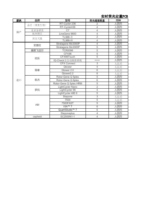
荧光定量PCR仪通道及价格比较表(201407)
耶拿
进口
凯杰
罗氏
ABI
cepheid
光定量PCR仪最新价格
金额(元) 216,480.00 271,920.00 276,000.00 450,000.00 210,000.00 310,000.00 321,530.00 411,625.00 297,606.00 440,500.00 449,500.00 496,000.00 280,500.00 305,660.00 336,660.00 367,660.00 330,040.00 354,628.00 406,040.00 220,000.00 420,000.00 585,000.00 241,400.00 459,028.00 484,600.00 665,440.00 747,630.00 458,000.00 470,000.00 备注 2014质检总局 招标价 网上报价 一中标价:20.58万(淮安市第二人民医院,2014)
单片机解密方法简单介绍(破解)

单片机解密方法简单介绍下面是单片机解密的常用几种方法,我们做一下简单介绍:1:软解密技术,就是通过软件找出单片机的设计缺陷,将内部OTP/falsh ROM 或eeprom代码读出,但这种方法并不是最理想的,因为他的研究时间太长。
同一系列的单片机都不是颗颗一样。
下面再教你如何破解51单片机。
2:探针技术,和FIB技术解密,是一个很流行的一种方法,但是要一定的成本。
首先将单片机的C onfig.(配置文件)用烧写器保存起来,用在文件做出来后手工补回去之用。
再用硝酸熔去掉封装,在显微镜下用微形探针试探。
得出结果后在显微镜拍成图片用FIB连接或切割加工完成。
也有不用FIB用探针就能用编程器将程序读出。
3:紫外线光技术,是一个非常流行的一种方法,也是最简单的一种时间快、像我们一样只要30至1 20分钟出文件、成本非常低样片成本就行。
首先将单片机的Config.(配置文件)用烧写器保存起来,再用硝酸熔去掉封装,在显微镜下用不透光的物体盖住OTP/falsh ROM 或eeprom处,紫外线照在加密位上10到120分钟,加密位由0变为1就能用编程器将程序读出。
(不过他有个缺陷,不是对每颗OT P/falsh都有效)有了以上的了解解密手段,我们开始从最简的紫外光技术,对付它:EMC单片机用紫外光有那一些问题出现呢?:OTP ROM 的地址(Address:0080H to 008FH) or (Address:0280h to 028FH) 即:EMC的指令的第9位由0变为1。
因为它的加密位在于第9位,所以会影响数据。
说明一下指令格式:"0110 bbb rrrrrrr" 这条指令JBC 0x13,2最头痛,2是B,0X13是R。
如果数据由0变为1后:"0111 bbb rrrrrrr"变成JBS 0x13,2头痛啊,见议在80H到8FH 和280H到28FH多用这条指令。
汤姆斯莱斯TX83A系列两线进程循环指示器说明书

1TX83A SeriesTwo-Wire,Process-Loop IndicatorOptional NEMA 4X/7 HousingIntrinsic Safety Certification Intrinsic safety certification allows the TX83A to be used in worst-case hazardous environments with no need for an explosion-proof housing, provided that an intrinsic safety barrier is used to limit the voltage and current that may be introducedin the hazardous environment. FM certification (USA) is for class I, II, III, division 1, groups A, B, C, D, E, F, G. The FM certification number is 5X2AO.AX (3610).Explosion-Proof Housing OptionsTwo external NEMA 7 explosion- proof and NEMA 4X waterproof, sand-cast, copper-free aluminum enclosures with corrosion resistance “safety-blue” polyesterpowder-coating for use in hazardous locations. FM, UL, cUL certification: class I, groups B, C, D; class II, groups E, F, G; and class III,Type 4X.Option EPW3 is a single-height enclosure for one TX83A loop-powered indicator. Option EPW2 is a double-height enclosure for aTX83A loop-powered indicator on top and a TX1500 series isolated 2-wire 4 to 20 mA transmitter on the bottom for indicating transmitter applications. Available with 2 female 1⁄2 NPT pipe fittings, all requiredinternal mounting hardware, and mounting flanges for a wall or bulkhead.U F M IntrinsicSafety Certification U P owered by 1 to 5, 4 to 20 or 10 to 50 mA SignalU 2.5V Max Voltage Drop U 8.9 mm (0.35") LCD U 2000-Count ZeroSuppression or Elevation U 100 to 2000 Count Span Adjust U S electable Dummy Right-Hand ZeroU -40 to 85°C Operation U C ompact, 74 mm (2.9") Dia Diecast HousingU Waterproof to 35 kPa (5 psi)U Shock Resistant to 55 g flow, temperature, or level. Its liquid crystal display provides 31⁄2 active digits, a selectable dummy right-hand zero, and 4 programmable decimal points. Easy to Configure and CalibrateBoth span and zero are fine-tunedwith precision multi-turn potentiometers. These are accessible through holes in the diecast cover, which arenormally sealed with fluorosilicone plugs. Designed for Harsh Environments All versions of the TX83A are rated for operation from -40 to 85°C(-40 to 185°F) with specifiedaccuracy. The case is made ofdiecast metal and is waterproof to35 kPa (5 psi). The electronics arefirmly connected to the case top, so that the meter can withstand highvibration and shock.TX83A with EPW3-ATEX NEMA 4X/7 enclosure.TX83A.TX84.OptionsU 1⁄2 EMT Conduit Fitting U 1⁄2 NPT Pipe Fitting U R elay-Track Mounting Adaptors U E xternal Explosion- Proof HousingURelay-Track MountingAll shown smaller than actual size.TX83A.EPW3-ATEXhousing.The TX83A is a 2-wire current-loop indicator that is powered directly by a 1 to 5 mA, 4 to 20 mA or 10 to 50 mA process loop signal. Noseparate power supply connections are required. This reduces overall hardware and field wiring costs and provides immunity from most electrical noise encountered in process control environments. The electronics are isolated from the case.Readout of Process Variables The TX83A provides extensive zero and span adjustment capability, so that it can read out directly in percent or in engineering units forprocess variables such as pressure,SpecificationsInput Signal: 1 to 5 mA, 4 to 20 mA or 10 to 50 mA (jumper-selectable) Linear Range: 0.3 to 50 mA Protection: 200 mA forward,1000 mA reverseForward Voltage Drop, Maximum:2.5 V up to 50 mAInput Resistance: 50 Ω at 1 to 5 mA, 12.5 Ω at 4 to 20 mA, 5 Ω at 10 to 50 mA Zero Adjust: -2000 to 2000 counts (4 jumper- selectable rangesplus fine adjustment)Span Adjust: 0 to 2000 counts(with fine adjustment)NMR: 46 dB, 50/60 HzCMR (Meter to Case):120 dB, DC to 60 HzCMV (Meter to Case): 700 VpRFI Susceptibility: Less than ±0.5% of span with conduit fitting or external explosion-proof housing in 10V/m field strength at 27 or 440 MHz Accuracy at 25°CMaximum Error:±0.1% of span ±1 count 00 zero tempco ±0.1 count/°C typical,±0.2 count/°C maxSpan Tempco: ±0.005% of span/°C typical, ±0.015% of span/°C max Analog-to-Digital Conversion Technique: Dual-slope, average-value Polarity: AutomaticIntegration Period: 100 msRead Rate: 2.5/sDisplayType: 7-segment LCDHeight: 8.9 mm (0.35")Symbols: -1.8.8.8.0 (31⁄2 active digits plus jumper-selectable dummy right-hand zero)Decimal Points: 4 positions,jumper-selectableOverrange: 3 least-significant active digits blankEnvironmentalOperating Temperature:-40 to 85°C (-40 to 185°F) Vibration: 1.52 mm (0.06") double-amplitude cycled at 10 to 80 Hz Shock: 55 g half-sine, 9 to 13 ms duration Waterproof Pressure: 35 kPa maximum (5 psi)MechanicalWeight: 14 oz (400 g)Diameter: 74 mm (2.9")Height, Including Barrier:48 mm (1.9")Electrical Connections:TX83A: 3-terminal barrier strip with #6 screwsTX84:1⁄2 NPT male pipe fittingwith two 0.3 meter #18 strandedwiresTX84-2: 1⁄2" EMT male conduit fitting with two 0.3 meter #18 strandedwiresMounting MethodsTX83A:• Surface mount with 4 #6 rear-entry screws from backside of bulkhead • Snap mount into 63.5 mm(2.50") relay track• Surface mount with two #8front-entry screwsRequires MAT1 adaptor plateOrdering Examples: TX84 current loop-indicator with NPT pipe mounting.OCW-3The TX83A process-loop indicator may beadded to an existing 4 to 20 mA or10 to 50 mA installation. No additionalwiring is required, since the meter ispowered directly by the current loop.Z SZ S• Snap mount into 69.9 mm (2.75")or 76.2 mm (3.00") relay trackRequires MAT1 adaptor plate• Snap mount into DIN relay trackRequires MDT1 rail clamp• Push mount into explosion proofhousing EPW3-ATEX2。
TPS2554 and TPS2555 Evaluation Module User's Guide
User's GuideSLVU462–June2011TPS2554and TPS2555Evaluation Module This user’s guide describes the evaluation module(EVM)for the TPS2554and TPS2555.TPS2554and TPS2555are precision-adjustable,current-limited,power-distribution switches.The document contains an operational description of the EVM,schematic,board layout,and bill of materials.Contents1Description (2)1.1Features (2)1.2Applications (2)2Schematic (3)3General Configuration and Description (4)3.1Physical Access (4)3.2Current-Limit Setpoint (4)3.3Test Setup (4)4EVM Assembly Drawings and Layout Guidelines (5)4.1Layout Guidelines (5)4.2PCB Drawings (5)5Bill of Materials (8)List of Figures1TPS2554/5EVM Schematic (3)2Typical TPS2554/5EVM Test Setup (5)3Top-Side Placement and Routing (6)4Layer-Two Routing (6)5Layer-Three Routing (7)6Bottom-Side Placement and Routing (7)List of Tables1User Interface (4)2Test Points (4)3EVM Bill of Materials (8)1 SLVU462–June2011TPS2554and TPS2555Evaluation Module Submit Documentation FeedbackCopyright©2011,Texas Instruments IncorporatedDescription 1DescriptionThe TPS2554EVM-010evaluation module allows reference circuit evaluation of the Texas Instruments TPS2554and TPS2555power-distribution switches.1.1Features•Precision adjustable,current-limited,power-distribution switch•Fast overcurrent response–1µs typical•80-mΩ,high-side MOSFET•Operating range:4.5V to5.5V1.2Applications•USB ports/hubs•Notebook personal computers(PC)2TPS2554and TPS2555Evaluation Module SLVU462–June2011Submit Documentation FeedbackCopyright©2011,Texas Instruments IncorporatedGeneral Configuration and Description 3General Configuration and Description3.1Physical AccessTable1lists the TPS2554/5EVM connector functionality,and Table2describes the test point availability.er InterfaceConnector Label DescriptionJ1VIN Input connectorJ2VOUT Output connectorJ3J3Input voltage jumper.Shunt can be removed to measure input current.J4J4Output voltage jumper.Shunt can be removed to measure output current.J5EN Enable jumper.Leave open to enable TPS2554and install shunt to enable TPS2555.J6ILIM_SEL Current limit select.Install shunt to select ILIM0(2.4A nominal),and remove shunt toselect ILIM1(1.2A nominal).D1(RED)FLT Fault LEDTable2.Test PointsTest Point Color Label DescriptionTP3RED IN Power switch input(IC side of J3shunt)TP4BLK GND Power switch input groundTP1WHT FLT Fault pin outputTP2RED VOUT Power switch outputTP5BLK GND Power switch output groundTP6WHT EN Enable pin input3.2Current-Limit SetpointR4and R5configure the current-limit setpoint for ILIM0and ILIM1,respectively(see J6in Table1).ILIM0or ILIM1setpoint can be adjusted using the following example by substituting R4or R5for RILIMx .In thisexample IOS=2A.The following example is an approximation only and does not take into account the resistor tolerance or the variation of ILIM.For exact variation of ILIM,see the TPS2554/TPS2555data sheet,SLVSAM0.IOS=48000/RILIMx=2ARILIMx=48000/IOS=48000/2=24000ΩChoose RILIMx=23.7kΩIOS=48000/23700=2.03A3.3Test SetupFigure2shows a typical test setup for TPS2554/5EVM.4TPS2554and TPS2555Evaluation Module SLVU462–June2011Submit Documentation FeedbackCopyright©2011,Texas Instruments IncorporatedV INOscilloscope EVM Assembly Drawings and Layout GuidelinesFigure2.Typical TPS2554/5EVM Test Setup4EVM Assembly Drawings and Layout Guidelines4.1Layout Guidelines•TPS2554/55placement:Place the TPS2554/55near the USB output connector and the150-µF OUT pin filter capacitor.Connect the exposed pad to the GND pin and the system ground plane using a viaarray.•IN pin bypass capacitance:Place the100-nF bypass capacitor near the IN and GND pins,and make the connection using a low-inductance trace.•ILIM0and ILIM1pin connections:Current-limit accuracy can be compromised by stray current leakage from a higher voltage source to the ILIM0or ILIM1pins.Ensure that adequate spacing existsbetween IN pin copper/trace and ILIM0pin trace to prevent contaminate buildup during the PCBassembly process.If a low-current-limit setpoint is required(RILIMx >200kΩ),use ILIM1for this case,as it is further away from the IN pin.4.2PCB DrawingsThe Figure3through Figure6show component placement and layout of the EVM.5 SLVU462–June2011TPS2554and TPS2555Evaluation Module Submit Documentation FeedbackCopyright©2011,Texas Instruments IncorporatedEVM Assembly Drawings and Layout Guidelines Figure 3.Top-Side Placement and RoutingFigure yer-Two Routing6TPS2554and TPS2555Evaluation ModuleSLVU462–June 2011Submit Documentation FeedbackCopyright ©2011,Texas Instruments Incorporated EVM Assembly Drawings and Layout Guidelinesyer-Three RoutingFigure6.Bottom-Side Placement and Routing7 SLVU462–June2011TPS2554and TPS2555Evaluation Module Submit Documentation FeedbackCopyright©2011,Texas Instruments IncorporatedEvaluation Board/Kit Important NoticeTexas Instruments(TI)provides the enclosed product(s)under the following conditions:This evaluation board/kit is intended for use for ENGINEERING DEVELOPMENT,DEMONSTRATION,OR EVALUATION PURPOSES ONLY and is not considered by TI to be a finished end-product fit for general consumer use.Persons handling the product(s)must have electronics training and observe good engineering practice standards.As such,the goods being provided are not intended to be complete in terms of required design-,marketing-,and/or manufacturing-related protective considerations, including product safety and environmental measures typically found in end products that incorporate such semiconductor components or circuit boards.This evaluation board/kit does not fall within the scope of the European Union directives regarding electromagnetic compatibility,restricted substances(RoHS),recycling(WEEE),FCC,CE or UL,and therefore may not meet the technical requirements of these directives or other related directives.Should this evaluation board/kit not meet the specifications indicated in the User’s Guide,the board/kit may be returned within30 days from the date of delivery for a full refund.THE FOREGOING WARRANTY IS THE EXCLUSIVE WARRANTY MADE BY SELLER TO BUYER AND IS IN LIEU OF ALL OTHER WARRANTIES,EXPRESSED,IMPLIED,OR STATUTORY,INCLUDING ANY WARRANTY OF MERCHANTABILITY OR FITNESS FOR ANY PARTICULAR PURPOSE.The user assumes all responsibility and liability for proper and safe handling of the goods.Further,the user indemnifies TI from all claims arising from the handling or use of the goods.Due to the open construction of the product,it is the user’s responsibility to take any and all appropriate precautions with regard to electrostatic discharge.EXCEPT TO THE EXTENT OF THE INDEMNITY SET FORTH ABOVE,NEITHER PARTY SHALL BE LIABLE TO THE OTHER FOR ANY INDIRECT,SPECIAL,INCIDENTAL,OR CONSEQUENTIAL DAMAGES.TI currently deals with a variety of customers for products,and therefore our arrangement with the user is not exclusive.TI assumes no liability for applications assistance,customer product design,software performance,or infringement of patents or services described herein.Please read the User’s Guide and,specifically,the Warnings and Restrictions notice in the User’s Guide prior to handling the product.This notice contains important safety information about temperatures and voltages.For additional information on TI’s environmental and/or safety programs,please contact the TI application engineer or visit /esh.No license is granted under any patent right or other intellectual property right of TI covering or relating to any machine,process,or combination in which such TI products or services might be or are used.FCC WarningThis evaluation board/kit is intended for use for ENGINEERING DEVELOPMENT,DEMONSTRATION,OR EVALUATION PURPOSES ONLY and is not considered by TI to be a finished end-product fit for general consumer use.It generates,uses,and can radiate radio frequency energy and has not been tested for compliance with the limits of computing devices pursuant to part15 of FCC rules,which are designed to provide reasonable protection against radio frequency interference.Operation of this equipment in other environments may cause interference with radio communications,in which case the user at his own expense will be required to take whatever measures may be required to correct this interference.EVM Warnings and RestrictionsIt is important to operate this EVM within the input voltage range of0V to5.5V and the output voltage range of0V to5.5V. Exceeding the specified input range may cause unexpected operation and/or irreversible damage to the EVM.If there are questions concerning the input range,please contact a TI field representative prior to connecting the input power.Applying loads outside of the specified output range may result in unintended operation and/or possible permanent damage to the EVM.Please consult the EVM User's Guide prior to connecting any load to the EVM output.If there is uncertainty as to the load specification,please contact a TI field representative.During normal operation,some circuit components may have case temperatures greater than85°C.The EVM is designed to operate properly with certain components above85°C as long as the input and output ranges are maintained.These components include but are not limited to linear regulators,switching transistors,pass transistors,and current sense resistors.These types of devices can be identified using the EVM schematic located in the EVM User's Guide.When placing measurement probes near these devices during operation,please be aware that these devices may be very warm to the touch.Mailing Address:Texas Instruments,Post Office Box655303,Dallas,Texas75265Copyright©2011,Texas Instruments IncorporatedIMPORTANT NOTICETexas Instruments Incorporated and its subsidiaries(TI)reserve the right to make corrections,modifications,enhancements,improvements, and other changes to its products and services at any time and to discontinue any product or service without notice.Customers should obtain the latest relevant information before placing orders and should verify that such information is current and complete.All products are sold subject to TI’s terms and conditions of sale supplied at the time of order acknowledgment.TI warrants performance of its hardware products to the specifications applicable at the time of sale in accordance with TI’s standard warranty.Testing and other quality control techniques are used to the extent TI deems necessary to support this warranty.Except where mandated by government requirements,testing of all parameters of each product is not necessarily performed.TI assumes no liability for applications assistance or customer product design.Customers are responsible for their products and applications using TI components.To minimize the risks associated with customer products and applications,customers should provide adequate design and operating safeguards.TI does not warrant or represent that any license,either express or implied,is granted under any TI patent right,copyright,mask work right, or other TI intellectual property right relating to any combination,machine,or process in which TI products or services are rmation published by TI regarding third-party products or services does not constitute a license from TI to use such products or services or a warranty or endorsement e of such information may require a license from a third party under the patents or other intellectual property of the third party,or a license from TI under the patents or other intellectual property of TI.Reproduction of TI information in TI data books or data sheets is permissible only if reproduction is without alteration and is accompanied by all associated warranties,conditions,limitations,and notices.Reproduction of this information with alteration is an unfair and deceptive business practice.TI is not responsible or liable for such altered rmation of third parties may be subject to additional restrictions.Resale of TI products or services with statements different from or beyond the parameters stated by TI for that product or service voids all express and any implied warranties for the associated TI product or service and is an unfair and deceptive business practice.TI is not responsible or liable for any such statements.TI products are not authorized for use in safety-critical applications(such as life support)where a failure of the TI product would reasonably be expected to cause severe personal injury or death,unless officers of the parties have executed an agreement specifically governing such use.Buyers represent that they have all necessary expertise in the safety and regulatory ramifications of their applications,and acknowledge and agree that they are solely responsible for all legal,regulatory and safety-related requirements concerning their products and any use of TI products in such safety-critical applications,notwithstanding any applications-related information or support that may be provided by TI.Further,Buyers must fully indemnify TI and its representatives against any damages arising out of the use of TI products in such safety-critical applications.TI products are neither designed nor intended for use in military/aerospace applications or environments unless the TI products are specifically designated by TI as military-grade or"enhanced plastic."Only products designated by TI as military-grade meet military specifications.Buyers acknowledge and agree that any such use of TI products which TI has not designated as military-grade is solely at the Buyer's risk,and that they are solely responsible for compliance with all legal and regulatory requirements in connection with such use. TI products are neither designed nor intended for use in automotive applications or environments unless the specific TI products are designated by TI as compliant with ISO/TS16949requirements.Buyers acknowledge and agree that,if they use any non-designated products in automotive applications,TI will not be responsible for any failure to meet such requirements.Following are URLs where you can obtain information on other Texas Instruments products and application solutions:Products ApplicationsAudio /audio Communications and Telecom /communicationsAmplifiers Computers and Peripherals /computersData Converters Consumer Electronics /consumer-appsDLP®Products Energy and Lighting /energyDSP Industrial /industrialClocks and Timers /clocks Medical /medicalInterface Security /securityLogic Space,Avionics and Defense /space-avionics-defense Power Mgmt Transportation and /automotiveAutomotiveMicrocontrollers Video and Imaging /videoRFID Wireless /wireless-appsRF/IF and ZigBee®Solutions /lprfTI E2E Community Home Page Mailing Address:Texas Instruments,Post Office Box655303,Dallas,Texas75265Copyright©2011,Texas Instruments Incorporated。
JBL MRX525 音频系统说明书

JBL Incorporated, 8500 Balboa Boulevard, P .O.Box 2200, Northridge, California 91329 U.S.A.J B L M R X 525 R E V HPACKAGE WIRING DIAGRAM03-12T echnical ManualJBL MRX525SPECIFICATIONSACOUSTIC & ELECTRICAL SPECIFICATIONS:•Nominal Impedance: 4 Ohms •Power Capacity:800W / 1600W / 3200W, 2 hrs.(Cont/ Prog/Peak):700W / 1400W / 2800W, 100 hrs • Frequency Range:40 Hz - 20 kHz (-10 dB)•Frequency Response:57 Hz – 20 kHz (±3 dB) •Maximum SPL:129 dB SPL continuous (135 dB SPL peak)•System Sensitivity:100 dB SPL (1 watt @ 1 meter)•Crossover Frequency:1.8 kHzSYSTEM COMPONENTS:•Cabinet:Enclosure (Not for Sale)•Grille:362524-001•Low Frequency 265H-1, 380 mm (15 in) Differential Transducer:Drive woofer •DC Resistance: 5.0 ohm ±10%•High Frequency 2408H, 37.5 mm (1.5 in) annularTransducer:polymer diaphragm, neodymium compression driver•DC Resistance:4.8 ohm +/- 0.2 ohmSYSTEM COMPONENTS:(CONT’D) • Crossover Network:364969-001AURAL SWEEP TEST SPECIFICATIONS:A.System Aural Sweep T est:7.0V Input, 50 Hz to 20 kHzB.L.F .Aural Sweep Test:7.0V Input, 10 Hz to 300 HzC.H.F .Aural Sweep Test:0.75V Input, 200 Hz to 1.5 kHz PHYSICAL SPECIFICATIONS:•Enclosure Dimensions:1240 x 535 x 460 mm D (H x W x D)(48.75 x 21.0 x 18.0 in D)•Net Weight (ea):84.0 lb (38.2 kg)WARRANTY INFORMATION:•Refer to Warranty Statement packed with each product.Warranty 59660Manual362053-001Carton362293-001Fillers (2)362294-002Pkg, Microfoam (8) 49790PPop Sticker 362896-001NETWORK SCHEMATIC - (364969-001)Driver, High Freq 2408H(361549-001X) Driver Repl D8R2408Driver,Low Freq (2)265H(362048-001X)Cone Repl C8R265 265H-1 (2)(363837-003X)Cone Repl C8R265-1Network Assembly 364969-001YEL YEL/BLKGRN GRN/BLKWH/BLK WH NOTE:INDIVIDUAL PARTS FOR THE ABOVE CROSSOVER ARE NOT AVAILABLE.A COMPLETE REPLACEMENT ASSEMBL Y SHOULD BE ORDERED.JBL MRX525804-11110-1610-32 x 1, FLT, PH,BLK OXIDE, LCSNetwork, Input364969-001Screw (6)882-41110-106 x 5/8, PAN, PH,BLK ZINC, LCSNameplate 362051-001Grille Assembly w/ Screen362524-001 Screw (26)882-51110-12Foot (4)353445-001Screw (4)884-41110-1210 x 3/4, PAN, PH,PB, BLK ZINC, LCSDriver, Low Freq (2)265H(362048-001X)Cone ReplC8R265265H-1(363837-003X)Cone ReplC8R265-1Network, Input362292-001Screw (2)882-41110-106 x 5/8, PAN, PH,BLK ZINC, LCS。
华恒科技内部资料

华恒科技ARM产品技术支持信箱:hharm-support@1.华恒的ARM系列产品是否支持ARM ADS(SDT)调试?通过华恒ARM系列产品附带的JTAG烧写工具可以在Windows下使用 Arm Developer Suit (ADS)/SDT 来进行ARM/THUMB模式的C、C++和ASM直接进行源代码级调试和开发。
(1)首先请在 /下载安装PortTalk。
(2) 然后下载/Down/JTAG.exe并把这个文件拷贝到PortTalk的安装目录。
(3)在此目录下为AllowIO.exe建立一个快捷方式,在快捷方式的属性对话框中输入目标路径:“[ PortTalk所在路径 ]\AllowIo.exe JTAG.exe /a ”如果PC操作系统为Win98则只需下载/Down/JTAG.exe假定您的连接开发板和运行JTAG.EXE的计算机的IP为192.168.1.113, 则按照以下步骤:(1)将开发板通过JTAG和计算机连接。
(2)双击运行为AllowIO建立的快捷方式。
(3)运行AWD或ARM Debugger后在Debugger Configuration中设定Target Environment为Remote_A,然后点击Configure按钮,选择Ethernet模式,IP设置为192.168.1.113, 选中HeartBeat选项。
(4)全部配置完毕。
2.关于嵌入式LINUX鉴于ARM7系列平台全部为NOMMU系统,它上面运行的都是uClinux,因此关于这部分的uClinux相关的常见问题可参阅华恒HHCF(uClinux)系列产品常见问题解答:/chinese/hhco5272r1faq.html3.关于AT91烧写的问题操作目录/HHARMAT91-R1/jtag-rw ;mincom波特率:38400;采用串口下载的方式。
大致步骤:先通过JTAG烧写redboot.bin到flash(以后可以不用接JTAG直接烧写),然后烧写linux.bin,最后烧写romfs.img(1). ./AJFlash A -f redboot.bin -s 0 -l 131072(131072为0x80000的十进制数, 表示写入的字节数, 应大于linux.bin的长度) (此命令你可以做成一个批处理文件,省去执行这么一长串的命令) 烧写完后拔掉电源,再拔去jtag烧写器接口(不要带电拔插).(2).重启开发板,在minicom中显示的信息应如下所示:RedBoot> ),在此提示符下键入fis init(3). load -r -v -b 0x02020000 -m xMODEM然后按Ctrl-A S(先按Ctrl+A, 松开再按S), 在出现的菜单里选择xMODEM传送方式 , 这时minicom会显示文件选择对话框, 提示你输入要传送的文件名称, 直接按回车, 输入uClinux内核镜像的文件名, 比如/HHARMAT91-R1/image/linux.bin, 回车, 如果一切顺利, 就可以看到传送进度窗口显示出来, 大概2,3分钟可以传完. 但若要选择路径的话,可用空格键和上下键头键配合选择不同的路径。
- 1、下载文档前请自行甄别文档内容的完整性,平台不提供额外的编辑、内容补充、找答案等附加服务。
- 2、"仅部分预览"的文档,不可在线预览部分如存在完整性等问题,可反馈申请退款(可完整预览的文档不适用该条件!)。
- 3、如文档侵犯您的权益,请联系客服反馈,我们会尽快为您处理(人工客服工作时间:9:00-18:30)。
TMH-QPSR 2-3/1997OLGA - A dialogue system with an animatedtalking agent∗Jonas Beskow 1, Kjell Elenius 1 & Scott McGlashan 21Department of Speech, Music and Hearing, KTH, Stockholm 2Swedish Institute for Computer Science, Stockholm now at Ericsson Radio Systems, StockholmE-mail: beskow@speech.kth.se, kjell@speech.kth.se, scott.mcglashan@era-t.ericsson.seAbstractThe object of the Olga project is to develop an interactive 3D animated talking agent. A futuristic application scenario is interactive digital TV, where the Olga agent would guide naive users through the various services available on the network. The current application is a consumer information service for microwave ovens. Olga required the development of a system with components from many different fields: multimodal interfaces, dialogue management, speech recognition,speech synthesis, graphics, animation, facilities for direct manipulation and database handling. To integrate all knowledge sources Olga is implemented with separate modules communicating with a central dialogue interaction manager. In this paper, we mainly describe the talking animated agent and the dialogue manager. There is also a short description of the preliminary speech recogniser used in the project.∗Also published in Proceedings of Eurospeech -97, 5th Eurospeech Conference on Speech Communication and Technology, Rhodes, Greece, Sept 22-25, 1997.IntroductionAs spoken dialogue systems for simple information services begin to move from the laboratory into the area of technology, research interest is increasing turning to the integration of spoken dialogue interfaces with other modalities such as graphical interfaces. Apart from the general advantages of allowing an alternative input and output modality, speech can compensate for some of the apparent limitations of a graphical interface. Advantages include increased speed of interaction, higher bandwidth (attention and attitude expressed through stress and prosody, etc.) and ability to describe objects not visually present. Conversely, the graphical interface can compensate for limitations of speech, e.g., by making immediately visible the effects of actions upon objects and indicating through the display which objects are currently salient for the system.By including an animated agent in the interface, several positive effects can be antici-pated. The system will seem more anthropo-morphic, which will make users more com-fortable with the dialogue situation. The character can provide a link between the spoken and the visual information domains, being able to refer to graphical items in the interface, using gaze and pointing. Body language, facial expression and gaze can potentially be very useful communication channels in a spoken interface. Furthermore, proper lip-synchronised articulation will improve intelligibility of system utterances, as shown in Beskow et al. (1997).The Olga ProjectIn the Olga project, we have developed a multi-modal system combining a dialogue interface with a graphical user interface, which provides consumer information about microwave ovens.The domain: Microwave ovensAn original motivation for the Olga project was to ease the access to electronic information systems for people who are unfamiliar with computers. They still constitute a substantialBeskow et al.: OLGA - A dialogue system with an animated talking agentpart of the population in all ages, with a pre-dominance of elderly people. The selected con-sumer information application indicates the ambition to make Olga an instrument for the general public. Furthermore, the Swedish Con-sumer Agency (Konsumentverket) was parti-cipating during the initial stages of the project, and they provided a database with facts about microwave ovens.Four main componentsThe system is composed of four main com-ponents: a speech and language understanding component; a direct manipulation interface which provides graphical information and widgets for navigation; an animated talking agent; and a dialogue manager for co-ordinating interpretation and generation in these modalities. Previous researchCompared with previous research in the area, the novelty of Olga lies in that it integrates interactive spoken dialogue, 3-D animated facial expressions, gestures, lip-synchronised audio-visual speech synthesis and a graphical direct manipulation interface. Cassel et al. (1994) have modelled speech and gesture in dialogue using two virtual agents, but no user interaction. Katashi & Akikazu (1994) employed animated facial expressions, but no gestures, as a back-channelling mechanism in a spoken dialogue system. Thorisson (1997) used a 2-D animated character together with input from many sources, including speech and gaze, to model mainly the social aspects of multimodal dialogue interaction. The Waxholm project at the Department of Speech, Music and Hearing (1995), which in some aspects can be seen as a predecessor to Olga, uses a human-like face for the talking agent, and utilises, for example, eye-gaze to refer to various on-screen items such as timetables.The behaviour of the Olga agent is modelled using rules and parameterised templates; for example, the interaction strategies are based on condition-action rules where the condition part refers to the current interactional state as well as user input, and the action part to schematic descriptions of behaviour in language, graphics, and gestures. Similarly, in the animation module, realisation of a particular gesture is achieved by invoking the selected gesture’s template and supplying appropriate parameters. This approach has worked well in our task domain allowing the agent’s behaviour to be easily and quickly extended, as well as facilitating software maintenance.The dialogue managerThe dialogue manager is based on techniques developed in a speech dialogue interface for telephone-based information systems in different languages (McGlashan, 1996, and Eckert & McGlashan, 1993).A tri-partite modelA tri-partite model of interaction is responsible for semantic, task and dialogue interpretation. The semantics component provides a context-dependent interpretation of user input, and is capable of handling anaphora and ellipsis. A task component embodies navigation strategies to efficiently obtain information from the user necessary for successful database access. The dialogue component adopts an 'event-driven' technique for pragmatically interpreting user input, and producing system responses, compare Giachin & McGlashan (1997). On the basis of user input events, it updates a dialogue model composed of system goals and dialogue strate-gies. The goals determine the behaviour of the system, allowing for confirmation and clari-fication of user input (to minimise dialogue breakdown), as well as requests for further information (to maximise dialogue progress). The dialogue strategies are dynamic so that the behaviour of the system varies with progress. A more detailed description of the dialogue manager may be found in Beskow & McGlashan (1997).MultimodalityIn order to manage multimodal dialogues, input and output need to be informationally compatible at the dialogue management level. A user may provide input via buttons in the interface and the agent generate a spoken response; or a user may refer linguistically to an object which the agent realised graphically. Consequently, all input and output is represented in the semantic description language used for spoken input (McGlashan, 1996). This language also allows the user to use different modalities in the same response: e.g. clicking on an object, and then speaking a command to apply to it.Output modality selectionThe dialogue manager decides which modality to use for agent output. In general, modality selection is defined in terms of characteristics of the output information, and the expressiveness and efficiency of the alternative modalities forTMH-QPSR 2-3/1997 realising it. In practice, selection is determined byrules which specify realisation in the threemodalities depending on the action or state whichthe agent wants to express. Table 1 provides asimplified representation of rules (the rules cantake in account other aspects of the action orstate). Goals with a control or feedback functionare realised in speech and gesture: for example,success in understanding user input is indicatedwith a head nodding gesture, while failure isindicated by speaking an explanation of thefailure together with raised eyebrows and themouth turned down. In cases where the databaseaccess has required relaxation of productconstraints, speech and a ‘regret’ gesture arerealised. Product information itself is presentedin speech and graphics: detailed productinformation is displayed while the agent gives aspoken overview. Finally, a print action is simplyindicated with a graphical icon.Table 1.Output modality selection rules. Condition Speech Graphics Gesture reference successstateno no yesreference failurestateyes no yesconstraint relaxationstateyes no yesinform action yes yes yes printing action no yes noThe animated agentThe Olga character is a three dimensional cartoon-like robot lady that can be animated in real time. It is capable of text-to-speech synthesis with synchronised movements of lips, jaw and tongue. It also supports gesture and facial expression that can be used to add emphasis to utterances, support dialogue turn-taking, visually refer to other on-screen graphics such as illustrations and tables, and to indicate the system’s internal state: listening, understanding, uncertain, thinking (i.e., doing time-consuming operations such as searching a database), etc.The parameterised polygon modelThe Olga character (Figure 1) is implemented as a polygon model, consisting of about 2500 polygons that can be animated at 25 frames per second on a graphics workstation. The character was first created as a static polygon representation of the body and head, including teeth and tongue. This static model was then para-meterised, using a general deformation para-meterisation scheme. The scheme allows a deformation to be defined by a few basic properties such as transformation type (rotation, scaling or translation), area of influence (a list of vertex-weight pairs that defines which polygon vertices should be affected by the transformation and to what extent) and various control points for normalisation of the deformation. It is then possible to define non-rigid deformations such as jaw opening, lip rounding, etc., by combining basic deformations. Not only articulatory parameters, but also control of eyebrows, eyelids and smiling are defined in this manner. The body was parameterised by introduction of rotational joints at the neck, elbows, wrists, fingers etc. Speech and articulationOne important reason for using an animated agent in a spoken interface is that it actually will contribute, sometimes significantly, to the intelligibility of the speech, given that mouth movements are properly modelled, compare LeGoff et al. (1994). This is especially true if the acoustic environment is bad, due to for example noise or cross-talk, or if speech perception is impeded by hearing impairment. In a recent experiment, we found that the Olga-character increased the overall intelligibility of VCV-stimuli in noise from 30% for synthetic voice only, to 47% for the synthetic voice and synthetic face combination (Beskow et al. (1997). Articulation is controlled by a rule-based text-to-speech system framework (Carlson & Granström Figure 1. Wireframe and shaded representations of the Olga character.Beskow et al.: OLGA - A dialogue system with an animated talking agent(1997). Trajectories for the articulatory parameters are calculated using a set of rules that account for co-articulation effects. This rule set was originally developed for an extended version of the Parke model (1982) (Beskow, 1995). However, the articulation parameters of the Olga character are chosen to conform to those of the extended Parke model. This makes it possible to drive Olga’s articulation using the same set of rules. Once the parameter trajectories are calculated, the animation is carried out in synchrony with play-back of the speech waveform, which in turn is generated by a formant filter synthesiser controlled by the same rule-synthesis framework.Complex gesturesSpeech movements are calculated on an utterance-by-utterance basis and played back with high control over synchronisation. Body movements and non-speech facial expressions, on the other hand, place different requirements on the animation system. Say for example that we want the agent to dynamically change it’s expression during a user utterance, depending on the progress of the speech recognition. In this case, obviously utterance-by-utterance control will not do. The basic mechanism for handling this kind of movements in the Olga system is the possibility to, at any specific moment, specify a parameter trajectory as a list of time-value pairs to be evaluated immediately. Using such trajec-tory commands, gesture templates can be defined by grouping several commands together as procedures in a high-level scripting language (Tcl/Tk). This allows for complex gestures, such as “shake head and shrug” or “point at graphics display”, that require many parameters to be updated in parallel, to be triggered by a simple procedure call.Arguments for pointing and shruggingSince a general scripting language is used, gesture templates can also be parameterised by supplying arguments to the procedure. For example, a pointing gesture might take optional arguments defining direction of pointing, dura-tion of the movement, degree of effort, etc. As another example, a template defining a “shrug”gesture can have a parameter for selecting one from a set of alternative realisations, ranging from a simple eyebrow movement to a complex gesture involving arms, head, eyebrows and mouth corners. During the course of the dialogue, appropriate gestures are invoked in accordance to messages sent from the dialogue manager. There is also an “idle loop”, invoking various gestures when nothing else is happening in the system. The scripting approach makes it easy to experiment with new gestures and control schemes. This sort of template based handling of facial expressions and gestures has proven to be a simple, yet quite powerful way of managing non-speech movements in the Olga system. The Direct Manipulation InterfaceAll visualisation in the Olga system, except for the Olga agent, is controlled by the Direct Manipulation Interface, DMI. It manages graphics output as well as user initiated input. The output may be used for displaying interactive menus, information tables and/or visualisations, e.g., photos of specific microwave ovens. The graphics component of the DMI is based on the Distributed Interactive Virtual Environment developed at the Swedish Institute of Computer Science (Hagsand, 1996), which simplifies real-time manipulation of displayed 3D objects.The speech recogniserThe Olga project was originally planned for two years, where the addition of the speech recogniser was scheduled for the second year. The intention was to make Wizard-of-Oz simulations with the Olga system during the first year of the project in order to collect speech and language material to be used for the training of the recogniser. However, due to various circumstances it later became evident that an Olga demonstrator had to be built during the first year. In order to get a better conception of Olga's intended functionality, it was decided to include a preliminary speech recognition facility.The speech input module is based on the Waxholm recogniser described in Ström (1996). This is a software only continuous speech recognition engine with different modes for the phonetic pattern matching. In particular, standard multiple Gaussian mixtures and arti-ficial neural networks are implemented for phone probability estimation. Thus, recognition may be performed either in a standard HMM or in a hybrid ANN/HMM framework. A lexicon with multiple pronunciations and a class bigram-grammar is used. The lexicon and grammar constraints are represented by a lexical graph, optimised for efficient lexical decoding. TheTMH-QPSR 2-3/1997decoding is performed in a two-pass search. The first pass is a Viterbi beam-search and the second is an A* stack-decoding search. Multiple recognition hypotheses can be output either as standard N-best lists or in a more compact word-graph format.The recogniser was modified to interact with the dialogue interaction manager and speech input was enabled over the Internet. The current version of the Olga speech recogniser is very preliminary and only able to recognise sentences according to the written scenario that forms the basis of the Olga demonstrator. AcknowledgementThe original concept of Olga came from Henrik Wahlforss. He initiated and managed the project through the company Nordvis AB. The following organisations also took part: Centre for user oriented IT Design and Department of Speech, Music and Hearing, both at KTH; Department of Linguistics at Stockholm University and Swedish Institute of Computer Science. We would especially like to thank Eva-Marie Wadman and Olle Sundblad for graphical interface design and implementation. The Olga project was funded by Telia Research AB, NUTEK and Stiftelsen för kunskaps- och kompetensutveckling from September 1995 until September 1996. ReferencesBeskow J, Dahlquist M, Granström B, Lundeberg M, Spens K-E, & Öhman T (1997). The Teleface project - Multimodal speech communication for the hearing impaired. In: Proc of Eurospeech ‘97, Rhodes, Greece.Cassel J, Steedman M, Badler N, Pelachaud C, Stone M, Douville B, Prevost S, Achorn B (1994). Modeling the interaction between speech and gesture. Proc of 16th Annual Conference of the Cognitive Science Society, Georgia Institute of Technology, Atlanta, USA.Katashi N & Akikazu T (1994). Speech dialogue with facial displays: multimodal human-computerconversation. Proc of the 32nd Annual Meeting of the Association for Computational Linguistics (ACL-94), 102-109.Thórisson KR (1997). Gandalf: An embodied humanoid capable of real-time multimodal dialogue with people. Proc of First ACM International Conference on Autonomous Agents, Marina del Rey, California, pp 536-537. Bertenstam J, Beskow J, Blomberg M, Carlson R, Elenius K, Granström B, Gustafson J, Hunnicutt S, Högberg J, Lindell R, Neovius L, de Serpa-Leitao A, Nord L & Ström N (1995). The Waxholm system - a progress report. Proc of Spoken Dialogue Systems, Vigsoe, Denmark. McGlashan S (1996). Towards multimodal dialogue management. Proc of Twente Workshop on Langu-age Technology 11, Enschede, The Netherlands. Eckert W & McGlashan S (1993). Managing spoken dialogues for information services. Proc of Eurospeech '93, Berlin, Germany, 3: 1653-1656. Giachin E & McGlashan S (1997). Spoken language dialogue systems. In: Bloothooft G & Young S, eds., Corpus-based Methods in Language Proc-essing, Kluwer, The Netherlands.Beskow J & McGlashan S. Olga - a conversational agent with gestures. (To appear in Proc of Workshop on Animated Interface Agents: Making them Intelligent, Nagoya, Japan).Le Goff B, Guiard-Marigny T, Cohen M & Benoît C, (1994). Real-time analysis-synthesis and intelligibility of talking faces. Proc of the Second ESCA/IEEE Workshop on Speech Synthesis, New Paltz, New York, USA.Carlson R & Granström B (1997). Speech Synthesis. In: Hardcastle W & Laver J, eds., The Handbook of Phonetic Sciences, Oxford: Blackwell Publishers Ltd, 768-788.Parke FI (1982). Parametrized models for facial animation. IEEE Computer Graphics, 2/9: 61-68. Beskow J (1995). Rule-based visual speech syn-thesis. Proc of Eurospeech '95, Madrid, Spain, 1: 299-302.Hagsand O (1996). Interactive MultiUser VEs in the DIVE System. IEEE Multimedia Magazine, vol 3, no 1.Ström N (1996). Continuous speech recognition in the WAXHOLM dialogue system. TMH-QPSR, KTH, Stockholm, Sweden, 4/1996: 67-95.。