水力发电与水轮机简介
水轮发电机组基础知识培训
2.5 混流式水轮机的导水机构: 导水机构由导叶、导叶传动机构(包括转臂、连杆和控制环等)、接力器、顶盖、底 环及轴承组成。 作用:①、当机组的负荷发生变化时,用来调节进入水轮机转轮的水量,改变水轮机的出 力,使其与水轮发电机的电磁功率相应。 ②、正常与事故停机时,用来截断水流,使机组停止转动。 ③、水轮机运行时,使水流按有利的方向均匀地流入转轮。
1.2.2 流量: 单位时间内通过水轮机的水流体积称为流量,其代表符号为Q,单位为m³ /s. 1.2.3 出力和效率: 单位时间内水轮机主轴所输出的功称为水轮机的出力。又可以称为功率,用N表示,单 位用KW表示。 eg:具有一定水头和流量的水流通过水轮机时,水流的出力为: Ns=9.81QH(kw) 但水轮机不可能将水流的出力全部转换和输出,由于水轮机在能量转换的过程中,会 产生一定的损耗,因此水轮机的出力必然小于水流的功率。 水轮机的出力N与水流的功率Ns之比,称为水轮机的效率,用η表示,即 η=N/Ns (%) 由上可得出,水轮机的出力又可写成: N=Nsη=9.81QHη (kw)
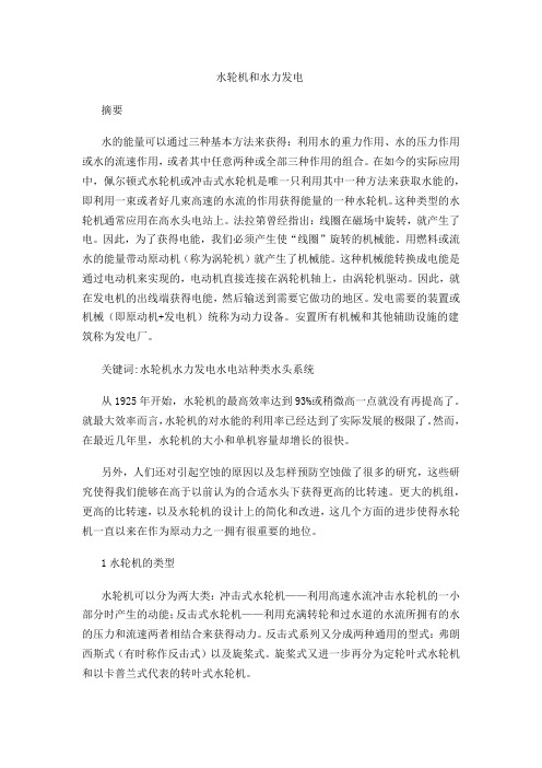
1.3 水轮发电机的分类和型号: 1.3.1 水轮机的类型:
水流的压力能转 变为机械能
水轮机
水流的高速射流动能 转变为机械能
反击式水轮机
斜流式
贯流式
冲击式水轮机
混流式
切击式 双击式
轴流式
斜击式
1.3.1.1
反击式水轮机类型:
①、混流式水轮机:混流式水轮机结构简单,运行可靠, 效率高,应用于水头,大、中、小 型高水头电站 。
水流
水流
斜流式水轮机
1.3.1.2
冲击式水轮机类型:
①、切击式(水斗式)水轮机:结构简单,射流在转轮旋 转平面之内。用于水头大于100m的中、小型高水头小流量 电站。
水力发电中水轮机的性能研究
水力发电中水轮机的性能研究一、引言水力发电是一种利用水能的发电方式,其具有可靠性高、成本低、环保等优点,因此在全球范围内得到广泛应用。
而水轮机作为水力发电中最重要的关键设备,其性能的稳定和高效性直接影响到水力发电的效率和质量。
二、水轮机原理水轮机是利用水能转动轴,从而将机械能转化为电能的一种机械装置。
其原理是利用水的动能和重力势能,转化为机械能。
水从高处流下,撞向水轮叶片,水轮转动带动发电机工作,将机械能转化为电能。
水轮机包括斜流水轮、直流水轮、混流水轮等多种类型,各自的运转原理也有所不同。
三、水轮机的性能参数为了评估水轮机的性能,常常需要考虑以下几种参数:1. 发电机效率:发电机效率是指水能被转化成电能的比率。
其公式为:η=Pe/Pw其中,Pe代表实际输出电功率,Pw代表水轮机水力轴功率。
2. 水轮机效率:水轮机效率是指水能被转化成机械能的比率。
其公式为:ηm=Ws/(ρQH)其中,WS代表水轮机水轮叶轮的机械功率损失,ρ代表水密度,Q代表水流量,H代表水头。
3. 叶轮效率:叶轮效率是指水能被转化成叶轮机械能的比率。
其公式为:ηv=(Ws-Wf)/Wq其中,Ws代表水轮机水轮叶轮的机械功率损失,Wf代表水流流失机械能,Wq代表水的进口机械能。
四、水轮机的性能研究1. 水轮机设计中的材料选择水轮机的叶轮材料直接影响其机械性能和耐久性。
常用的材料有铝合金、不锈钢、碳钢等。
其中,铝合金是一种轻质高强度的材料,其耐腐蚀性和耐疲劳性也较好,因此被广泛应用于小型、高速水轮机的制造。
不锈钢具有优良的耐腐蚀性和抗疲劳性,在某些特殊环境下被广泛应用。
碳钢则因其成本低、制造方便而在工业制造中被广泛采用。
2. 叶轮结构设计优化为了提高水轮机的效率,优化叶轮的设计至关重要。
通过改变叶轮叶片的形状和角度等参数,可以改进叶轮的流动特性,使其更具有动力学效率。
例如,对于混流水轮,合理设计进口角和出口角是提高水轮机效率的关键因素。
水力发电机的工作原理

水力发电机的工作原理水力发电机是一种利用水流的能量来产生电能的机器。
它通过将水的动能转化为机械能,再经由发电机的作用将机械能转化为电能。
水力发电机的工作原理主要包括水流引导、水轮机、发电机和电力传输四个步骤。
1. 水流引导:首先,需要将水源引导至水轮机,以提供动力。
通常,水力发电机会选择位于高海拔的湖泊或水库作为水源,通过建设引水渠道将水流引导至水轮机。
2. 水轮机:水力发电机的核心是水轮机,它将水的动能转化为机械能。
水轮机通常由水轮和轮轴组成,水轮又可分为垂直轴流水轮和水平轴流水轮两种类型。
- 垂直轴流水轮:水流从水轮机的顶部流入,经过水轮的叶片推动水轮转动,然后水从底部排出。
这种水轮机适用于水流较大的情况,旋转速度较慢,通常用于大型水电站。
- 水平轴流水轮:水流从水轮机的一侧流入,推动水轮叶片转动,然后水从另一侧排出。
这种水轮机适用于水流较小的情况,旋转速度较快,通常用于小型水电站。
3. 发电机:水轮机将水流的机械能传递给发电机,发电机则将机械能转化为电能。
发电机由定子和转子组成,通过转子的旋转运动在定子中感应出电流,从而产生电能。
- 交流发电机:大部分水力发电机采用交流发电机,它通过转子的旋转产生变化的磁场,进而在定子中感应出交流电。
交流发电机广泛应用于水力发电站。
- 直流发电机:部分小型水力发电机采用直流发电机,它通过转子的旋转产生恒定的磁场,进而在定子中感应出直流电。
直流发电机常用于家庭小型水力发电设备。
4. 电力传输:发电机生成的电能通常是交流电。
电能通过变压器进行升压、输送和降压处理,最终通过电网传输到各个终端用户,供电使用。
总结:水力发电机工作原理包括水流引导、水轮机、发电机和电力传输四个关键步骤。
通过将水的动能转化为机械能,再经由发电机转化为电能,水力发电机能够有效利用水流资源来产生可再生的电能。
水力发电机在能源行业中扮演着重要的角色,对环境友好且具有可再生特性,是一种可持续发展的能源利用方式。
水力发电的介绍范文
水力发电的介绍范文水力发电是通过利用水的动能转换成机械能,然后再转换成电能的一种可再生能源发电方式。
它是目前世界上使用最广泛的清洁能源之一,具有储能性强、排放少以及对环境影响小等优点。
下面将详细介绍水力发电的原理、分类、应用以及发展趋势。
一、水力发电的原理1.水库式发电:主要通过建设水库、调整水位来控制水流,利用水流的垂直落差和流速将水的动能转换为机械能,最终再转换为电能。
水库式发电具有储能性强的优势,能够更好地适应电力负荷的需求。
2.溪流式发电:适用于山区或河流流速较快的地区,通过设置大坝或引导设施,将水流引导至水轮机上,利用引入的动能将水轮机转动,再利用发电机将机械能转化为电能。
溪流式发电适合于小规模的分散式发电,对生态环境的影响较小,但需满足一定的水流量和高度要求。
3.潮汐式发电:利用潮汐涨落的规律,建设堤坝或涵闸,控制水流进入和排出,从而驱动涡轮机或水轮机发电。
潮汐式发电适用于沿海地区,具有周期性强、可预测性好的特点。
二、水力发电的分类根据水力发电的装机规模、水利工程的类型以及利用水资源的方式,水力发电可分为大型水电站、小型水电站和微型水电站。
1.大型水电站:通常装有数台水轮机和发电机组,于河流中建设大规模的水电站。
这种发电方式能够大规模地储能,满足城市和工业用电的需求,但对水利工程的建设要求较高,且造价较为昂贵。
2.小型水电站:装机容量较小,适合于利用中小型河流水流资源进行发电。
小型水电站的建造相对简单,投资省、效益高,较好地解决了农村电力供应的问题。
3.微型水电站:通常装机容量在10kW以下,适用于村庄和小型农田的电力供应。
在水流资源丰富的地区,微型水电站能够提供可靠的电力供应,满足当地居民的生活需求。
三、水力发电的应用水力发电被广泛应用于城市供电、农村电化等领域。
它可以满足大规模、中小规模和微型的电力供应需求,对经济社会发展具有重要作用。
1.城市供电:大型水电站是城市主要的电力供应方式之一,它能够提供大规模的稳定电力供应,为城市的发展提供保障。
水利工程中常见的机电设备基本知识范本(2篇)
水利工程中常见的机电设备基本知识范本一、水轮机水轮机是一种将水能转换成机械能的装置。
它利用水流的动能和位能来驱动机械设备,是水利工程中常用的机电设备之一。
水轮机包括水轮发电机和透平发电机两大类。
1. 水轮发电机水轮发电机是将水流的动能转换成机械能的装置,通过转换装置将机械能转化为电能。
主要由水轮机、发电机、调速装置等组成。
根据水流的不同特点和发电要求,水轮发电机可以分为混流式、轴流式和离心式。
- 混流式水轮发电机:适用于水头较小、流量大的水利工程。
其特点是水流入口向水轮机轴线的垂直方向流动,水力利用率高,但水轮机结构复杂、体积大。
- 轴流式水轮发电机:适用于大水头、小流量的水利工程。
水流入口和出口都与轴线平行,并且通过导叶的调节来改变进水的流速和流量。
结构简单,但效率相对较低。
- 离心式水轮发电机:适用于水头较大、流量小的水利工程。
通过离心力将水流引入水轮机并转动。
结构简单,但效率较低。
2. 透平发电机透平发电机是利用水流的动能来旋转透平叶片驱动发电机发电的机械装置。
透平发电机主要包括动叶片、静叶片、转子、定子和发电机等部件。
根据叶片的工作方式,透平发电机可以分为常压透平和过压透平两种。
- 常压透平:水流进入透平叶片后,在透平的作用下加速,并通过叶型的转动驱动发电机发电。
适用于水头较小的水利工程。
- 过压透平:在常压的基础上增加水头,以提高发电效率。
适用于水头较大的水利工程。
二、水泵水泵是一种将原始水源或处理后的水流输送到指定地点的机械设备。
水泵利用机械能来增加水流的动能和压力,以便使水流能够流到更高的地方或长距离输送。
1. 根据水泵的工作方式,水泵可以分为离心泵和排污泵两大类。
- 离心泵:水泵内部有一个旋转叶轮,通过转动将水流的动能转化为水流的压力,以便将水流输送至更高的地方。
离心泵适用于输送清水和薄液体。
- 排污泵:排污泵主要用于排放污水或含有固体颗粒的水。
它是通过叶轮的旋转来将污水或含有固体颗粒的水体推送至指定位置。
流体的水力机械和水力发电

流体的水力机械和水力发电流体的水力机械和水力发电在能源领域扮演着重要的角色。
利用水的能量转化为机械能或电能,已经成为一种可持续发展的能源利用方式。
本文将探讨流体的水力机械、水力发电的原理和应用。
一、流体的水力机械流体的水力机械是指将水的能量转化为机械能的设备。
其中,水轮机是最主要的一种水力机械,其利用水的动能驱动转轮旋转,从而产生机械功。
水轮机的结构简单,效率高,已被广泛应用于水电站和其他水力发电设施中。
水轮机按照转轮类型可分为垂直轴水轮机和水平轴水轮机。
其中,水轮机的叶片形状和装配方式对其性能有着重要影响。
目前常见的水轮机叶片形状有直翅叶片和斜翅叶片。
直翅叶片较容易制造、安装和维护,适用于水头较小的场所。
而斜翅叶片则具有更高的效率和适应性,适用于水头较大的场所。
二、水力发电水力发电是指利用流体动能转化为电能的过程。
通过水轮机驱动发电机转子旋转,通过感应电磁感应原理产生电能。
水力发电具有资源丰富、环境友好、可再生等特点,是一种重要的清洁能源。
根据水力发电站的规模和水能资源特点,可以将其分为大型水电站、中型水电站和小型水电站。
大型水电站通常建立在大型河流上,拥有较大的装机容量和水头。
中型水电站则建立在中小型河流上,装机容量相对较小。
而小型水电站则适用于山区和偏远地区,装机容量和发电量较小。
在水力发电站的建设中,需慎重考虑水资源的合理利用和生态环境的保护。
为了减少生态影响,水力发电站应进行生态补偿和环境评估,合理规划水库的建设和水流管理。
三、水力发电的应用水力发电广泛应用于能源供应、农业灌溉、城市供水以及工业生产等领域。
世界各国通过建设水力发电站来满足电力需求,减少对化石燃料的依赖。
此外,水力发电还可以与其他能源进行互补,例如与风能、太阳能等形成混合发电系统,提高能源利用效率。
水力发电还可以用于提供清洁的农业灌溉和城市供水。
通过水力泵站将水源引入农田和城市,可以提高灌溉和供水的效率,并减少对化石燃料的需求。
水轮机和水力发电
水轮机和水力发电摘要水的能量可以通过三种基本方法来获得:利用水的重力作用、水的压力作用或水的流速作用,或者其中任意两种或全部三种作用的组合。
在如今的实际应用中,佩尔顿式水轮机或冲击式水轮机是唯一只利用其中一种方法来获取水能的,即利用一束或者好几束高速的水流的作用获得能量的一种水轮机。
这种类型的水轮机通常应用在高水头电站上。
法拉第曾经指出:线圈在磁场中旋转,就产生了电。
因此,为了获得电能,我们必须产生使“线圈”旋转的机械能。
用燃料或流水的能量带动原动机(称为涡轮机)就产生了机械能。
这种机械能转换成电能是通过电动机来实现的,电动机直接连接在涡轮机轴上,由涡轮机驱动。
因此,就在发电机的出线端获得电能,然后输送到需要它做功的地区。
发电需要的装置或机械(即原动机+发电机)统称为动力设备。
安置所有机械和其他辅助设施的建筑称为发电厂。
关键词:水轮机水力发电水电站种类水头系统从1925年开始,水轮机的最高效率达到93%或稍微高一点就没有再提高了。
就最大效率而言,水轮机的对水能的利用率已经达到了实际发展的极限了。
然而,在最近几年里,水轮机的大小和单机容量却增长的很快。
另外,人们还对引起空蚀的原因以及怎样预防空蚀做了很多的研究,这些研究使得我们能够在高于以前认为的合适水头下获得更高的比转速。
更大的机组,更高的比转速,以及水轮机的设计上的简化和改进,这几个方面的进步使得水轮机一直以来在作为原动力之一拥有很重要的地位。
1水轮机的类型水轮机可以分为两大类:冲击式水轮机——利用高速水流冲击水轮机的一小部分时产生的动能;反击式水轮机——利用充满转轮和过水道的水流所拥有的水的压力和流速两者相结合来获得动力。
反击式系列又分成两种通用的型式:弗朗西斯式(有时称作反击式)以及旋桨式。
旋桨式又进一步再分为定轮叶式水轮机和以卡普兰式代表的转叶式水轮机。
1.1冲击式水轮机在冲击式水轮机上,压力钢管中的水从喷嘴孔口中射出,这时水的的势能转换成动能。
水力机械水轮机发电机水轮发电机组功能

贯流式机组分类
全贯流式:发电机转子安装在水轮机转轮外缘,其 密封困难,现在较少使用。
半贯流式:
灯泡贯流式:发电机组安装在密闭的灯泡体内,使用较 广泛,机组结构紧凑,流道形状平直,水力效率高。
轴伸式贯流机组:发电机安装在外面,水轮机轴伸出到 尾水管外面。
单机容量:几万kW-几十万kW 特点:适用范围广,结构简单,运行稳定,效
率高,适用高水头小流量电站。 三峡水电站即采用了这种水轮机,单机容量70
万kW。是世界上单机容量最大的机组。
混流式水轮机
2. 轴流式: 特点:水流沿转轮轴向流入,轴向流出,水流方
向始终平行于主轴。
适用于大流量、低水头。一般水头在50m以下。 轴流定浆式:叶片不能随工况的变化而转动。高
水流特点:水流从喷嘴射出,沿转轮圆周切线方向冲击 在斗叶上;转轮区水流压力为大气压。
结构特点:由喷嘴和转轮组成,叶片为水斗式。 优点:安装高度不受空化条件限制;应用水头可很高。 适用范围:适用H 变化不大,负荷变化大的电站。
水斗: 特点是由喷嘴出来的射流沿圆周切线方向 冲击转轮上的水斗作功。
最小水头损失送入转轮室。 (2) 导水机构(导叶及控制设备):控制工况。 (3) 转轮(工作核心):能量转换,决定水轮机的尺
2. 反击式水轮机的工作水头 毛水头 - 水头损失=净水头 HG=EA- EB=HM - hI-A
3. 冲击式水轮机的水头 HG=ZU- ZZ - hI-A
其中ZU和ZZ分别为上游和水轮机喷嘴处的水头。
Hale Waihona Puke 4.特征水头(characteristic head) 表示水轮机的运行范围和运行工况。 最大工作水头: Hmax=Z正-Z下min-hI-A 最小工作水头: Hmin=Z死-Z下max-hI-A 设计水头(计算水头) Hr :
- 1、下载文档前请自行甄别文档内容的完整性,平台不提供额外的编辑、内容补充、找答案等附加服务。
- 2、"仅部分预览"的文档,不可在线预览部分如存在完整性等问题,可反馈申请退款(可完整预览的文档不适用该条件!)。
- 3、如文档侵犯您的权益,请联系客服反馈,我们会尽快为您处理(人工客服工作时间:9:00-18:30)。
troduction of hydro-electric power andhydraulicturbinesPower may be developed from water by three fundamental processes : by action of its weight, of its pressure, or of its velocity, or by a combination of any or all three. In modern practice the Pelton or impulse wheel is the only type which obtains power by a single process the action of one or more high-velocity jets. This type of wheel is usually found in high-head developments. Faraday had shown that when a coil is rotat ed in a magnetic field electricity is generated. Thus, in order to produce electrical ener gy, it is necessary that we should produce mechanical energy, which can be used to rot ate the coil. The mechanical energy is produced by running a prime mover by the ene rgy of fuels or flowing water. This mechanical power is converted into electrical powe r by electric generator which is directly coupled to the shaft of turbine and is thus run by turbine. The electrical power, which is consequently obtaind at the terminals of the generator, is then transited to the area where it is to be used fordoing work.he plant or machinery which is required to produce electricity is collectiv ely known as power plant. The building, in the entire machinery along with other aux iliary units is installed, is known as power house.Keywords hydraulic turbines hydro-electric power classification of hydel plants head schemeThere has been practically no increase in the efficiency of hydraulic turbines sinc e about 1925, when maximum efficiencies reached 93% or more. As far as maximum efficiency is concerned, the hydraulic turbine has about reached the practicable limit o f development. Nevertheless, in recent years, there has been a rapid and marked increa se in the physical size and horsepower capacity of individual units.In addition, there has been considerable research into the cause and prevention of cavitation, which allows the advantages of higher specific speeds to be obtained at hig her heads than formerly were considered advisable. The net effect of this progress wit h larger units, higher specific speed, and simplification and improvements in design h as been to retain for the hydraulic turbine the important place which it haslong held at one of the most important prime movers.1. types of hydraulic turbinesHydraulic turbines may be grouped in two general classes: the impulse type which utilizes the kinetic energy of a high-velocity jet which acts upon only a small part of t he circumference at any instant, and the reaction type which develops power from the combined action of pressure and velocity of the water that completely fills the runner and water passages. The reaction group is divided into two general types: the Francis, sometimes called the reaction type, and the propeller type. The propeller class is also f urther subdivided into the fixed-blade propeller type, and the adjustable-blade type of which the Kaplan is representative.1.1 impulse wheelsWith the impulse wheel the potential energy of the water in the penstock is transf ormed into kinetic energy in a jet issuing from the orifice of a nozzle. This jet dischar ge freely into the atmosphere inside the wheel housing and strikes against the bowl-sh aped buckets of the runner. At each revolution the bucket enters, passes through, and p asses out of the jet, during which time it receives the full impact force of the jet. This produces a rapid hammer blow upon the bucket. At the same time the bucket is subjec ted to the centrifugal force tending to separate the bucket from its disk. On account of the stresses so produced and also the scouring effects of the water flowing over the w orking surface of the bowl, material of high quality of resistance against hydraulic we ar and fatigue is required. Only for very low heads can cast iron be employed. Bronze and annealed cast steel are normally used.1.2 propeller runnersnherently suitable for low-head developments, the propeller-type unit has effecte d marked economics within the range of head to which it is adapted. The higher speed of this type of turbine results in a lower-cost generator and somewhat smaller powerh ouse substructure and superstructure. Propeller-type runners for low heads and small outputs are sometimes constructed of cast iron. For heads above 20 ft, they are made of cast steel, a much more reliable material. Large-diameter propellers may hav e individual blades fastened to the hub.1.3 Francis runnersWith the Francis type the water enters from a casing or flume with a relatively lo w velocity, passes through guide vanes or gates located around the circumstance, and flows through the runner, from which it discharges into a draft tube sealed below the t ail-water level. All the runner passagesare completely filled with water, which acts up on the whole circumference of the runner. Only a portion of the power is derived from the dynamic action due to the velocity of the water, a large partof the power being obt ained from the difference in pressure acting on the front and back of the runner bucket s. The draft tube allows maximum utilization of the available head, both because of th e suction created below the runner by the vertical column of water and because the ou tlet of he drafttube is larger than the throat just below the runner, thus utilizing a part of the kinetic energy of the water leaving the runner blades.1.4 adjustable-blade runnersThe adjustable-blade propeller type is a development from the fixed-blade propel ler wheel. One of the best-known units of this type is the Kaplan unit, in which the bla des may be rotated to the most efficient angle by a hydraulic servomotor. A cam on th e governor is used to cause the bladeangle to change with the gate position so that hig h efficiency is always obtained at almost any percentage of full load.By reason of its high efficiency at all gate openings, the adjustable-blade propell er-type unit is particularly applicable to low-head developments where conditions are such that the units must be operated at varying load and varying head. Capital cost an d maintenance for such units are necessarily higher than for fixed-blade propeller-type units operated at the point of maximum efficiency.2.Hydro-plants may be classified on the basis of hydraulic characteristics as foll ow:① run-off river plants .②storage plants.③pumped storage plants.④tidal plants.They are described below.(1) Run-off river plants.These plants are those which utilize the minimum flow in a river having no appre ciable pondage on its upstream side. A weir or a barrage is sometimes constructed acr oss a river simply to raise and maintain the water level at a pre-determined level withi n narrow limits of fluctuations, eithersolely for the power plants or for some other pur pose where the power plant may be incidental. Such a scheme is essentially a low hea d scheme and may be suitable only on a perennial river havingsufficient dry weather f low of such a magnitude as to make the development worthwhile.Run-off river plants generally have a very limited storage capacity, and can use water only when i comes. This small storage capacity is provided for meeting the hourly flu ctuations of load. When the available discharge at site is more than the demand the ex cess water is temporarily stored in the pond on the upstream side of the barrage, whic h is then utilized during the peak hours.he various examples of run-off the river pant are: Ganguwal and Kolta power ho uses located on Nangal Hydel Channel, Mohammad Pur and Pathri power houses on Ganga Canal and Sarda power house on Sarda Canal.The various stations constructed on irrigation channels at the sites of falls, also fa ll under this category of plants.(2) Pumped storage plants.A pumped storage plant generates power during peak hours, but during the off-pe ak hours, water is pumped back from the tail water pool to the headwater pool for futu re use. The pumps are run by some secondary power from some other plant in the syst em. The plant is thus primarily meant for assisting an existing thermal plant or some o ther hydel plant.During peak hours, the water flows from the reservoir to the turbine and electricity is generated. During off-peak hours, the excess power is available from some other plant , and is utilized for pumping water from the tail pool to the head pool, this minor plant thus supplements the power of another major plant. In such a scheme, the same wateris utilized again and again and no water is wastedFor heads varying between 15m to 90m, reservoir pump turbines have been devis ed, which can function both as a turbine as well as a pump. Such reversible turbines c an work at relatively high efficiencies and can help in reducing the cost of such a plan t. Similarly, the same electrical machine can be used both as a generator as well as a motor by reversing the poles. The provision of such a scheme helps considerably in i mproving the load factor of the power system.(3) Storage plantsA storage plant is essentially having an upstream storage reservoir of sufficient si ze so as to permit, sufficient carryover storage from the monsoon season to the dry su mmer season, and thus to develop a firm flow substantially more than minimum natur al flow. In this scheme, a dam is constructed across the river and the power house may be located at the foot of the dam such as in Bhakra, Hirakud, Rihand projects etc. the power house may sometimes be located much away from the dam . In such a case, the power house is located at the end of tunnels which carry water from the reservoir. Th e tunnels are connected to the power house machines by means of pressure pen-stocks which may either be underground or may be kept exposed .When the power house is located near the dam, as is generally done in the low he ad installations ; it is known as concentrated fall hydroelectric development. But when the water is carried to the power house at a considerable distance from the dam throu gh a canal, tunnel, or pen-stock; it is known as a divided fall development.(4) Tidal plantsTidal plants for generation of electric power are the recent and modern advancem ents, and essentially work on the principle that there is a rise in seawater during high t ide period and a fall during the low ebb period. The water rises and falls twice a day; each fall cycle occupying about 12 hours and 25 minutes. The advantage of this rise a nd fall of water is taken in a tidal plant. In other words, the tidal range, i.e. the differe nce between high and low tide levels is utilized to generate power. This is accomplish ed by constructing a basin separated from the ocean by a partition wall and installing t urbines in opening through this wall.Water passes from the ocean to the basin during high tides, and thus running the t urbines and generating electric power. During low tide,the water from the basin runs back to ocean, which can also be utilized to generat e electric power, provided special turbines which can generate power for either directi on of flow are installed. Such plants are useful at places where tidal range is high. Ran ce power station in France is an example of this type of power station. The tidal range at this place is of the order of 11 meters. This power house contains 9 units of 38,000 kW.4.Hydro-plants or hydroelectric schemes may be classified on the basis of operati ng head on turbines as follows:① low head scheme (head<15m),②medium head scheme (head varies between 15m to 60 m) ,③high head scheme (head>60m). They are described below:(1) Low head scheme.A low head scheme is one which uses water head of less than 15 meters or so. A r un off river plant is essentially a low head scheme, a weir or a barrage is constructed t o raise the water level, and the power house is constructed either in continuation with the barrage or at some distance downstream of the barrage, where water is taken to the power house through an intake canal.(2) Medium head schemeA medium head scheme is one which used water head varying between 15 to 60 meters or so.This scheme is thus essentially a dam reservoir scheme, although the da m height is mediocre. Thisscheme is having features somewhere between low had sch eme and high head scheme.(3) High head scheme.A high head scheme is one which uses water head of more than 60m or so. A dam of s ufficient height is, therefore, required to be constructed, so as to store water on the ups tream side and to utilizethis water throughout the year. High head schemes up to heigh ts of 1,800 meters have been developed. The common examples of such a scheme are: Bhakra dam in (Punjab), Rihand dam in (U.P.), and Hoover dam in (U.S.A), etc.。