杜肯阀门执行器PUNEMAX pneumatic actuators CP90
ACTUATECH气动执行器说明书

INSTRUCTION MANUALPart turn pneumatic actuatorwith Manual Override-Complete aluminium protection versionGDV60 - GDV3840 GSV30 – GSV19201)GENERAL FEATURES………………………………………………………………………………………………..pg.32)DATASHEET……………………………………………………………………………………………..pg.43)FUNCTIONAL DESCRIPTION……………………………………………..………….…………………….……………pg.54)DANGERS……….………………………………………………………………………………………..pg.75)PART DESCRIPTION……………..………………………………………………………….………………….pg.86)TRUOBLESHOOTING ………………………………………..…………………...…………………….pg.97)DISPOSAL…….………………...………………………………………………………..…………….....pg.9Environmentally friendly handling of the product.1)GENERAL FEATURES ••••••••••••••••••••••••••••••••••••••••••••••••••••••••••••••••••••••••••••••••••••••••••••••••••Actuatech manufacture a manual handwheel override for a wide range of part turn pneumatic actuators.The actuators with manual override are available on Double Acting “GDV” and Spring Return “GSV” versions.- The principle of the manual handwheel override application is to provide the possibility to open and close the valve connected to the actuator when this operation can’t be done with remote control.- Actuatech manual override actuator is itself equipped with an handwheel for manual operations and it doesn’t need any added declutchable gear box. This solution guarantees a compact size and a more light system on the valve.- When the actuator is manual operated it can be locked in Open/Closed position.- Actuator versions for low temperature and high temperature applications allow to operate respectively until temperatures of -50°C and +150°C, thanks to proper kind of lubrication and material for the gaskets.The maintenance should be done by Actuatech trained personnel only.This instruction manual contains important information regarding the Actuatech manual override actuator operation, installation, maintenance and storage.Please read carefully before installation and keep it in a safe place for further reference.Modification reserved. Rev.date 04/2018. No guarantee for accuracy. Older data sheets are invalid 2)DATASHEET•••••••••••••••••••••••••••••••••••••••••••••••••••••••••••••••••••••••••••••••••••••••••••••••••• DOUBLEACTINGNOMINALTORQUE (Nm)ISOFLANGESQUAREØHANDWEELRim pull forces ( N )To obtain thenominal torqueWeight( Kg )Teorical n° of turnsto close / openstarting from theneutral positionA B C DGDV60 60 F05-F07 14 180 19.3 2.8 11 - 99 263.3 137.6 GDV106 106 F05-F07 17 180 27.8 4 13 - 118.5 279.3 154.8 GDV120 120 F05-F07 17 180 33.8 4.5 14 - 122.1 288.4 163.9 GDV180 180 F07-F10 22 220 44.1 6 16 - 144.9 338.1 183.5 GDV240 240 F07-F10 22 220 54.5 8 18 - 156.8 353.7 199.1 GDV360 360 F07-F10 22 300 67.5 10.2 15 - 169.6 398 220.8 GDV480 480 F10-F12 27 300 83.3 13.2 16 - 193.8 440.6 236.4 GDV720 720 F10-F12 27 350 108.8 17.8 19 - 216.6 503.5 282.3GDV960 960 F10-F12 /F1436 350 128.6 23.8 20 - 239.7 518.3 297.1 GDV1440 1440 F12 / F14 36 400 133.5 33.6 25 - 283.5 636.4 365.6GDV1920 1920 F12-F16 /F1446 400 162.5 43 26 - 300.4 653.7 382.9 GDV3840 3840 F16 46 575 243.5 75 30 - 353.3 890.2 537.5SIMPLEACTINGNOMINALTORQUE (Nm)ISOFLANGESQUAREØHANDWEELRim pull forces ( N )To obtain thenominal torqueWeight( Kg )Teorical n° of turnsto close / openstarting from theneutral positionA B C DGSV30 30 F05-F07 14 180 19.3 3.2 11 129.4 - 263.3 137.6 GSV053 53 F05-F07 17 180 27.8 4.5 13 152.1 - 279.3 154.8 GSV060 60 F05-F07 17 180 33.8 4.5 14 169.3 - 288.4 163.9 GSV090 90 F07-F10 22 220 44.1 6.8 16 196.8 - 338.1 183.5 GSV120 120 F07-F10 22 220 54.5 9 18 204.8 - 353.7 199.1 GSV180 180 F07-F10 22 300 67.5 11.7 15 237 - 398 220.8 GSV240 240 F10-F12 27 300 83.3 15.2 16 260.2 - 440.6 236.4 GSV360 360 F10-F12 27 350 108.8 19.5 19 306.6 - 503.5 282.3GSV480 480 F10-F12 /F1436 350 128.6 28.1 20 324.1 - 518.3 297.1GSV720 720 F12 / F14 36 400 133.5 38.8 25 399 - 636.4 365.6GSV960 960 F12-F16 /F1446 400 162.5 50.6 26 414 - 653.7 382.9GSV1920 1920 F16 46 575 243.5 91 30 509 - 890.2 537.5 All the dimensions are in mm, for missing data see standard catalogue .Modification reserved. Rev.date 04/2018. No guarantee for accuracy. Older data sheets are invalid3) FUNCTIONAL DESCRIPTION •••••••••••••••••••••••••••••••••••••••••••••••••••••••••••••••••••••••••••••••••••••••••••••••••• NB: PRIOR TO MANUAL OVERRIDE OPERATE, ENSURE THAT THE ACTUATOR IS FREE FROM PRESSURE.1.Remove the cap to ensure there is no pressure in the actuator2.Engage the manual override and operate as required3.Disconnect the manual override (neutral position)*for standard actuators.TO CLOSE THE VALVETo close the valve turn the wheel in clockwise direction*.TO OPEN THE VALVETo open the valve turn the wheel in counterclockwise direction.* NB: Before commissioning to ensure proper disengagement, perform an ON-OFF maneuver of the actuatorModification reserved. Rev.date 04/2018. No guarantee for accuracy. Older data sheets are invalidNB: WHEN THE ACTUATOR HAS BEEN MANUALLY OPERATED, RETURN TO THE NEUTRAL POSITION PRIOR TO START NORMAL OPERATIONS.NEUTRAL POSITIONWith the screw in neutral position the piston can move freely and the actuator can be driven pneumatically. MANUAL OPERATION GDV : The handwheel turned counter clockwise, pushes the screw and piston inwards. The valve opens. GSV : The handwheel turned clockwise pushes the screw and piston inwards. The valve closes.MANUAL OPERATIONGDV : When the handwheel is turned clockwise, the screwand piston are drawn outwards. The valve closes. GSV : When the handwheel is turned counter clockwise, the screw and the piston are drawn outwards. The valve opens.Modification reserved. Rev.date 04/2018. No guarantee for accuracy. Older data sheets are invalid4)WARNINGS •••••••••••••••••••••••••••••••••••••••••••••••••••••••••••••••••••••••••••••••••••••••••••••••••• a) Don’t disassemble, compressed spring inside.b) Don’t use levers or bars.c) Don’t use the handwheel to lift the actuator.NB:Manual override is not recommended for safety related applications (SIL) as bypass of a security function. In this application, to prevent an unauthorized use, the manual override is provided with a locking device.Modification reserved. Rev.date 04/2018. No guarantee for accuracy. Older data sheets are invalid5)PART DESCRIPTION ••••••••••••••••••••••••••••••••••••••••••••••••••••••••••••••••••••••••••••••••••••••••••••••••••NB: In the case of actuator low or high temperature the pistons and the material of the O ring are different from the standard actuator.Modification reserved. Rev.date 04/2018. No guarantee for accuracy. Older data sheets are invalid6)TROUBLESHOOTING •••••••••••••••••••••••••••••••••••••••••••••••••••••••••••••••••••••••••••••••••••••••••••••••••• POTENTIAL EFFECT OFFAILUREPOTENTIAL CAUSE OF FAILURE SOLUTION Difficult manual operationsBlocked valve Repair or replace the valvePresence of particles inside the actuator due toan incorrect filtration of the airVerify the condition of the supply airand contact ActuatechThe actuator is pressurized Remove supply air7)DISPOSAL •••••••••••••••••••••••••••••••••••••••••••••••••••••••••••••••••••••••••••••••••••••••••••••••••• Our products are designed so that when they are at the end of their life cycle they can be completely disassembled, separating the different materials for the proper disposal and/or recovery. All materials have been selected in order to ensure minimal environmental impact, health and safety of personnel during their installation and maintenance, provided that, during use, they are not contaminated by hazardous substances.The personnel in charge of the product disposal/recovery, must be qualified and equipped with appropriate personal protective equipment (PPE), according to the product size and the type of service for which the device was intended. The management of waste generated during the installation, maintenance or due to the product disposal, is governed by the rules in force in the country where the product is installed, in any case, the following are general guidelines:- The metal components (aluminum/steel) can be restored as raw material;- Seals/sealing elements as contaminated by fluids from other materials and lubrication,must be disposed of.- The packaging materials that come with the product, should be transferred to the differentiated collection systemavailable in the country.。
GRV-气动执行器S922_933
584 322 797 535 1010 748 1223 960 742 480
285 523 418 789 684
380 275
209 468 342 734 608 1000 874
456 330
358 190 624 456 890 722 1156 988 1422 1254
608 440
23.0 15.8
6 20.1 11.5 28.0 19.3 43.7 35.1 59.4 50.7
27.6 19.0
8
21.7 10.1 37.4 25.8 53.1 41.5 68.8 57.2 84.5 72.9
36.8 25.3
10
31.0 16.6 46.7 32.3 62.4 48.0 78.1 63.7 93.8 79.3 46.0 31.6
单作用执行器的选型
在 正 常 工 作 条 件 下 , 单 作 用 执 行 器 考 虑 的 安 全 系 数 为3 0 % - 5 0 % 例如: 阀门需要力矩 =79N.m 安全力矩=79(1+30%)=103N.m气 源压力=5Bar 对 照 单 作 用 执 行 器 输 出 力 矩 表 , 我 们 可 以 查 到S 9 3 3 - 4 3 5 - 6输 出 力 矩 为 空气行程 0°=325N.m 空气行程 90°=273N.m 弹簧行程 90°=155N.m 弹簧行程 0°=103N.m 所有输出力矩均大于我们需求。
23.2 16.9
10
19.0 11.1 28.8 21.2 39.0 31.2 49.1 41.2 59.1 51.2 29.0 21.1
12
24.9 15.4 34.9 25.4 44.9 35.4 54.9 45.4 34.7 25.3
罗托克电动执行机构

IQ继续提供其全部关键性优点, 使它在全世界居领先地位,这 些优点包括:
终身使用 对于任何环境、任何应用,IQ 已成为可靠性的代名词。简明 的设计、双密封的防水外壳、 红外线设定以及全面的保护系 统,使得IQ在可靠的阀门操作 领域居世界领先地位。安心使 用、极低的维护费用、简便的 诊断及更换备件,可让使用者 无需专门记忆其过程。
3
IQ - 简单而无可匹敌的可靠性
阀位测量 可靠的过程控制取决于阀门行 程末端的准确定位,而液压控 制取决于阀门行程中间的准确 定位。拥有专利的非接触式阀 位测量系统则是执行器控制中 最简单的设计。只有一个活动 部件的分解器把输出中心套筒 的旋转转换成电信号,然后与 存储在安全、永久的存储器中 的限位作比较。
q 作为标准功能的内置数据记 录器
q 兼容IrDATM标准,可通过移 动电话或PC机对执行器进行 就地和远程分析
q 为用户提供了更清晰、更多、 更易用的控制和指示功能
q 简单的力矩和阀位控制,使 可靠性得到提高
q 合理的电子工艺 -“系统 集成芯片”技术
q 防腐功能增强
q 控制和指示灵活性提高
q 附加的保护系统
调试简便 用红外线设定器可进行简单、 安全和快速的非侵入式调整。 使用“随按随用”的IQ设定器 可进入和调整执行器的设定, 如力矩值、限位、控制及显示 功能。Rotork提供的、独特的 本安型设定器在任何环境中, 无论动力电源提供与否,均可 对执行器进行非侵入式设定。
排除故障简便 易读的、带有背景照明的显示 器提供了阀门运行状况、控制 和执行器的报警图标。
精密压力调节器Model9000说明书

Precision Pressure Regulators1P r e c i s i o n P r e s s u r e R e g u l Typical Applications• Environmental Analyzers —Helium or Hydrogen Carrier Gas • Precision Nitrogen Control forChemical Analysis• Laboratory and Process GasChromatography applications • Argon Gas Regulation forBioReagent ManufacturingBack Pressure RegulatorModel 9000Precision Pressure RegulatorProduct SpecificationsThe Parker Precision Fluidics Model 9000 Regulator is a compact,spring-loaded, diaphragm operated back pressure regulator. Designed specifically for precision regulation in low-flow gas applications, it controls upstream pressure rather than downstream pressure and is similar to a relief valve in operation. Model 9000 is performance tested under simulated operating conditions and is cleaned for analyticalinstrument service.Features• Direct-acting and non-relieving• Compact design enables panel mounting• All bar stock construction reduces production variation • Bubble tight shut-off• Panel mount applications• Cleaned for Analytical Service Use • Pressure gauge port included •RoHS and REACH compliantPhysical PropertiesPerformance RatingsPerformance Characteristics** Performance characteristics are based on 60 psig (4.14 barg) helium supply pressure at 50 psig (3.45 barg) outlet pressure.2For more information call +1 603 595 1500 or email ppfinfo @Model 9000Typical Flow CurvesTypical Droop (Flow Sensitivity) Curve 30 psig (2.07 barg) Range SpringTypical Droop (Flow Sensitivity) Curve 60 psig (4.14 barg) Range SpringD e v i a t i o n f r o m S e t P r e s s u r e02101001,0003%2%1%0%Flow SCCM Helium PressureD e v i a t i o n f r o m S e t P r e s s u r e2101001,0003%2%1%0%Flow SCCM Helium PressurePrecision Pressure Regulator3P r e c i s i o For more information call +1 603 595 1500 or email ppfinfo @Principle of OperationA backpressure regulator is designed to regulate inlet pressure. The force of the regulator spring holds the valve closed. When the inlet pressure of the process fluid overcomes the spring setting the valve begins to open. Using a backpressure regulator to precisely control upstream gas pressure is typically more accurate than a relief valve.Model 9000Precision Pressure Regulator4For more information call +1 603 595 1500 or email ppfinfo @Mechanical IntegrationDimensionsBasic DimensionsUnits In (cm)Model 9000Precision Pressure Regulator5P r e c i s i o n P r e s s For more information call +1 603 595 1500 or email ppfinfo @Typical Flow DiagramVOC Emissions Monitoring AnalyzerModel 9000Precision Pressure Regulator6For more information call +1 603 595 1500 or email ppfinfo @Ordering InformationInstallation Guide• May be installed in any orientation.• Support inlet and outlet piping to reduce strain on regulator body.Key Things to Remember:• Choice of Diaphragm Materials – Stainless Steel Diaphragms provide extremely low perme-ability. Coated Fabric Diaphragms, available in Buna or FKM, offer unmatched sensitivity.• Fine Pitch Adjusting Stem – 56 threads/in. (2.2 threads/mm) stem for 15 turns resolution pitch on all regulator adjusting stems gives precise control over incremental pressure adjustments.• Bar Stock Construction and Analytical Service Cleaning – Machined from bar stock in your choice of aluminum or stainless steel. All parts are cleaned to procedures developed specifically for analytical service use, minimizing contaminant generation in low-level analyzer applications.• Extensive Choice of Pressure Range – This ensures maximum resolution at specificpressure and temperature requirements.NOTE: In order to provide the best possible solution for your application, please provide the following requirementswhen contacting Applications Engineering: • Media, Inlet & Outlet Pressures • Mimimum Required Flow Rate.Please click on the ORDER ON-LINE button (or go to www.parker .com/prescision fluidics/regulators) to configure your Precision Pressure Regulator. For more detailed information, visit us on the web orcall Applications Engineering.Model 9000Precision Pressure Regulator7P r e c i s i o n Portfolio ReviewModel 4000Flow control from 0.5 slpm to 10 slpmSmaller SizeModel 9000Model 8286Models 8310 & 8311CustomizationContact Division Applications at (603) 595 1500 or ppfinfo @parker .com.PPF PPR - 002/US October 2016© 2016 Parker Hannifin Corporation Parker Hannifin Corporation Precision Fluidics Division 26 Clinton Dr., Unit 103Hollis, NH 03049Flow control from 1 sccm to 3 slpmFlow control from 1 slpm to 40 slpmFlow control from 10 sccm to 1 slpm Back Pressure RegulatorModel 9000Precision Pressure Regulator。
气动执行器结构及原理

气动执行器结构及原理 The final edition was revised on December 14th, 2020.气缸结构与原理学习气动执行机构气动执行机构俗称又称气动执行器(英文:Pneumatic actuator )按其能源形式分为气动,电动和液动三大类,它们各有特点,适用于不同的场合。
气动执行器是执行器中的一种类别。
气动执行器还可以分为单作用和双作用两种类型:执行器的开关动作都通过气源来驱动执行,叫做DOUBLE ACTING (双作用)。
SPRING RETURN (单作用)的开关动作只有开动作是气源驱动,而关动作是弹簧复位。
气动执行机构简介气动执行器的执行机构和调节机构是统一的整体,其执行机构有薄膜式、活塞式、拨叉式和齿轮齿条式。
活塞式行程长,适用于要求有较大推力的场合;而薄膜式行程较小,只能直接带动阀杆。
拨叉式气动执行器具有扭矩大、空间小、扭矩曲线更符合阀门的扭矩曲线等特点,但是不很美观;常用在大扭矩的阀门上。
齿轮齿条式气动执行机构有结构简单,动作平稳可靠,并且安全防爆等优点,在发电厂、化工,炼油等对安全要求较高的生产过程中有广泛的应用。
齿轮齿条式:齿轮齿条:活塞式:气动执行机构的缺点控制精度较低,双作用的气动执行器,断气源后不能回到预设位置。
单作用的气动执行器,断气源后可以依靠弹簧回到预设位置工作原理说明班当压缩空气从A管咀进入时,气体推动双活塞向两端(缸盖端)直线运动,活塞上的齿条带动旋转轴上的齿轮逆时针方向转动90度,阀门即被打开。
此时气动执行阀两端的气体随B管咀排出。
反之,当压缩空气从B官咀进入气动执行器的两端时,气体推动双塞向中间直线运动,活塞上的齿条带动旋转轴上的齿轮顺时针方向转动90度,阀门即被关闭。
此时气动执行器中间的气体随A管咀排出。
以上为标准型的传动原理。
根据用户需求,气动执行器可装置成与标准型相反的传动原理,即选准轴顺时针方向转动为开启阀门,逆时针方向转动为关闭阀门。
杜肯阀门执行器PUNEMAX pneumatic actuators CP90

01
Pneumatic Actuators -
Actuators Parts and Material Table
No.பைடு நூலகம்
1 2 3 4 5 6 7 8 9 10 11 12 13 14 15 16 17 18 19 20 21 22 23 24
Description
Indicator screw Indicator Spring clip Thrust washer Outside washer Body O-ring (pinion top) Bearing(pinion top) Inside washer Cam Pinion Bearing(pinion bottom) O-ring pinion bottom) O-ring(Adjust screw) Nut(Adjust screw) Adiust screw Piston Guide(Piston) Bearing(Piston) O-ring(Piston) Spring O-ring(End cap) End cap Cap screw
Viton/Silicone Dip coating Viton/Silicone Powder polyster painted
02
Pneumatic Actuators -
Operating Principle
Double Acting Actuators
1(ccw)
2(cw)
Qty
1 1 1 1 1 1 1 1 1 1 1 1 1 2 2 2 2 2 2 2 0-12 2 2 8
Standard Meterial
Plastic Plastic Stainless Steel Stainless Steel PTFE Extruded alluminum alloy NBR PTFE PTFE Alloy steel Alloy steel PTFE NBR NBR Stainless Steel Stainless Steel Cast alluminum/casting Engineering plastics PTFE NBR Spring steel NBR Cast alluminum Stainless Steel
气动执行机构俗称气动头又称气动执行器英文Pneumatic

⽓动执⾏机构俗称⽓动头⼜称⽓动执⾏器英⽂Pneumatic⽓动执⾏机构俗称⽓动头⼜称⽓动执⾏器(英⽂:Pneumatic actuator ) 执⾏器按其能源形式分为⽓动,电动和液动三⼤类,它们各有特点,适⽤于不同的场合。
⽓动执⾏器是执⾏器中的⼀种类别。
⽓动执⾏器还可以分为单作⽤和双作⽤两种类型:执⾏器的开关动作都通过⽓源来驱动执⾏,叫做DOUBLE ACTING (双作⽤)。
SPRING RETURN (单作⽤)的开关动作只有开动作是⽓源驱动,⽽关动作是弹簧复位。
⽓动执⾏机构简介⽓动执⾏器的执⾏机构和调节机构是统⼀的整体,其执⾏机构有薄膜式、活塞式、拨叉式和齿轮齿条式。
活塞式⾏程长,适⽤于要求有较⼤推⼒的场合;⽽薄膜式⾏程较⼩,只能直接带动阀杆。
拨叉式⽓动执⾏器具有扭矩⼤、空间⼩、扭矩曲线更符合阀门的扭矩曲线等特点,但是不很美观;常⽤在⼤扭矩的阀门上。
齿轮齿条式⽓动执⾏机构有结构简单,动作平稳可靠,并且安全防爆等优点,在发电⼚、化⼯,炼油等对安全要求较⾼的⽣产过程中有⼴泛的应⽤。
齿轮齿条式:齿轮齿条:控制精度较低,双作⽤的⽓动执⾏器,断⽓源后不能回到预设位置。
单作⽤的⽓动执⾏器,断⽓源后可以依靠弹簧回到预设位置⼯作原理说明班当压缩空⽓从A管咀进⼊⽓动执⾏器时,⽓体推动双活塞向两端(缸盖端)直线运动,活塞上的齿条带动旋转轴上的齿轮逆时针⽅向转动90度,阀门即被打开。
此时⽓动执⾏阀两端的⽓体随B管咀排出。
反之,当压缩空⽓从B官咀进⼊⽓动执⾏器的两端时,⽓体推动双塞向中间直线运动,活塞上的齿条带动旋转轴上的齿轮顺时针⽅向转动90度,阀门即被关闭。
此时⽓动执⾏器中间的⽓体随A 管咀排出。
以上为标准型的传动原理。
根据⽤户需求,⽓动执⾏器可装置成与标准型相反的传动原理,即选准轴顺时针⽅向转动为开启阀门,逆时针⽅向转动为关闭阀门。
单作⽤(弹簧复位型)⽓动执⾏器A管咀为进⽓⼝,B管咀为排⽓孔(B管咀应安装消声器)。
Rotork 阀门执行器安装手册说明书
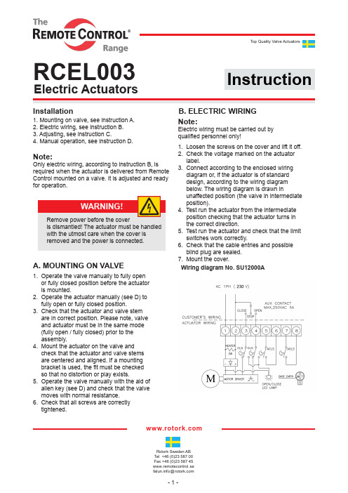
- 1 -Top Quality Valve ActuatorsRotork Sweden AB Tel +46 (0)23 587 00Fax +46 (0)23 587 45www.remotecontrol.se *********************Installation1. Mounting on valve, see instruction A.2. Electric wiring, see instruction B.3. Adjusting, see instruction C.4. Manual operation, see instruction D.Note:Only electric wiring, according to instruction B, is required when the actuator is delivered from Remote Control mounted on a valve. It is adjusted and ready for operation.1. Operate the valve manually to fully open or fully closed position before the actuator is mounted.2. Operate the actuator manually (see D) to fully open or fully closed position.3. Check that the actuator and valve stem are in correct position. Please note, valve and actuator must be in the same mode (fully open / fully closed) prior to the assembly.4. Mount the actuator on the valve and check that the actuator and valve stems are centered and aligned. If a mounting bracket is used, the fit must be checked so that no distortion or play exists.5. Operate the valve manually with the aid of allen key (see D) and check that the valve moves with normal resistance.6. Check that all screws are correctly tightened.Note:Electric wiring must be carried out by qualified personnel only!1. Loosen the screws on the cover and lift it off.2. Check the voltage marked on the actuator label.3. Connect according to the enclosed wiring diagram or, if the actuator is of standard design, according to the wiring diagram below. The wiring diagram is drawn inunaffected position (the valve in intermediate position).4. Test run the actuator from the intermediate position checking that the actuator turns in the correct direction.5. Test run the actuator and check that the limit switches work correctly.6. Check that the cable entries and possible blind plug are sealed.7. Mount the cover.Wiring diagram No. SU12000AA. MOUNTING ON VALVEB. ELECTRIC WIRING WARNING!Remove power before the coveris dismantled! The actuator must be handled with the utmost care when the cover isremoved and the power is connected.InstructionElectric ActuatorsRCEL003- 2 -Rotork Sweden ABBox 80Kontrollvägen 15SE-791 22 FalunSwedenTel +46 (0)23 587 00Fax +46 (0)23 587 45www.remotecontrol.se *********************R e f N o 729 / A r t N o 9807291. Make the final cam adjustments for the limit switches (if necessary) according to instruc- tion (a) below.2. Run the actuator from one end position to the other a number of times.3. Adjust the indicator for visual indicationso that it relates to the valve position. by loosen ing the bolt and turning the indicator to the proper position, then retighttening the bolt.4. Test run the actuator and check that the limit indicators are working correctly.5. Mount the cover.1. Pull the Auto-Manual selector lever to Manual position2. Take the attached 6mm Allen key mounted underside the actuator.3. Insert the 6mm Allen key and turn the valve to the required position.4. Turn clockwise to close and anti-clockwise to open.5. Put allen key back in the holder after manual operation.6. Pull the Auto-Manual selector to Auto position.1. Operate the actuator manually to closed position.2. Adjust the cams for closed position (lowercam) marked CLS and 3:rd cam marked ACLS on the electronic card.3. Operate the actuator manually to open position.4. Adjust the cams for open position (uppercam marked OLS and 2:nd cam marked AOLS) on the electronic card.5. Test run the actuator.(a) Adjustment of cams for limit switches:C. ADJUSTINGD. MANUAL OPERATIONWe reserve the right tomake changes without notice.。
- 1、下载文档前请自行甄别文档内容的完整性,平台不提供额外的编辑、内容补充、找答案等附加服务。
- 2、"仅部分预览"的文档,不可在线预览部分如存在完整性等问题,可反馈申请退款(可完整预览的文档不适用该条件!)。
- 3、如文档侵犯您的权益,请联系客服反馈,我们会尽快为您处理(人工客服工作时间:9:00-18:30)。
Protection
Optional Meterial
Hard anodized etc
Viton/Silicone Nickel plated Stainless Steel Viton/Silicone Viton/Silicone
Anodized/Zinc galvaniz e
Stainless Steel
Qty
1 1 1 1 1 1 1 1 1 1 1 1 1 2 2 2 2 2 ial
Plastic Plastic Stainless Steel Stainless Steel PTFE Extruded alluminum alloy NBR PTFE PTFE Alloy steel Alloy steel PTFE NBR NBR Stainless Steel Stainless Steel Cast alluminum/casting Engineering plastics PTFE NBR Spring steel NBR Cast alluminum Stainless Steel
2(cw)
2.Air to Port A forces the pistons outwards, causing the springs to compress, the pinion turns clockwise while the air is being exhausted from Port B. Loss of air pressure on port A, the stored energy in the springs forces the pistons inwards.The pinion turns counterclockwise while air is being exhausted from port A.
2.Air to Port A forces the pistons outwards, causing the pinion to turn clockwise while the air is being exhausted from Port B. Air to Port B forces the pistons inwards, causing the pinion to turn counterclockwise while the air is being exhausted from Port A.
Spring Return Actuators
1(ccw)
1.Air to Port A forces the pistons outwards, causing the springs to compress, the pinion turns counterclockwise while the air is being exhausted from Port B. Loss of air pressure on port A, the stored energy in the springs forces the pistons inwards.The pinion turns clockwise while air is being exhausted from port A.
Pneumatic Actuators -
DessignβConstruction of Pneumatic Actuators
1 ǃ Actuator Body According to the different requirements, the extruded aluminum alloy ASTM6005 Body can be treated with hard anodized powder polyester painted (different colours is available such as blue, orange, yellow etc.), PTFE or Nickel plated. 2 ǃ Pinion The pinion is high-precision and integrative, made from nickelled-alloy steel, full conform to the lastest standards standards of ISO5211, DIN3337, NAMUR.The dimensions can be customized and the stainless steel is available. 3 ǃ Pistons The twin rack pistons are made from Die-casting aluminum treated with Hard anodized or made from Cast steel with galvanization. Symmetric mounting position,long cycle life and fast operation, reversing rotation by simply inverting the pistons. 4 ǃ End caps Die-casting aluminum powder polyester painted in different colours ,PTFE or Nickel plated. 5 ǃ Travel adjustment The two independent external travel stop adjustment bolts can adjust ±5°at both open and close directions easily and precisely. 6 ǃ O-rings NBR rubber O-rings provide trouble-free operation at standard temperature ranges.For high and low temperature applications Viton or Silicone. 7 ǃ Bearings & Guides Made from low friction,long-life compound material,to avoid the direct contact between metals. The maintenance and replacement are easy and convenient. 8 ǃ High performance springs Preloaded coating springs are made from the high quality material for resistant to corrosion and longer service life,which can be demounted safely and conveniently to satisfy different requirements of torque by changing quantity of springs. 9 ǃ Connection Air connection ,position indicator with NAMUR are convenient for mounting accessories such as solenoid valve, limit switch box,positioner.
Viton/Silicone Dip coating Viton/Silicone Powder polyster painted
02
Pneumatic Actuators -
Operating Principle
Double Acting Actuators
1(ccw)
2(cw)
01
Pneumatic Actuators -
Actuators Parts and Material Table
No.
1 2 3 4 5 6 7 8 9 10 11 12 13 14 15 16 17 18 19 20 21 22 23 24
Description
Indicator screw Indicator Spring clip Thrust washer Outside washer Body O-ring (pinion top) Bearing(pinion top) Inside washer Cam Pinion Bearing(pinion bottom) O-ring pinion bottom) O-ring(Adjust screw) Nut(Adjust screw) Adiust screw Piston Guide(Piston) Bearing(Piston) O-ring(Piston) Spring O-ring(End cap) End cap Cap screw
OUTPUT TORQUE OF DOUBLE ACTING ACTUATORS (Unit:Nm) Model 9005D 9006D 9007D 9008D 9009D 9010D 9012D 9014D 9016D 9019D 9021D 9024D 9027D 2 7.7 13.6 19.2 29.4 43.4 62.8 97.9 167.5 255.2 411.2 502.4 738.2 1121.1 2.5 9.8 17.2 24.4 37.4 55.1 79.8 124.4 212.7 324.1 522.4 638.1 937.7 1424.1 3 11.9 20.9 29.6 45.3 66.8 96.7 150.8 258.0 393.1 633.5 773.9 1137.2 1727.1 Air supply pressure (Unit: Bar) 4 4.5 5 5.5 16.0 18.1 20.2 22.3 28.2 31.9 35.6 39.2 40.0 45.2 50.4 55.6 61.2 69.2 77.2 85.1 90.3 102.0 113.7 125.5 130.7 147.7 164.6 181.6 203.7 230.2 256.6 283.1 348.5 393.7 439.0 484.3 531.0 600.0 669.0 737.9 855.8 966.9 1078.1 1189.2 1045.5 1181.2 1317.0 1452.8 1536.2 1735.7 1935.2 2134.7 2333.1 2636.1 2939.1 3242.1 6 24.4 42.9 60.8 93.1 137.2 198.6 309.6 529.5 806.9 1300.4 1588.6 2334.2 3545.1 7 28.5 50.2 71.2 109.0 160.7 232.5 362.5 620.0 944.8 1522.7 1860.1 2733.2 4151.1 8 32.7 57.6 81.6 124.9 184.1 266.5 415.4 710.5 1082.7 1745.0 2131.6 3132.2 4757.1