GBLM-04激光位移传感器1
激光位移传感器功能及相关参数介绍

激光位移传感器,就是以微米(μm)为单位,测量物体的高度、厚度、距离等的传感器,用来检测物体的「有/无」而位移传感器则用于测量「物体移动了几mm的距离」,因此使用较为广泛。
由于这一传感器具备多种优势,从而其具有的功能也较为多样化:
1、量程可设置,至大40 米
2、分辨率1mm,精度1.5mm+d*万分之5
3、数码管实时显示测量结果
4、LED 状态显示
5、电压模拟输出
6、越限继电器输出(支持NPN/PNP)
7、测量距离矫正
8、基本参数设定
9、RS485 接口,支持Modbus RTU 协议
引出线介绍
①黑色,GND;②白色,+24VDC;③蓝色,RS485 A;④紫色,RS485 B;
⑤灰色,4mA~20mA 电流输出
主要参数指标
表1 主要参数指标
以上就是相关内容的介绍,希望对大家了解这一问题会有更多的帮助,同时如有这方面的兴趣或需求,可以咨询一下南京凯基特电气有限公司。
激光位移传感器技术指标

激光位移传感器技术指标嘿,朋友们!今天咱来聊聊激光位移传感器那些事儿。
你说这激光位移传感器啊,就像是我们生活中的一个小魔术棒。
它能超级精确地测量物体的位移,那精度,简直了!就好比你要量一个小芝麻的移动,它都能给你分得清清楚楚。
咱先说说它的测量范围吧。
这就好像是你跑步的赛道,有长有短。
不同的激光位移传感器,它能测量的距离可不一样。
有的能测个几米远,有的那可是能“看”到好几十米开外呢!你想想,这要是在大工程里,能发挥多大作用呀!还有那分辨率,可别小瞧了这一点。
它就像是你手机屏幕的清晰度,分辨率越高,看到的细节就越多。
激光位移传感器的分辨率高了,那测量出来的结果就更准确,误差就更小啦。
你说要是分辨率不行,那不就跟戴了个模糊的眼镜一样,啥都看不清嘛!响应时间也很重要哦!这就跟你反应速度似的。
如果响应时间太长,等它测出来,黄花菜都凉了。
但是好的激光位移传感器,那响应速度,快得让你惊讶!再说说线性度吧,这就好像是一条直直的路。
如果线性度不好,那这条路就弯弯曲曲的,测量结果不就乱七八糟啦?咱可不能要这样的呀!那稳定性呢,就像是一个可靠的朋友。
它得一直稳稳当当的,不能今天测的准,明天就不行了。
这要是不稳定,那多让人头疼呀!哎呀,你说这激光位移传感器是不是很神奇?它在好多领域都大显身手呢!像工业生产啦,科研啦,到处都有它的身影。
咱就说在工业生产里,它能精准地测量零件的尺寸,保证产品的质量。
这就好比是一个严格的质检员,不放过任何一个小瑕疵。
在科研中呢,它能帮助科学家们获得更准确的数据,推动科技的进步。
这不就是给科研加了一把力嘛!你说这么厉害的东西,咱能不好好了解了解吗?咱得知道怎么挑,怎么用,才能让它发挥最大的作用呀!所以啊,大家可别小瞧了这小小的激光位移传感器,它背后的学问可大着呢!它就是那个默默工作,却能带来巨大贡献的小能手。
怎么样,是不是对激光位移传感器有了更深的认识啦?。
激光位移传感器快速入门指南说明书
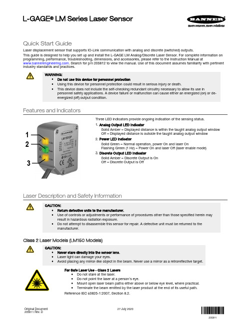
Quick Start GuideLaser displacement sensor that supports IO-Link communication with analog and discrete (switched) outputs.This guide is designed to help you set up and install the L-GAGE LM Analog/Discrete Laser Sensor. For complete information on programming, performance, troubleshooting, dimensions, and accessories, please refer to the Instruction Manual at . Search for p/n 205812 to view the manual. Use of this document assumes familiarity with pertinentindustry standards and practices.WARNING:•Do not use this device for personnel protection•Using this device for personnel protection could result in serious injury or death.•This device does not include the self-checking redundant circuitry necessary to allow its use inpersonnel safety applications. A device failure or malfunction can cause either an energized (on) or de-energized (off) output condition.Features and Indicators132Three LED indicators provide ongoing indication of the sensing status.1. Analog Output LED IndicatorSolid Amber = Displayed distance is within the taught analog output window Off = Displayed distance is outside the taught analog output window 2. Power LED IndicatorSolid Green = Normal operation, power On and laser OnFlashing Green (1 Hz) = Power On and laser Off (laser enable mode)3. Discrete Output LED IndicatorSolid Amber = Discrete Output is On Off = Discrete Output is OffLaser Description and Safety InformationCAUTION:•Return defective units to the manufacturer.•Use of controls or adjustments or performance of procedures other than those specified herein mayresult in hazardous radiation exposure.•Do not attempt to disassemble this sensor for repair. A defective unit must be returned to themanufacturer.Class 2 Laser Models (LM150 Models)CAUTION:•Never stare directly into the sensor lens.•Laser light can damage your eyes.•Avoid placing any mirror-like object in the beam. Never use a mirror as a retroreflective target.For Safe Laser Use - Class 2 Lasers•Do not stare at the laser.•Do not point the laser at a person’s eye.•Mount open laser beam paths either above or below eye level, where practical.•Terminate the beam emitted by the laser product at the end of its useful path.Reference IEC 60825-1:2007, Section 8.2.L-GAGE ® LM Series Laser SensorOriginal Document 205811 Rev. D27 July 2020205811Class 2 LasersClass 2 lasers are lasers that emit visible radiation in the wavelength range from 400 nm to 700 nm, where eye protection is normally afforded by aversion responses, including the blink reflex. This reaction may be expected to provide adequate protection under reasonably foreseeable conditions of operation, including the use of optical instruments for intrabeam viewing.LASER LIGHTDO NOT STARE INTO BEAMCLASS 2 LASER PRODUCTAcc to IEC 60825-1:2007.λ=640-670nm; P=0.45mWPW: 45-1,750msComplies with 21 CFR 1040.10 and 1040.11Except for deviations pursuant to laser noticeNo. 50, Dated June 24, 2007.Figure 1. FDA (CDRH) warning label (Class 2)Class 2 Laser Safety NotesLow-power lasers are, by definition, incapable of causing eye injury within the duration of ablink (aversion response) of 0.25 seconds. They also must emit only visible wavelengths(400 to 700 nm). Therefore, an ocular hazard may exist only if individuals overcome theirnatural aversion to bright light and stare directly into the laser beam.Class 1 Laser Models (LM80 Models)Class 1 lasers are lasers that are safe under reasonably foreseeable conditions ofoperation, including the use of optical instruments for intrabeam viewing.Figure 2. FDA (CDRH) warning label (Class 1) Laser wavelength: 655 nm Output: < 0.33 mW Pulse Duration: 45 µs to 1750 µsInstallation InstructionsSensor InstallationNote: Handle the sensor with care during installation and operation. Sensor windows soiled by fingerprints,dust, water, oil, etc. may create stray light that may degrade the peak performance of the sensor. Blow thewindow clear using filtered, compressed air, then clean as necessary using 70% isopropyl alcohol and cottonswabs or water and a soft cloth.Install the Safety LabelThe safety label must be installed on or near the LM sensors.Note:Position the label on the cable or near the sensor in a location that has minimal chemical exposure.Figure 3. Typical installation; other mounting options are possible.1.Remove the protective cover from the adhesive on the label.2.Wrap the label around the LM cable, as shown.3.Press the two halves of the label together. - Tel: + 1 888 373 6767P/N 205811 Rev. DSensor OrientationCorrect sensor-to-object orientation is important to ensure proper sensing. See the following figures for examples of correct and incorrect sensor-to-object orientation as certain placements may pose problems for sensing distances.Figure 4. Orientation by a wall IncorrectCorrect Figure 5. Orientation in an openingIncorrectCorrectFigure 6. Orientation for a turning objectIncorrectCorrectFigure 7. Orientation for a height difference IncorrectCorrectFigure 8. Orientation for a color or luster difference Figure 9. Orientation for a highly reflective targetApplying tilt to sensor may improve performance on reflective targets. The direction and magnitude of the tilt depends on the application, but a 15° tilt is often sufficient.Mount the Device1.If a bracket is needed, mount the device onto the bracket.2.Mount the device (or the device and the bracket) to the machine or equipment at the desired location. Do not tighten themounting screws at this time.3.Check the device alignment.4.Tighten the mounting screws to secure the device (or the device and the bracket) in the aligned position.Wiring Diagrams+–* Push-Pull output. User-configurable PNP/NPN setting.*Key 1 = Brown 2 = White 3 = Blue 4 = Black 5 = Gray+–* Push-Pull output. User-configurable PNP/NPN setting.*The bare shield wire is connected internally to the sensor housing and should be connected as follows:•If the sensor housing is mounted so that it is in continuity with both the machine frame and earth ground, connect the barewire (also) to earth ground.•If the sensor housing is mounted so that it is insulated from the machine frame and you are experiencing noise, connectingthe bare wire to -V dc (together with the blue wire), may help.•If the sensor is mounted so that it is in continuity with the machine frame, but not with earth ground, do not connect thebare wire (e.g. cut off the bare wire).P/N 205811 Rev. D - Tel: + 1 888 373 67673Configuration InstructionsSensor ProgrammingProgram the sensor using the buttons on the RSD1 remote sensor display accessory, via IO-Link, or the remote input (limited programming options).If you are using the RSD1 for programming, from Run mode, use the buttons to access the Quick Menu and the Sensor Menu. See the instruction manual (p/n 205812) for more information on the options available from each menu. For TEACH options, follow the TEACH instructions in the instruction manual.In addition to programming the sensor, use the remote input to disable the buttons for security, preventing unauthorized or accidental programming changes. See the instruction manual for more information.from Run Mode> 4 sec.Access Sensor Menu Access RSD1 MenuFigure 10. Accessing the MenusRemote Display Buttons and the LMUse the RSD1 buttons Down , Up , Enter , and Escape to view or change RSD1 settings and information and to program a connected sensor.Down and Up Buttons Press Down and Up to:•Access the Quick Menu from Run mode •Navigate the menu systems •Change programming settings•Change individual digit values in distance based settings When navigating the menu systems, the menu items loop.Press Down and Up to change setting values. Press and hold the buttons to cycle through numeric values. After changing a setting value, the value slowly flashes until the change is saved using the Enter button.Enter Button Press Enter to:•Access the Sensor Menu from Run mode •Access the submenus•Move right one digit in distance based settings •Save changesIn the RSD1 Menu, a check mark in the lower right corner of the display indicates that pressing Enter accesses a submenu.Press Enter to save changes. New values flash rapidly, and the sensor returns to the parent menu. - Tel: + 1 888 373 6767P/N 205811 Rev. DEscape ButtonPress and hold Escape for 4 seconds to:•Access the RSD1 Menu while in Run modePress Escape to:•Leave the current menu and return to the parent menuImportant: Pressing Escape discards any unsaved programming changes.In the RSD1 Menu, a return arrow in the upper left corner of the display indicates that pressing Escape returns to the parent menu.Press and hold Escape for 2 seconds to return to Run mode from the RSD1 Menu.Quick MenuThe sensor includes a Quick Menu with easy access to view and change the analog and discrete output switch points.Access the Quick Menu by pressing Down or Up from Run mode. When in the Quick Menu, the current distance measurement displays on the first line and the menu name and the analog value alternate on the second line of the display. Press Enter to access the switch points.Press Down or Up to change the switch point to the desired value.Press Enter to save the new value and return to the Quick Menu.* In Setpoint mode, SPt1 Pt is replaced by SPt and SPt2 Pt is not available.In Dual mode, SPt1 is replaced by DualSPt and SPt2 Pt is not available.Sensor Menu (MENU)Access the Sensor Menu by pressing Enter from Run mode. The Sensor Menu is also accessible from the Quick Menu: navigate to MENU and press Enter. The Sensor Menu includes several submenus that provide access to view and change sensor settings and to view sensor information.P/N 205811 Rev. D - Tel: + 1 888 373 67675SensorMenu Full MapFrom Run mode, press Enter to enter the top-level menu system (A_OUT, D_OUT, INPUT, MEASURE, etc).Top Menu* Factory default setting - Tel: + 1 888 373 6767P/N 205811 Rev. DSpecificationsSupply Voltage (Vcc)10 V dc to 30 V dcUse only with a suitable Class 2 power supply (North America) Power and Current Consumption, exclusive of loadNormal Run Mode: 1.5 W, Current consumption < 62 mA at 24 V dc Supply Protection CircuitryProtected against reverse polarity and transient overvoltages Ambient Light Immunity10,000 luxConstructionHousing: stainless steelWindow: acrylic Sensing BeamVisible red, 655 nmSensing RangeLM80: 40 to 80 mmLM150: 50 mm to 150 mmDelay at Power Up2.1 sMeasurement/Output Rate0.25 ms to 4 ms; user selectable from the Speed menu Output ConfigurationAnalog output: 4 to 20 mA (LM...I Models) or 0 to 10 V DC (LM...U Models)Discrete output: Push/Pull, IO-LinkOutput RatingsDiscrete Output: 50 mA maximum (protected against continuous overload and short circuit)Output saturation voltage (PNP): < 3 V at 50 mAOutput saturation voltage (NPN): < 2.5 V at 50 mAAnalog current output (LM...I Models): 500 Ω maximumAnalog voltage output (LM...U Models): 1000 Ω minimum Maximum Torque1.5 N·mRemote InputAllowable Input Voltage Range: 0 to VccActive Low (internal weak pullup—sinking current):High State: > 3.6 VLow State: < 2.4 VActive High (internal weak pulldown—sourcing current): High State: > Vcc - 2.9 VLow State: < Vcc - 4.6 VMinimum Window Size, Analog and DiscreteLM80:Analog: 1 mmDiscrete: 0.024 mmLM150:Analog: 1 mmDiscrete: 0.1 mm Analog ResolutionLM80: 0.002 mmLM150: 0.004 mmRepeatabilityLM80: ± 0.001 mm1LM150: ± 0.002 mm 2Analog and IO-Link LinearityLM80:40–70 mm: ± 0.02 mm70–80 mm: ± 0.03 mmLM150:50–120 mm: ± 0.06 mm120–150 mm: ± 0.07 mmIO-Link Accuracy3LM80: ± 0.175 mmLM150: ± 0.2 mmTemperature Effect, TypicalLM80: ± 0.006 mm/°CLM150: ± 0.008 mm/°CResponse TimeTotal response speed varies from 0.5 ms to 2048 ms, depending on base measurement rate and averaging settings.See Instruction Manual for more information.Minimum Object SeparationLM80:Uniform targets (6% to 90% reflectivity) 40–70 mm: 0.04 mmUniform targets (6% to 90% reflectivity) 70–80 mm: 0.06 mmNon-uniform targets (6% to 90% reflectivity): 0.4 mmLM150:Uniform targets (6% to 90% reflectivity) 50–120 mm: 0.120 mmUniform targets (6% to 90% reflectivity) 120–150 mm: 0.140 mm Non-uniform targets (6% to 90% reflectivity): 0.8 mm Environmental RatingIEC IP67Operating Conditions–10 °C to +55 °C (+14 °F to +131 °F)90% at +55 °C maximum relative humidity (non-condensing) Storage Temperature–35 °C to 60 °C (–31°F to 140 °F)Boresighting± 0.70 mm at 40 mm± 0.87 mm at 50 mm± 1.40 mm at 80 mm± 2.62 mm at 150 mmVibration/Mechanical ShockMeets IEC 60947-5-2 (10 to 60 Hz max., double amplitude 0.06 in, max acceleration 10G. 30G 11 ms duration, half sine wave) Application NoteFor optimum performance, allow 10 minutes for the sensor to warm upCertificationsUL Type 1with 128× averaging. With 1× averaging, repeatability of ± 0.004 mm from 40 to 80 mm.with 128× averaging. With 1× averaging, repeatability of ± 0.005 mm from 50 to 120 mm and ± 0.010 mm from 120 to 150 mm.3The accuracy specification refers to the possible absolute offset when installing a sensor without taking any reference measurement.Linearity is the more relevant specification for most applications.P/N 205811 Rev. D - Tel: + 1 888 373 67677Typical Beam Spot Size4Required Overcurrent ProtectionWARNING: Electrical connections mustbe made by qualified personnel inaccordance with local and nationalelectrical codes and regulations.Overcurrent protection is required to be provided by endproduct application per the supplied table.Overcurrent protection may be provided with external fusing orvia Current Limiting, Class 2 Power Supply.Supply wiring leads < 24 AWG shall not be spliced.For additional product support, go to.FCC Part 15 and CAN ICES-3 (B)/NMB-3(B)This device complies with part 15 of the FCC Rules and CAN ICES-3 (B)/NMB-3(B). Operation is subject to the following two conditions:1.This device may not cause harmful interference, and2.This device must accept any interference received, including interference that may cause undesired operation.This equipment has been tested and found to comply with the limits for a Class B digital device, pursuant to part 15 of the FCC Rules and CAN ICES-3 (B)/NMB-3(B). These limits are designed to provide reasonable protection against harmful interference in a residential installation. This equipment generates, uses and can radiate radio frequency energy and, if not installed and used in accordance with the instructions, may cause harmful interference to radio communications. However, there is no guarantee that interference will not occur in a particular installation. If this equipment does cause harmful interference to radio or television reception, which can be determined by turning the equipment off and on, the user is encouraged to try to correct the interference by one or more of the following measures:•Reorient or relocate the receiving antenna.•Increase the separation between the equipment and receiver.•Connect the equipment into an outlet on a circuit different from that to which the receiver is connected.•Consult the manufacturer.Banner Engineering Corp. Limited WarrantyBanner Engineering Corp. warrants its products to be free from defects in material and workmanship for one year following the date of shipment. Banner Engineering Corp. will repair or replace, free of charge, any product of its manufacture which, at the time it is returned to the factory, is found to have been defective during the warranty period. This warranty does not cover damage or liability for misuse, abuse, or the improper application or installation of the Banner product.THIS LIMITED WARRANTY IS EXCLUSIVE AND IN LIEU OF ALL OTHER WARRANTIES WHETHER EXPRESS OR IMPLIED (INCLUDING, WITHOUT LIMITATION, ANY WARRANTY OF MERCHANTABILITY OR FITNESS FOR A PARTICULAR PURPOSE), AND WHETHER ARISING UNDER COURSE OF PERFORMANCE, COURSE OF DEALING OR TRADE USAGE. This Warranty is exclusive and limited to repair or, at the discretion of Banner Engineering Corp., replacement. IN NO EVENT SHALL BANNER ENGINEERING CORP. BE LIABLE TO BUYER OR ANY OTHER PERSON OR ENTITY FOR ANY EXTRA COSTS, EXPENSES, LOSSES, LOSS OF PROFITS, OR ANY INCIDENTAL, CONSEQUENTIAL OR SPECIAL DAMAGES RESULTING FROM ANY PRODUCT DEFECT OR FROM THE USE OR INABILITY TO USE THE PRODUCT, WHETHER ARISING IN CONTRACT OR WARRANTY, STATUTE, TORT, STRICT LIABILITY, NEGLIGENCE, OR OTHERWISE.Banner Engineering Corp. reserves the right to change, modify or improve the design of the product without assuming any obligations or liabilities relating to any product previously manufactured by Banner Engineering Corp. Any misuse, abuse, or improper application or installation of this product or use of the product for personal protection applications when the product is identified as not intended for such purposes will void the product warranty. Any modifications to this product without prior express approval by Banner Engineering Corp will void the product warranties. All specifications published in this document are subject to change; Banner reserves the right to modify product specifications or update documentation at any time. Specifications and product information in English supersede that which is provided in any other language. For the most recent version of any documentation, refer to: .For patent information, see /patents.© Banner Engineering Corp. All rights reserved。
激光位移传感器原理

激光位移传感器原理激光位移传感器是一种利用激光技术来测量目标物体位置的传感器。
它通过测量激光束和目标物体之间的距离来实现精准的位移测量,具有高精度、快速响应、非接触测量等优点,被广泛应用于工业自动化、机器人技术、精密加工等领域。
本文将介绍激光位移传感器的原理及其工作过程。
激光位移传感器的原理是基于激光测距技术,利用激光束与目标物体之间的反射光信号来测量目标物体的位移。
其工作原理主要包括激光发射、光束聚焦、反射光接收和信号处理等步骤。
首先,激光位移传感器通过激光发射器发射一束激光,激光束经过透镜的聚焦作用后,形成一个非常细小的光斑,然后照射到目标物体上。
当激光束照射到目标物体表面时,会产生反射光,反射光经过透镜再次聚焦后,进入光电探测器进行接收。
光电探测器接收到反射光信号后,将其转换成电信号,并经过信号处理电路进行放大、滤波和数字化处理,最终得到目标物体与传感器之间的距离信息。
激光位移传感器通过测量激光束与目标物体之间的距离,可以实现对目标物体位置的高精度测量。
激光位移传感器的工作过程非常简单,但却能够实现高精度的位移测量。
其原理是基于激光的直线传播特性和反射光的接收特性,利用光电探测器将反射光信号转换成电信号,并进行信号处理得到目标物体的位移信息。
由于激光束具有高能量密度和方向性好的特点,因此激光位移传感器具有快速响应、高精度、非接触测量等优点,适用于对目标物体位置要求较高的场合。
总之,激光位移传感器是一种利用激光技术实现位移测量的高精度传感器,其原理是基于激光的直线传播和反射光的接收特性,通过测量激光束与目标物体之间的距离来实现位移测量。
激光位移传感器具有快速响应、高精度、非接触测量等优点,被广泛应用于工业自动化、机器人技术、精密加工等领域。
希望本文能够帮助读者更好地理解激光位移传感器的原理及其工作过程。
激光位移传感器IL_IM使用说明书
ᇣᖗ 表示若不遵守该注意事项,可能导致人员遭受轻微或中度的伤害。
⊼ᛣ
表示若不遵守该注意事项,将导致本产品损害以及财产损失。
䞡㽕
表示使用过程中,必须遵守的注意事项和使用限制等。
㽕⚍
表示正确使用本产品所必须注意的其它信息。
খ㗗
表示为了更好地理解和使用有关信息所给出的一些小诀窍。
IL 系列产品的安全信息
IL Series-IM_C
2
安装放大器
DIN 导轨安装型,主单元 (IL-1000)
将主机壳底部的卡爪与 DIN 导轨对齐。 在按照箭
(3)
头(1)方向推动主机壳的同时,沿着箭头(2)
的方向倾斜放大器。
取下放大器,沿着箭头(3)的方向抬起主机壳,
(2)
(1)
同时按照箭头(1)的方向推动主机壳。
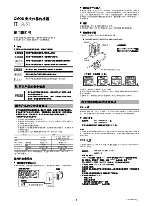
• IL-S025: 25 mm ±0.25 mm • IL-030: 30 mm ±0.25 mm • IL-S065/IL-065: 65 mm ±0.5 mm
• IL-100: 100 mm ±1 mm • IL-300: 300 mm ±7 mm • IL-600: 600 mm ±20 mm
• 本产品可在海拔 2000 m 及 2000 m 以下使用。 • 只能在室内使用。 • 在安装传感头电缆以及传感头连接电缆时,必须注意避免机械损伤(例如绝缘层破
裂等)。 • 放大器单元的电源电缆和 I/O 电缆只能在内部接线。 • 以下电缆的额定电压为 30 V:
- 传感头电缆 - 传感头连接电缆 - 放大器单元的电源电缆和 I/O 电缆 • 电缆安装时,应当远离 30 V 以上的电路。
• 适用标准: CAN/CSA C22.2 No.61010-1 UL61010-1
激光位移传感器操作手册说明书

激光位移传感器操作手册V3.0目录第1章:产品概要......................................................................... 1-11.1 包装内容 ......................................................................................... 1-11.2 各部件名称及功能........................................................................... 1-21.3 安装................................................................................................. 1-3 第2章:设定与测量 ..................................................................... 2-1 第3章:软件操作......................................................................... 3-13.1 通信设置 ......................................................................................... 3-13.2 位置读取与归零设定 ....................................................................... 3-2 第4章:通讯指令......................................................................... 4-14.1 通讯参数列表 .................................................................................. 4-14.2 通讯协议 ......................................................................................... 4-4 第5章:产品规格......................................................................... 5-1 第6章:安全注意事项.................................................................. 6-1 第7章:保固 ................................................................................ 7-1版本更新历程激光位移计操作手册V3.0版本更新历程版本更新日期V1.0 第一版发行2018/09/03V2.0 新增「反应速度设定」与「中值滤波器设定」功能说明与通讯地址设定方式。
激光位移传感器的研究与应用

激光位移传感器的研究与应用摘要激光位移传感器,凭借其高精度测量与非接触操作的独特优势,在工业自动化及科学研究的广阔舞台占据了举足轻重的地位。
本研究深入剖析了激光位移传感器的工作原理、关键技术要素,及其在多领域应用的实例,并对该传感器的性能进行了全面审视与优化探索。
研究证实,该技术能够精准检测细微位移变化,为工业生产线的质量监控、物料精确定位,以及科研中微观形变的精密测量等提供了坚实的数据保障。
在技术升级的努力下,通过激光源的改良、光学系统优化及信号处理技术的增强,传感器的精确度与稳定性均实现了显著提升。
此外,激光位移传感器在智能机器人、交通监控等新兴应用领域的潜力逐渐显现,预示着其应用范围的不断拓展。
随着技术创新步伐的加快,激光位移传感器无疑将在更多领域绽放光彩,为相关行业的发展注入强劲动力。
关键词:激光位移传感器;高精度测量;非接触式测量;工业自动化;科研实验;性能优化;新兴领域应用目录摘要 (1)第一章引言 (3)1.1 激光位移传感器的研究背景 (3)1.2 激光位移传感器的应用意义 (4)1.3 当前研究现状及研究方法 (5)第二章激光位移传感器原理与技术 (7)2.1 激光测距原理 (7)2.2 关键技术分析 (8)2.3 传感器特点 (9)第三章激光位移传感器的应用实例 (11)3.1 工业自动化领域的应用 (11)3.2 科研实验领域的应用 (12)3.3 其他领域的应用 (12)第四章激光位移传感器的性能评估与优化 (14)4.1 性能评估指标 (14)4.2 性能优化方法 (14)第五章激光位移传感器市场前景与挑战 (16)5.1 市场前景分析 (16)5.2 行业挑战与机遇 (16)第六章结论与展望 (18)6.1 研究结论 (18)6.2 未来研究方向与展望 (18)第一章引言1.1 激光位移传感器的研究背景激光位移传感器,凭借其高精度和非接触式的测量特性,近年来在工业界和科研领域均受到了广泛的关注和应用。
激光位移传感器的标定_于正林
激光位移传感器的标定于正林1,乔夫涛1,王一尘2(1.长春理工大学机电工程学院,长春130022;2.吉林大学生物与农机工程学院,长春130022)摘要:介绍了一种基于高精度光栅尺标定激光位移传感器的方法。
该标定装置使用步进电机控制挡板的移动,光栅尺和激光位移传感器同时采集挡板移动的距离,计算机通过数据采集卡采集光栅尺和激光位移传感器的数据。
本装置的结构设计符合阿贝原则,同时详细介绍了标定装置的原理、组成结构和数据处理。
关键词:标定;激光位移传感器;光栅尺;阿贝原则中图分类号:TH71文献标识码:A文章编号:1672-9870(2013)(3-4)-0032-03Calibration of Laser Displacement SensorYU Zhenglin 1,QIAO Futao 1,WANG Yichen 2(1.College of Mechanical and Electrical Engineering ,Changchun University of Science and Technology ,Changchun 130022;2.School of Biological and Agricultural Engineering,Jilin University,Changchun 130022)Abstract :In this paper ,a method of calibration of laser displacement sensor based on high precision grating scale is in-troduces.In this equipment ,step motor control the motion of dam board ,and grating scale and laser displacement sen-sor get the distance of dam board ’s puter collect the data of the grating scale and laser displacement sen-sor by DAQ Card.The structural design of this equipment accords with Abbe ’s principle .This paper gives a detailed introduction of this calibration equipment ’s theory ,construction and data processing.Key words :calibration ;laser displacement sensor ;grating scale ;Abbe ’s principle激光位移传感器是利用激光技术进行测量的传感器,是一种将位移的变化转变成电信号变化的测量装置。
- 1、下载文档前请自行甄别文档内容的完整性,平台不提供额外的编辑、内容补充、找答案等附加服务。
- 2、"仅部分预览"的文档,不可在线预览部分如存在完整性等问题,可反馈申请退款(可完整预览的文档不适用该条件!)。
- 3、如文档侵犯您的权益,请联系客服反馈,我们会尽快为您处理(人工客服工作时间:9:00-18:30)。
GBLM-04 测距传感器
一、产品说明:
传感器数字输出接口:RS232/RS485/RS422(更换接口方式,只需更换通讯电缆即可)
传感器模拟输出接口(可选):4-20mA/0-2.5V/0-5V/0-10V(可反向输出,可以任意设置4和20MA对应的距离值,即上下限)
传感器开关量输出口(可选):最多四路,输出方式有5V电压(默认值)、12V电压、与供电电压一致、光耦输出四种方式,输出方式不能通过命令进行修改请提前说明。
开关量输出可以能过命令来设置输出触发点、输出状态(大于触发点和小于触发点的的输出状态)。
传感器最大测量频率:10Hz(连续测量时,数据返回时间可以调整,最短100mS,最长
105,000mS)
传感器测量方式:连续测量和单次测量两种
传感器操作方式:命令操作和自动操作(上电后自动进入连续测量状态)
激光波长:635nm(620 -- 690nm)
测量精度:正负1mm
测量距离:0.05-- 40m
外形尺寸:133 * 65 * 35mm(安装尺寸可按客户要求做)
电源电压:6-30V
温度范围:-8℃到40℃(可加做恒温系统,其温度范围可以扩展到-40℃到50℃)
串口设置:9600,n,8,1
二、可通过命令设置的功能:
1、传感器地址(一条总线上挂多个传感器时使用)
2、连续测量返回数据时间间隔(100MS-105S)
3、量程上下限(只对模拟输出有效,量程上下限分别对应20MA或4MA)
4、模拟输出方式(只对模拟输出有效),可以使量程上下限分别对应最大电流值、最小电流值,或最小、最大电流值。
5、测距起始点,可以使返回数据由传感器头部开始,或由传感器尾部分开始算起
6、开关量输出点及输出方式
7、每个传感器有唯一的一个序列号,可以通过命令读取。
注:本机标准配置不带模拟输出接口,不带开关量输出接口,如有需要请在定货时说明。
三、产品特点:
1. 后端接口只用一个DB15(军工级)接口,前端为有机玻璃透明窗,壳体为完整一体。
以上特点
保证了其密封性;
2. 本款测距传感器为统一标准,更改数据输出方式,测量方式等时,只需要更换后端数据电缆即
可,无需要对传感器体做任何改动;
3. 数据电缆上有透明窗,在传感器工作时可以看到电源、数据接收、数据发送三个指示灯,使工作
人员在没有电脑或其他设备的情况下,依然可以对传感器的工作状态一目了然。
注:本传感器可设置的参数
1、可设置地址(适合于多机单总线通讯)
2、可设置量程(可设置最小,最大量程,但只对模拟输出有效)
3、可设置模拟量输出方式, 即可以模拟量随距离增加而增加或随距离增加而减小
4、可设置连续测量状态下,数据返回时间间隔
5、可设置距离测量起始端, 即为前端或尾端为距离起始点本传感器可以通过命令读取型号和生产编号,以查看是否和外标签一致来确定其真伪。