法国Active Audio2016年最新产品资料
法国Active audio
法国Active audioACTIVE AUDIO是一个来自法国的高端间隔阵列扬声器品牌,它由Xavier Meynial于2001年4月成立。
成立伊始,ACTIVE AUDIO便获得了ANV AR大奖(French National Research Reward Agency)。
ACTIVE AUDIO的产品包括有SA100P,SA180P,SA250P,SA250S 这四种型号,它们都拥有ACTIVE AUDIO获得专利的DGRC技术(Digital and Geometric Radiation Control)。
与传统的每个扬声器都需要独立控制的系统相比,DGRC的主要优点是它可以大大减少需要控制的通道的数量,即可以把电子部分从声柱中分离出来,从而带来更小巧的尺寸,更方便的维护和更高的性价比。
ACTIVE AUDIO间隔阵列扬声器是诸如火车站、机场、游泳馆、教堂、购物中心、会议厅、演讲厅、礼堂、博物馆、历史建筑等大容积公共场所扩声的理想选择。
R 100 新一代无源阵列扬声器产品介绍新一代无源阵列扬声器R100是一个1米高的无源阵列扬声器,基于专利技术DGRC原理,由于DGRC原理的应用,确保听众去获得高清晰度的声压级。
R100 是中大型复杂场所扩声的最理想选择(如:机场、火车站、教堂、音视频会议室、多功能厅、大型购物广场、主题公园等,基于本身的防水性能,R100也适合用在户外扩声。
R100有两个版本:R100(低阻8欧);R100T(100V 定压)SA400P DSP 间隔阵列扬声器产品特性连续声压级覆盖(±3dB)最大:68 m连续声压级覆盖(±5dB)最大:90 m水平覆盖角度(-6dB,在1kHz - 2kHz):180°IP保护指数:IP54最大声压级(粉红噪声):95dB在40m带宽:220Hz - 18kHz尺寸:4000×124×151 mm重量:39 kg需要的功率放大器通道数量:63"扬声器单元数量:49SA250S DSP 间隔阵列扬声器产品特性连续声压级覆盖(±3dB)最大:28 m连续声压级覆盖(±5dB)最大:36 m水平覆盖角度(-6dB,在1kHz - 2kHz):180°IP保护指数:IP45最大声压级(粉红噪声):95dB在20m带宽:220Hz - 16kHz尺寸:2505×124×151 mm重量:24 kg需要的功率放大器通道数量:63"扬声器单元数量:30SA250P DSP 间隔阵列扬声器产品特性连续声压级覆盖(±3dB)最大:28 m连续声压级覆盖(±5dB)最大:36 m水平覆盖角度(-6dB,在1kHz - 2kHz):180°IP保护指数:IP45最大声压级(粉红噪声):95dB在20m带宽:220Hz - 16kHz尺寸:2505×124×151 mm重量:24 kg需要的功率放大器通道数量:63"扬声器单元数量:30SA180P DSP 间隔阵列扬声器产品特性连续声压级覆盖(±3dB)最大:30 m连续声压级覆盖(±5dB)最大:40 m水平覆盖角度(-6dB,在1kHz - 2kHz):180°IP保护指数:IP45最大声压级(粉红噪声):95dB在15m带宽:220Hz - 16kHz尺寸:1840×124×135 mm重量:17 kg需要的功率放大器通道数量:33"扬声器单元数量:22SA100P DSP 间隔阵列扬声器产品特性连续声压级覆盖(±3dB)最大:30 m连续声压级覆盖(±5dB)最大:40 m水平覆盖角度(-6dB,在1kHz - 2kHz):180°IP保护指数:IP45最大声压级(粉红噪声):95dB在15m带宽:220Hz - 16kHz尺寸:1840×124×135 mm重量:17 kg需要的功率放大器通道数量:33"扬声器单元数量:22SA12 低音扬声器产品介绍这款低音是专为间隔阵列扬声器而配置,增强音乐播放的丰满度及语言的生动感。
2016 Ford Focus技术规格说明书
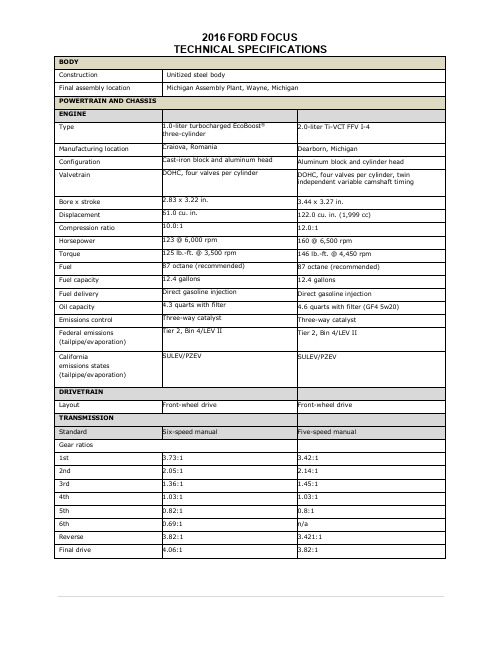
2016 FORD FOCUS TECHNICAL SPECIFICATIONS
DIMENSIONS (inches unless otherwise noted)
Four-door sedan
Four-door hatchback
EXTERIOR
Wheelbase
104.3
104.3
Length Width, excluding mirrors Height Track, front, rear INTERIOR Seating capacity Front headroom Front legroom, maximum Front shoulder room
SE Luxury Package, available on SE EcoBoost Appearance Package Titanium Titanium Handling Package
2016 FORD FOCUS
TECHNICAL SPECIFICATIONS
Six-speed automatic with SelectShift®
1.0-liter, six-speed manual
30 mpg city, 42 mpg highway, 35 mpg combined
.
1.0-liter, six-speed PowerShift automatic with SelectShift
28 mpg city, 40 mpg highway, 32 mpg combined
California emissions states (tailpipe/evaporation)
2.83 x 3.22 in. 61.0 cu. in. 10.0:1 123 @ 6,000 rpm 125 lb.-ft. @ 3,500 rpm 87 octane (recommended) 12.4 gallons Direct gasoline injection 4.3 quarts with filter Three-way catalyst Tier 2, Bin 4/LEV II
Acoustimass 5 系列 V 和 Acoustimass 3 系列 V 立体扬音器系统用户指

Regulatory InformationThis symbol means the product must not be discarded as household waste, and should be delivered to an appropriate collection facility for recycling. Proper disposal and recycling helps protect natural resources, human health and the environment. For more information on disposal and recycling of this product, contact your local municipality, disposal service, or the shop where you bought this product.Bose Corporation hereby declares that this product is in compliance with the essential requirements and other relevant provisions of Directive 1999/5/EC and all other applicable EU directive requirements. The complete declaration of conformity can be found at: /compliance.Names and Contents of Toxic or Hazardous Substances or ElementsPart Name Toxic or Hazardous Substances and ElementsLead (Pb)Mercury (Hg)Cadmium (Cd)Hexavalent (CR(VI))Polybrominated Biphenyl (PBB)Polybrominated d iphenylether (PBDE) PCBs X00000Metal parts X00000Plastic parts000000Speakers X00000Cables X000000: Indicates that this toxic or hazardous substance contained in all of the homogeneous materials for this part is below the limit requirement in SJ/T 11363-2006.X: Indicates that this toxic or hazardous substance contained in at least one of the homogeneous materials used for this part is above the limit requirement in SJ/T 11363-2006.Please complete and retain for your records.The serial numbers are located on the connector panel of the Acoustimass® module.Serial Number: _________________________________________________________________________________________________________________________ Model Number:_________________________________________________________________________________________________________________________ Purchase date: _________________________________________________________________________________________________________________________ Please keep your receipt together with this owner’s guide.©2015 Bose Corporation. No part of this work may be reproduced, modified, distributed, or otherwise used without written permission.2 - EnglishTable of Contents IntroductionAbout your Bose® Acoustimass® stereo speaker system (4)System features (4)Unpacking the system (4)Setting UpPlacement guidelines (5)Sample system placement (5)Connecting the speakers to the Acoustimass module (6)Mounting the speakers (6)Connecting the Acoustimass module to your receiver or amplifier (7)Before plugging in your receiver or amplifier (7)Checking the system (7)Understanding automatic system protection (7)Care and MaintenanceTroubleshooting (8)Cleaning (8)Customer service (8)Limited warranty (8)Accessories (8)Technical informationCompatibility (9)Wire recommendations (9)English - 3About your Bose® Acoustimass® stereo speaker systemThe Bose Acoustimass stereo speaker system delivers spacious, true sound from small, h igh-performance speakers for consistent audio performance regardless of content, source or room layout.System Features• Bose Acoustimass speaker technology delivers full, natural audio performance.• Hideaway Acoustimass module provides impactful bass sound.• Speakers can be mounted on the wall, table stands or floor stands (kits available separately).Unpacking the systemCarefully unpack the carton and confirm that the following parts are included:WARNING: This product contains magnetic material. Contact your physician if you have questions on whether this might affect the operation of your implantable medical device.Acoustimass module Rubber feet(2) speaker wires(2) speaker cablesAcoustimass 5 system(2) Direct/Reflecting® series II speakers Acoustimass 3 system(2) Virtually Invisible® series II speakersNote: If part of the system is damaged, do not use it. Contact your authorized Bose dealer or Bose Customer Service. Refer to thec ontact sheet in the carton.Introduction4 - EnglishSetting Up Placement guidelinesPlace the system outside of and away from metal cabinets, other audio/video components and direct heat sources.Acoustimass® Module• Stand the module on its rubber feet along a wall within 5 ft. (1.5 m) of the corner. To increase bass, move the module closer to a corner.• Choose a stable and level surface. Vibration can cause the module to move, p articularly on smooth surfaces like marble,glass or highly polished wood.• Leave at least 2 in. (50 mm) of space between the opening and the wall.• Place at least 2 ft. (0.6 m) from any TV to avoid magnetic interference with the TV image. Move it farther away if you stillnotice interference.Speakers• Place the speakers 3 - 15 ft. (1- 4.6 m) apart.• Place the speakers at least 6 in. (.15 mm) away from any CRT (picture tube) TV.Sample system placementAcoustimass 5 systemNote: Attach the rubber feet to the Acoustimass module to protect your floor.CAUTION: Do not place the Acoustimass module on its front or back panel when in use.English - 56 - EnglishConnecting the speakers to the Acoustimass moduleUse the two provided speaker cables to connect your speakers to the Acoustimass module.CAUTION: Turn off and unplug all components before making the connections.1. Insert the left speaker cable’s L plug into the left speaker, with the label facing down.2. Insert the right speaker cable’s R plug into the right speaker, with the label facing down.CAUTION: Do not connect your amplifier or receiver directly to the speakers. Connect the speakers to the A coustimass module to avoiddamaging your system.3. Connect the other end of the left speaker cable to the L (left) OUTPUTS TO CUBE SPEAKERS terminal on the connector panel ofthe Acoustimass module.A. Insert the marked wire into the positive (+) terminal (with the red marking).B. Insert the unmarked wire into the negative (–) terminal (with the black marking). 4. Repeat step 3 for the right speaker cable, connecting its wires to the R (right) terminal.–R+–L +OUTPUTSTO CUBE SPEAKERS–R +–L +INPUTSFROM AMP OR RECEIVERMounting the speakersYou can place system speakers on wall brackets, table stands or floor stands. You can also use additional speaker wire and a Bose connector to increase the distance between the speakers and the A coustimass module. To purchase these accessories, contact your local Bose dealer or visit w CAUTION: Do not use any other hardware to mount the speakers.Setting UpRLAcoustimass 3 systemAcoustimass 5 systemEnglish - 7Setting UpConnecting the Acoustimass ® module to your receiver or amplifierThe speaker wires without plugs connect the Acoustimass module to your receiver or amplifier. Your speaker system works withr eceivers or amplifiers rated from 10 to 200 watts per channel with 4 to 8 ohm impedance. Refer to your receiver or amplifier owner’s guide.CAUTION: Incorrect wiring results in little or no bass output and could damage the system.1. Connect the speaker wires to the INPUTS FROM AMP OR RECEIVER terminals on the Acoustimass module’s rear panel:A. Connect the marked wire to the positive (+) terminal of the L (left) pair of input terminals.B. Connect the unmarked wire to the negative (–) terminal of the L (left) pair of input terminals.C. Repeat steps A and B with the other speaker wire for the R (right) pair of input terminals.–R +–L +OUTPUTSTO CUBE SPEAKERS–R +–L +INPUTSFROM AMP OR RECEIVER2. Connect the other ends of the cables to the speaker terminals of your amplifier or receiver.A. Connect the marked wire connected to the L (left) pair of input terminals on the module to the LEFT positive (+) terminal on youramplifier or receiver. B. Connect the unmarked wire connected to the L (left) pair of input terminals on the module to the LEFT negative (–) terminal onyour amplifier or receiver.C. Repeat steps A and B with the wire connected to the R (right) pair of input terminals on your Acoustimass module and theRIGHT pair of input terminals on your amplifier or receiver.–R+–L +OUTPUTSTO CUBE SPEAKERS–R+–L +INPUTSFROM AMP OR RECEIVERBefore plugging in your receiver or amplifier:• Ensure no strands of wire from any terminal are brushing against any other terminal. Such “bridged” wires create short circuits which can damage your receiver or amplifier.• Check all connections to avoid damaging your speakers. Make sure the speakers are connected to the module and not directly to the amplifier or receiver.Checking the systemWith your amplifier and Acoustimass ® module powered, your system should respond accordingly:• With the balance control on your amplifier turned to the left, sound comes from the Acoustimass module and left speaker only.• With the balance control turned to the right, sound comes from the Acoustimass module and right speaker only.• With the balance control in the center position, music with bass should be the same or louder with the control in the center than to the left or right.If your system does not respond as described, check all the wires for proper positive to positive and negative to negative connections. If your system still doesn’t respond properly, see “Troubleshooting” on page 8.Understanding automatic system protectionWhen played at high volume, your Acoustimass systems’ automatic protection circuit activates to prevent damage to the system from electrical stress or overload. When this happens, you may notice a slight decrease in volume. This indicates that the power input may have exceeded safe levels. Setting the volume at or above this level for sustained periods is not r ecommended.Care and MaintenanceTroubleshootingProblem What to doDistorted or no sound• Disconnect the amplifier or receiver from the system, and reconnect the Acoustimass® module to another amplifieror receiver that is working properly. If the system now works, the problem is in your amplifier or receiver.• Power off the amplifier or receiver and check all the connections between the speakers, the module, and amplifieror receiver.• Refer to your amplifier or receiver’s owner’s guide for more troubleshooting information.• See “Checking your receiver or amplifier’s speaker channels”.Checking your receiver or amplifier’s speaker channelsIf one of the speakers does not play or sounds distorted, your amplifier or receiver’s speaker channel may be defective.1. Disconnect both speaker cables from the amplifier or receiver.2. Reconnect the cable from the Acoustimass® module’s L INPUTS to the amplifier or receiver’s right speaker terminals.3. Disconnect both speaker cables from the amplifier or receiver. Reconnect the cable from the Acoustimass® module’s L INPUTS tothe amplifier or receiver’s right speaker terminals.4. Set the amplifier or receiver’s balance control all the way to the right and power it on. If the left speaker now plays properly, youramplifier or receiver’s left speaker channel may be defective.5. Repeat to check your right speaker, reconnecting the cable from the module’s R INPUTS to the amplifier or receiver’s left speakerterminals.CAUTION: DO NOT connect the other speaker to the potentially defective channel. If the channel is defective, it could d amage your Acoustimass system.Cleaning• Clean the surface of the system with a soft, dry cloth.• Do not use any sprays near the system. Do not use any solvents, chemicals, or cleaning solutions containing alcohol, ammonia or abrasives.• Do not allow liquids to spill into any openings.• You can vacuum the speaker grilles. To avoid damaging the drivers located directly behind the grille, use light pressure only.Customer serviceFor additional help, contact Bose® Customer Service. Refer to the contact sheet in the carton.Limited warrantyYour system is covered by a limited warranty. Details of the limited warranty are provided on the product registration card that is in the carton. Please refer to the card for instructions on how to register. Failure to register will not affect your limited warranty rights.The warranty information provided with this product does not apply in Australia or New Zealand. See our website at.au/warranty or /warranty for details of the Australia and New Zealand warranty.8 - EnglishTechincal Information CompatibilityCompatible with receivers or amplifiers rated from 4 – 8 ohmsCompatible with receivers or amplifiers rated from 10 – 100 watts per channelIEC rating: 50 watts per channelWire recommendationsBased on maximum frequency response deviation of ±0.5 dB.Gauge Length18 (0.75 mm2)30 ft (9 m) maximum16 (1.5 mm2)45 ft (14 m) maximumEnglish - 9。
esa stro 瑟斯笛 OEM 正弦 tweezer stro kit 说明书
INSTALLATION MANUALFORROCK KRAWLER SUSPENSION, INC.JK BUDGET BASED LONG TRAVEL SYSTEMFIRST EDITION06/01/082Dear customer: Thank you for purchasing the best system on the market for your Jeep Vehicle. We are sure you will be happy with this system after your installation is complete. Please take your time during the installation and be sure to do it correctly. Completely read the directions before starting your installation so you know what to expect. Remember, your personal safety depends on it. Should you have any questions during this installation feel free to give our tech line a call (518-270-9822) and we will be happy to help you.WarningRead and understand all instructions, warnings and safety precautions in these instructions and your owner’s manual before attempting to install these components.CautionProper installation of Rock Krawler Suspension, Inc. Products requires knowledge of recommended procedures for disassembly/assembly of OE vehicles and components. Access to OE shop manuals and special tools are required.Attempting to install this kit without knowledge of these procedures may affect the safety of your vehicle and or the performance of these components. Rock Krawler Suspension, Inc. strongly recommends that this system be installed by a certified mechanic with off road experience.WarningRock Krawler Suspension, Inc. does not recommend combined use of suspensionNote: BE SURE TO CHECK ALL FASTENERS FOR PROPER TORQUE BEFORE TEST DRIVE. RECHECK AFTER 500 MILES AND BE SURE TO CHECK PERIODICALLY.3lifts, body lifts or other lift devices. Combined use of lifts may result in unsafe and unexpected handling characteristics. Also, many states now have laws restricting Vehicle lift, bumper heights and other alterations. Consult local laws to determine if your proposed alterations (including installation of this system) comply with your state laws.CautionRock Krawler Suspension Inc. recommends the use of locktite on all hardware, unless noted otherwise.WarningProperly block and secure vehicle prior to installation.WarningAlways wear safety glasses when using power toolsWarningRock Krawler Suspension Inc. does not condone or authorize the use of any other suspension components with its products. Should Rock Krawler Systems or components be installed in junction with other products or not per the provided instructions Rock Krawler Suspension Inc.’s warranty is void and is not to be held accountable for any resulting actions.WarningThe use of limiting straps is recommended to avoid possible damage from over extending the suspension of your vehicle.4Items you will also need other than standard tools:Red locktite, grease, jack, and jack stands.Helpful hint:Do not tighten connections until assemblies are installed in entirety.Driving Tips:1) For Rock Crawling it is best to have the front sway bar disconnected. This will allowyour suspension to do its intended function. Our suspension will give your vehicle unmatched articulation which will give you traction to keep your vehicle moving. Let the system do the work. This will save on vehicle abuse.2) For Mud, especially sloppy mud, it is best to have the front sway bar connected. Thiswill limit the suspension travel which is better for mud.3) For Highway driving it is best to have the front sway bar connected. This will giveyou the on highway ride and handling characteristics you expect. If you choose otherwise, you do so at your own risk.5Start with the Front End1. Make sure vehicle is still on a level hard, working surface. Block the rear wheels so the vehicle cannot move and make sure the emergency brake is applied. Raise the front of vehicle and support with safety jack stands. Locate jack stands on the frame in front of the axle.2. Remove the front rims and tires.3. Support the front axle housing using a hydraulic floor jack.4. Remove the bottom front shock bolt so the front axle can droop completely. Keep the original hardware for re-installation later.5. Remove the front sway bar links.6. Lower the front axle assembly.8. Remove the front springs.9. Place the supplied 1 ¾ thick front coil spring spacer on top of the OEM spring isolator and reinstall the front OEM coil spring.11. Install the front shocks using original hardware. If you choose to install new front shocks now is a great time to do it.612. Install the front sway bar disconnects as shown below. For the top mount use the supplied ½” x 2.5” bolt, .595” long spacer, and nylok nut to make the connection. Please note the shoulder of the spacer goes against the sway bar itself. For the bottom connection attach the ½” x 2.0” long bolt with cross drilled hole to the factory sway bar link bracket. Secure the bolt with the supplied ½” jam nut. For connecting the bottom end of the sway bar link to the bottom bolt there are two options supplied with each kit. If you do not have the automatic sway bar disconnect feature you can secure the bottom end of the sway bar link with the 2 nylon washers on either side of the rod end and secure it with the pin. If you do have the automatic sway bar disconnect feature you can simply secure thebottom rod end with the supplied ½” nylok nut. Please note: on some sway bars you may have to reem out the hole to ½” with a ½” drill bit.Top Sway Bar ConnectionBottom Sway Bar w/o Auto Disco Bottom Sway Bar w/ Auto Disco13. Install front rims and tires and lower front of the vehicle to the ground, check that the front axle is centered under the vehicle.7Now Lets Start the Rear Assembly1. Park vehicle on a level, hard working surface. Raise rear of vehicle and support with safety jack stands. Locate jack stands on the frame behind the rear axle.2. Remove the rear rims and tires.3. Support the rear axle using a hydraulic floor jack.4. Remove the rear lower shock bolt so the rear axle can droop enough to remove the rear coil and save the hardware for reuse.5. Lower the rear axle and remove the rear coil springs.7. Place the supplied ¾” spri ng spacer on top of the rear coil and reinstall the OEM rear coil spring.8. Reinstall the rear lower shock bolt. Or if you have new rear shocks now would be a good time to install them. Shocks should be non-expanded can shocks with a shock body of no more than 2” in diameter or there is a risk of the rear shock contacting the rear track bar relocation bracket.9. Install rear rims and tires, raise vehicle off jack stands and lower vehicle to the ground.Before Hitting the Pavement or the Trails be sure to make sure the control arms are oriented properly, all spherical joints (heim joints and Krawler Joints) are oriented correctly to allow for maximum movement without bind, and all Jam Nuts are Tight. Make sure the axles are properly centered, pinion angles are correct, there is proper slack in ABS lines, all lines are properly routed so you never run into an issue on or off the road. Go back over all your hardware and make sure each connection is tight and follow the following torque specs;Torque all 14mm and 9/16 bolts to 90-100 ft-lbs. Torque all 12mm and ½ bolts to 75-80 ft-lbs. Torque all 10mm and 3/8 bolts to 30-35 ft-lbs.Please note: If your steering wheel is off at all the ESP will be activated. This will be corrected once the vehicle is aligned by a certified Jeep dealership.A note about jam nuts and the consumer's responsibility. The installer is the person or persons initially responsible for the proper setup of the suspension system and/orcomponents and the initial tightening of the jam nuts. The consumer or vehicle owner is the person or persons responsible for maintaining the jam nuts tight. Failure to do so willresult in the rapid deterioration of the threads in the control arm and will impose a "cause for concern" for the occupants of the vehicle. Failure to comply with the warnings headed in the directions regarding the amount of threads showing past the jam nut will also cause8the same "cause for concern" for the occupants of the vehicle. All of the above items are the responsibility of the vehicle owner and or installer. If a threaded section of a component is bad it will show itself defective immediately. Threads that fail over time are due to improper maintenance of jam nuts and can be proven very easily. Thread sections not properly maintained or setup are not covered under warranty. This is the end user and installer's responsibility.It is a requirement that your vehicle be taken to a Jeep Dealership for an alignment. The Jeep Dealer should align the vehicle and also verify all ESP/ABS connections are in good working order or trouble may arise. The routing of ABS/ESP and Brake Lines is your responsibility. Do so carefully.Good Job. Your installation is complete. Now go out and enjoy your vehicle.。
法国Angenieux安琴(爱展能) 镜头传奇之路

法國Angenieux安琴(爱展能)镜头传奇之路法國Angenieux/安琴(爱展能)镜头传奇之路原帖地址:/showtopic-95.aspxAngenieux這家法國公司由Pierre Angenieux於1935年在巴黎創立. 相對於英國德國的百年老字號鏡頭廠, Angenieux算是後起之秀. 它真正展頭露角是在二戰結束後, 先是以135SLR相機用的廣角鏡繼之以電影及電視攝影機Zoom鏡頭揚名立萬. P. Angenieux分別在1964及1990得過兩次奧斯卡金像獎. 第一次是因為25-250mm十倍變焦鏡的技術創新, 第二次則是表彰P.Angenieux對電影工業貢獻的終身成就獎.Angenieux的產品橫跨照相機, 電影電視攝影機, 醫療, 航太及軍事用鏡頭及光學儀器. 成立以來一直維持著小而美的營運型態. 即使是最高峰時期員工都不超過500人. Angenieux曾做過兩支長三米, 放大倍率100倍的Zoom鏡頭用來觀察愛國者飛彈的彈道模擬. Angenieux大概也是太空任務最常搭載的鏡頭, 包括早期的游騎兵(Ranger),Apollo 11, 太空實驗室, 和平號太空站及哥倫比亞太空梭都可以發現Angenieux鏡頭的蹤跡.可惜的是由於本身並非相機製造廠, 1960年代135SLR相機開始風行以來, 日本五大廠幾乎囊括的90%以上的市場. 到了1970年代, 像Angenieux這樣的專業鏡頭廠幾無棲身之處. 雖然Angenieux在80年中推出幾支Zoom鏡及大光圈APO定焦長鏡,以高素質的鏡頭搭配Nikon, Canon, Leica, Contax等相機接口, 企圖在這個市場留有一席之地. 可惜時不我與, 終於在1994年全面退出135相機市場. 彼時Angenieux的員工已不到兩百人. 該年Thomson-CSF集團收購了Angenieux公司, 並於2000年春天改組更名為" Thales Angenieux ", 此後專注於外科醫療, 雷射工業及電視攝影機鏡頭的生產. 135相機的世界裡, Angenieux這個名字已是昨日黃花, 雖是典範長存卻不無遺恨.從1936年至1994年將近六十年的時間裡, Angenieux只生產了大約一百五十萬支鏡頭. 其中86%的產量集中在1946~1975年這三十年的黃金年代, 每年的年產量約為45,000支. 1976年之後每年的產量大約只有6,000支. 接著來談兩個Angenieux楊名立萬的鏡頭設計. 雖然這兩個設計理論都非Angenieux原創, 卻是由Angenieux將其商業化並發揚光大.Angenieux有名的兩個鏡頭設計Retrofocus Lens這個設計應該稱做Reversed Telephoto. Retrofocus的名稱是Angenieux自己取的, 當成這類鏡頭的商標. 後來因為太成功了, Retrofocus很快就變成這類鏡頭的通稱. 這個設計於1929年由Ball & Bowen提出, 設計理念來自電影放映機. 在放映機鏡頭前加上一片凹鏡, 藉此放寬銀幕並縮短投影距離. 想像一下, 如果光線倒過來反向進行, 這不就是一個攝影機的廣角鏡嗎?1950年之前, 135相機所能選用的廣角鏡實在少的可憐. 不管是給ranger finder相機(Leica, Contax)或reflex相機(Exakta, Alpa)用,彼時的設計大都採用Tessar或對稱式設計. 針對廣角鏡的應用, 這些設計一直沒有較好的方式來解決下面的問題: 角度愈廣邊角失光愈嚴重, 導致可用光圈無法做大. 例如當時的Tessar 28/f8 for Contax, Hektor 28/f6.3 光圈實在小的可憐. Reflex相機用的廣角鏡後鏡組至底片的距離至少須騰出35mm的距離, 以免反射鏡打到鏡頭. 有了這個, 當時Reflex相機用的最廣鏡頭只到40mm, 最大光圈還只到f4.5. 而Retrofocus的設計正好可以一舉克服上面的問題. 但是在實際的生產上, Retrofocus的設計也有本身的問題要克服. 由於要增加鏡頭的進光量, 第一片的鏡片體積及曲度都較大, 製作不易. 成本較高. 另外, 由於鏡組的排列方式極不對稱, 更是大輻地增加了變形矯正的難度. (使用ASPH非球面鏡是可行的方式之一, 例如Leica現代廣角M鏡). 這些問題Angenieux都一一克服了. 1950年Angenieux推出了第一支單眼相機用的廣角大光圈鏡頭- Retrofocus Type R1 35mm/f2.5. 1953年接著推出Type R1128mm/f3.5. 1957年又推出Type R51 24mm/f3.5. 這些鏡頭不管是焦段或是光圈在推出當時都是創紀錄的.從此135SLR廣角鏡進入一個新紀元. 東德Zeiss在1952年推出第一支Retrofocus鏡頭- Flektogon 35mm/f2.8, Flekotogon也成為爾後這一系列鏡頭的商標.(25mm/f4-1960, 20mm/f4-1961, 20mm/f2.8-1971,35mm/f2.4-1975, 28mm/2.8(FE) -1977). 西德]Zeiss則遲至1960年以後, 配合Contarex相機, 才推出Retrofocus設計的系列鏡頭(Distagon)設計完成了135相機定焦鏡頭四大基本設計的最後一環- Cooke Triplet , Double Gauss Symmetrical, Telephoto, Retrofocus.現代新材料及技術的引進, 例如多層燻膜, 稀土元素高折射玻璃, 螢石異色散鏡片, 非球面鏡及浮動鏡片的使用, 基本上並沒有帶來原創性的設計, 祇是再進一步完善這些基本設計而已. 1930年代起已經有設計給16mm電影機使用的Zoom鏡頭. 當時的變焦倍率都只有3倍左右. 由於二戰的關係, Zoom鏡頭開發要到1950年後期才有長足的發展. Angenieux於1958初推出第一支16mm電影機用的4倍變焦鏡頭.(17-68mm/2.2). 該鏡頭在市場上極為成功. 前後大約生產了七萬支. 此後變焦倍率不斷往前推移. 1960年推出10倍鏡, 1967年18倍, 1976年42倍,1994年更達到72倍! 雖然第一支量產給135相機用的Zoom鏡頭(Zoomar36-82mm/f2.8)早在1958年就由Voigtlander推出, 但Angenieux要到十年之後才生產了第一支給135相機用的變焦鏡(for Leicaflex, 45-90mm/f2.8). 爾後要等到1980年代才又推出三支. 這幾支鏡頭我留待後面再介紹.Angenieux鏡頭命名法Angenieux不像Leica, Zeiss或其他鏡頭廠流行給不同的鏡頭設計取名字. 所有定焦鏡一律用"Type XX" 標示, 從不同的Type很容易就可以辨識出該鏡頭的基本設計. 以下介紹幾個常見的types:R: Retrofocus typeP: Ernostar-6 type(5片4群)長鏡頭Y: Ernostar-4 type(4片4群)長鏡頭S: 雙高斯對稱式(6片4群)標準境X: Tessar type (四片三群)Z: Triplet 三片式談Angenieux生產的135相機鏡頭...切入主題前先交代一下時空背景. 對歐洲的照相機及光學工業而言, 1945年終戰後的五年間是一個空窗期. 一方面戰敗的德國百廢待舉, 無力滿足龐大的市場需求. 戰勝的英法兩國一時也沒有像樣的相機廠來填補市場空缺. 然而, 許多戰前德國有關相機製造及光學設計的智慧財產權因戰爭被充公了. 導致戰後許多Leica, Contax仿冒機如雨後春筍般冒出來. 加上Kodachrome的推波助瀾, 1950年後相機工業十年的黃金時代於焉展開。
法国尚飞RTS样本产品手册
Silver Lounge 银色
Black 黑色
02
Cherry 樱桃木色
Walnut 胡桃木色
兼容各种电动窗饰及门窗系统
垂直开启
卷帘,百叶窗,遮阳篷,室内帘,爬升式车库门
水平开启
开合帘,双开式庭院门
Somfy独有
上行 停止或运行到中间位置 下行
开启 停止或运行到中间位置 关闭
中间位置功能
上,下限位中的任意位置可被设定为中间位置。在电 动窗饰产品静止时,按“my”键,窗饰产品将直接运 行到预设的中间位置,该功能非常适合窗饰的齐平 管理系统
北京 (北区) 北京朝阳区东大桥路8号 SOHO尚都北塔A楼1105室 邮编:100020 电话:(86-10) 5900 2254 传真:(86-10) 5900 0274
成都 (西区) 四川省成都市鼓楼南街1 号 四川国际大厦C区6楼C-D座 邮编:610016 电话:(86-28) 8652 1434 传真:(86-28) 8652 1431
Smoove触控系统
Smoove 1 RTS -控制1个或1组RTS产品 -80X80mm外框
Pure Shine 亮白
Black Shine 亮黑
Silver Shine 亮银
无线技术
Red Light 亮红
Smoove 1 Open/Close -控制1个或1组水平开合RTS产品 -80X80mm外框
触控技术 Smoove将目前最先进、最 流行的触控技术,应用到 墙面开关的控制上
清晰的互动 当您触控开关进行任何一种操作 时,开关的LED指示灯会闪烁, 并发出“bi”的操作提示音
开关与外框组合搭配,适合各种装饰风格
Smoove 4种不同涂装的开关模块
爱浪(Avlight)“完美风暴”DT2000家庭影院

爱浪(Avlight)“完美风暴”DT2000家庭影院爱浪(Avlight)“完美风暴”DT2000家庭影院 r妥池浆…公Id拊…的遮奁采斑影院系统川rm段时热映凡片的"充盖M桀.所打什』"耵地式手翱'埘,I『,辅一{,环绕辅{,錾j苴放凡器'行及錾功能辨器冉.--r以鳟圯爿I并的个岱餐".特刖址比?雌标准的家斑影院套件多?r.儿环绕筘.龠斯近LjIi的札比散Ex 或dLsES解器.能N-珈lll 饱满和完性的后场DT2000系列的手箱为?200A,恐m要址攻氍If-听巾块九蛀牧实,外抛址耵岛科技曼浪''====了1C(AvIight)美风累"感旧辅r.辅体n0侧板,埘板^l剞5为淡蓝也l,c外饰.板?一的P,'cl监为肤色,是略椰榄,站远血卉竟然耵-种丝绸般的质堪足I|常剧致的设 LIu2ooA为:单J 分频,使用r—{8英,J的低几,'{4樊J_左右的-II哥单元和一{1蛙 ,?一,卜球顶缒膜括疗兀,巾低元都采JlJr内 I.II的凡防,I,帽纸盆振膜这埘箱底部设计耵 -凡旧底座,埘.提高场的稳定度,低额的结像 J好处.叶1高元独居丁一十胜t书巾,能有艘地绝低社元工作时埘巾高的影响.D200A卣板I打|{远远右占坝象-{低体的无杯辐射器.拥商家介绍,采用无非辐射器取代倒相扎能够减少流进?倒耔{扎时"r能产乍的啤阿彳丁利于殴善质这蛮系统的?三j{环绕爵筘s13oB和中置卉箱cI30A 的设计基奉一致. 均为二元二分频的倒相,外观也与中筘保持符间样的笨稠.垒套爵辅系统摆放?起, I'种稳,la优雅透H1岛科技感的0息, DT2000家庭影院行坫嘲沿浅色,较为})i『lJ旧采居鞋修柯lf会常协渊=这簦系统的^VI『I心机掣号也足111211oo,暗银色的外观-龉大喊猛的外删颇具现代感,面板上的大型旋钮和轻触式按睾儿的手盛都非常好.最1人j:口的要舞助放正面的那块超大的荧光硅 ,开机后nI以显不m繁多的数宁,中英文文宁, 解案等,通过操忭避控器或面板上的各种按钮和旋钮,吖以实现充分的人机交流"爱滟的T程师们这块显示肝上r的功大还小,插放乐或影碟时.佶渡形和频谱硅吖选择点线,面积, 拄形豳,_三维等等,另外,还?I以模拟指针式F半表和调谐器划度盘,真屉有点人U暇接.放爵的时候,看着那些脚案蕈顺灵活地舞动,倒真足挺迷人的咝埘于fH戈知识和经马盘足的曾通音响消费者来既,一蟾套家庭影院搬州家后最让人头痛的就是如何嘲校m让人满意的卢了过爱浪I)T2o00功放倒完全用为此撵心,因为它有自动鹕控各卢道电半和根据房间情况自动均衡两大功能,前者只要插人麦克风,坐听音位上分别指向各只音鼎,I)T2000功故会通过估测试来自动稠控最有利下听昔位的卢道电平.后者则足通过输人房间的高度,而积吸声系数来自动_唰投各额段的均街星,最后得到的数值呵以赭稃F柬以备一次调用,都足非常实用而简便的功能.另外,9T2000功故具备有参达l35种的I)SP音场处理教粜和50种卡拉OK效果,足以满足朋家需l蠼输H1/输人接u方面,~T2000功放可连接5台奇额设备雨t3竹税额设备,具备S输m端r由丁术机没有内置解码功能.所以备有两纽多逋车旮人端.一组为标准的5.1声道另'纰为6.1卢遗,埘血最新的杜比数#Ex和dtsES放大.就机内用科亚做工米说,町以称褂上足上_鼐水准,放^=部分使用了12只j肯公司的SAPl5放大模块,翼形散热l器和排热风崩能确保民时间I作的.虫仝这套系统中的解码器璀号为DD—g88,外形简洁纤薄,采Ill美幽CrysLa1公司的解码芯片4g2604,H 有杜比数字,dtsHDcD和PCM妇种解码方式,足以应付U前绝大多数影磷格式,特男!『是HDcD解码的功能史足同类品巾少见,埘丁H卜Fi发烧来兑非常有用将仝套系统纽台起来,播放DvD片爱国者使州DT2000功放上的自动稠校各道l 乜半和根据房问腈况自动均衡功能锟快就有了比较々人满意的膏场和环绕盛.看米这两十功能还挺实用.片巾丰角奉杰 llJ|带着小儿:丛林小径巾械录监军一段,血战之呐林问的山呜和鸟叫听爵位周形成了自然『n】饱满的包围感,ItT200~形成的卉场柏l当稳定『I透明.复仇的枪J起时,爆裂卢十净清脆,雀撼力强劲随着镜的I,{?同转换,本杰明的跑动和小径中央英军的叫喊奎特m现往前后方啬场,带给人身临其境的幻像此段末飑本杰明与剩余的萸萆十兵由搏时,斧头与抢挥舞的轨进叫确,力道充足,让人感觉J}常过瘾:当然.如粜这套系统能够道舟离度以及前后膏场的衔接度L进-步加以改进,配台适当的摆位和调整应|麦会有更加出众的表现能力在用"几H眼唱组"演唱的民哦唱片涮试纯卉乐表现力时. DT2000仍然保持了稳定有序的卉场,人声厚实.巾,t 十足,低频段的潜和力度都々人满意,虽然与优秀 ";Fi辅相比,整体肯色上偏硬朗了一点.但足准确的卢卉走向和较庞人的动老表现却足家庭影院币口J多得的优点参考价格:8998元/垂皋垂器材由成部爱浪专卖店提供电话028—659338,6758338 o。
Altoprofessional TRUESONIC TS112A 2-WAY 12 活动扬声器说明
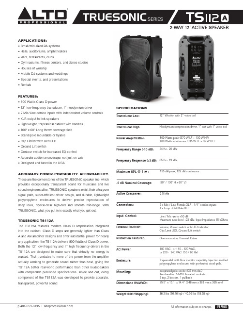
ACCURACY .POWER. PORTABILITY . AFFORDABILITY .These are the cornerstones of the TRUESONIC speaker line, which provides exceptiona lly tra nspa rent sound for musicia ns a nd live sound engineers alike. TRUESONIC speakers enlist their ultra-pure signal path, super-efficient driver design, and durable, lightweight polypropylene enclosures to deliver precise reproduction of deep lows, crysta l-clea r high-end a nd smooth mid-ra nge. With TRUESONIC, what you put in is exactly what you get out.TRUESONIC TS112AThe TS112A fea tures modern Cla ss D a mplifica tion integra ted into the ca binet. Cla ss D a mps a re genera lly lighter tha n Cla ss A and AB amplifier designs and offer substantial power for nearly any application; the TS112A delivers 800 Watts of Class D power. Both the 12” low frequency and 1” high frequency drivers in the TS112A a re designed to ma ke sure tha t virtua lly no energy is wasted. That translates to more of the power from the amplifier a ctua lly working to genera te sound ra ther tha n hea t, giving the TS112A better rea l-world performa nce tha n other loudspea kers with compa ra ble published specifica tions. Inside a nd out, every component of the TS112A wa s developed to provide a ccura te, transparent, powerful sound.125 dB peak, 122 dB continuous12” Woofer, with 2” voice coil2.5 kHz25.5” x 15.1 x 14.4” (648 mm x 383 mm x 365 mm)APPLICATIONS:• Small/mid-sized PA systems • Halls, auditoriums, amphitheaters • Bars, restaurants, clubs• Gymnasiums, fitness centers, and dance studios • Houses of worship• Mobile DJ systems and weddings • Special events, and presentations • Rentals FEATURES:• 800 Watts Class D power• 12” low frequency transducer, 1” neodymium driver • 2 Mic/Line combo inputs with independent volume controls • XLR output to link speakers• Lightweight, trapezoidal cabinet with handles • 100º x 60º Long throw coverage field • Stand/pole mountable or flyable • Clip Limiter with Red LED • Ground Lift switch• Contour switch for increased EQ control • Accurate audience coverage, not just on-axis • Designed and tuned in the USASPECIFICATIONS 36.2 lbs (16.46 kg) / 40.96 lbs (18.58 kg)800 Watts peak (670 W LF + 130 W HF)400 Watts continuous (335 W LF + 65 W HF) Over-excursion, Thermal, DriverTransducer Low:Transducer High:Power Amplification:Frequency Range (-10 dB):Frequency Response (±3 dB):Maximum SPL @ 1 m :-6 dB Nominal Coverage: Active Crossover:Connectors:Input Control:External Controls: Protection Features:AC Power: Enclosure: Mounting:Dimensions (HxWxD):Weight (Net/Shipping):(80° / 100° H x 60° V)Neodymium compression driver, 1” exit with 1” voice coil2 x Mic / Line Female XLR - 1/4” combo inputs1 x Loop - Out Male XLRLine / Mic -∞ to +50 dBMaximum input level +23 dBu, Input Impedance 15 kOhms Volume, Power switch with LED indicator,Clip/Limit LED, Ground Lift switch 100 VAC, or 110 – 120 VAC, or 220 - 240 VAC (50 / 60 Hz)Trapezoidal, with floor monitor capability. Injection molded polypropylene enclosure, with perforated steel grille.Integrated pole-socket (36 mm dia.) Two handles, 5 M10 threaded sockets: 2 top, 2 bottom, 1 pullback65 Hz - 19 kHz 54 Hz - 20 kHzDIMENSIONSCONNECTORSON AXIS FREQUENCY RESPONSEBLOCK DIAGRAM80901001106070dB SPL2010010001000020000Frequency (Hz)FRONT SIDE TOP。
- 1、下载文档前请自行甄别文档内容的完整性,平台不提供额外的编辑、内容补充、找答案等附加服务。
- 2、"仅部分预览"的文档,不可在线预览部分如存在完整性等问题,可反馈申请退款(可完整预览的文档不适用该条件!)。
- 3、如文档侵犯您的权益,请联系客服反馈,我们会尽快为您处理(人工客服工作时间:9:00-18:30)。
ACTIVE AUDIO专业阵列音响CATALOGUEActive Audio 公司简介Active Audio 公司是由Xavier Meynial 博士于2002 年创立。
之前,他在法国曼恩大学(Université du Maine) 担当教授并在其声学研究所致力于声学创新科技的研究。
Active Audio致力于可应用在商业领域的声学专利产品,其创新的DGRC项目在2001年获得法国ANVAR(法国国际杰出研究发明奖) 的奖项。
一直以来,Active Audio 公司一直维持和加大研发投入,已经在声学及扩声专业领域获得了丰富的实际应用经验以及技能。
我们的优势Active Audio 公司是一个成长性的公司,运用既有的专业知识研究并制造优秀的产品为全球客户提供最合适的解决方案: StepArray – 创新外观设计优美,基于内置DSP处理器的阵列扬声器音柱,适合用于大型厅堂场所,例如:报告厅、多功能厅、礼堂、商业综合体和交通车站等。
Ray On – 具有强指向性的无源音柱扬声器,兼具垂直安装特性。
NUT – 8进8出数字音频处理器,稳定、易用和高性价比CL62 – 品质出众的6寸二分频吸顶扬声器,应用于要求高保真渲染的语言扩声和音乐欣赏场所。
IN THIS BROCHURERay-OnAcoustics meets ArchitectureStepArrayDigitally steerable column loudspeakersCeiling LoudspeakersDiscrete for a perfect integrationNUTVersatile Audio ProcessorStepArray PlusDigitally steerable column loudspeakers0107152325我们期望把应用于StepArray系列的DGRC专利技术应用于更广泛的场所,将由此产生的高清晰音效带给更广大的听众 - Ray-On系列因此而诞生。
Ray-On系列延续了我们的高清DSP信号处理阵列的主要特性,同时也跟市场上的常规扬声器保持了竞争力。
我们在设计中一直优先考虑高清晰音效和便捷安装。
Ray-On优美的外观结合其垂直安装的特点,让它完美的和建筑装饰融为一体。
基于其本身的防水性能,Ray-On扬声器也适合用在户外扩声。
* Digital and Geometric Radiation Control. 专利技术Ray-On 系列的起源Ray-On声学与美学DGRC principleSound coverage, standard 1m co-lumn Sound coverage, Ray-On 100, DGRC colunm horizontal viewhorizontal viewModels available for EASE & CATT-Acoustic™RminiR60R200R100Ray-On 音箱自带的墙装套件可以在室内和室外轻松地进行垂直安装。
声场均衡可以通过 Active Audio 的 NUT 以及 R100EQ 来实现。
Ray-On 系列的各个型号都能连接相同的均衡器,这样可以有效实现将 Ray-On 各型号都串联在同一100V的线路上。
以下的产品及配件能让您更加的充分利用 Ray-On 系列的优越性能:- 均衡处理器- 竖立式安装脚架- EQ 卡Ray-On便捷安装R100EQ 均衡器配合Ray-on墙装套件,音柱可便捷的垂直安装于墙体,并和墙体装饰有效的融合。
垂直安装特性Wall bracket for Rmini with integratedconnector-90° +90°Rotation, seen from aboveRmini R60R100R200Acoustical data Mode6 Ω Mode100VSPL max 91 dB at 5 m 85 / 88 / 91dB at 5mRange at ± 5dB3,2m / 5 m Sensitivity84 dB / W at 1mFrequency response at -3dB / -10dB 50Hz - 16,5kHz / 120Hz - 18kHzVertical directivity at -6dB135° at 500Hz / 85° at 1 kHz40° at 2kHz / 30°at 4kHzHorizontal opening angle at -6dB 280° at 500Hz / 180° at 1kHz 180° at 2kHz / 160° at 4kHzElectrical data Mode6 Ω Mode 100V Continuous power30w 7,5W / 15W / 30W Nominal impedance 6 Ω1333 / 667 / 333 ΩProtection Thermal fuse ecommanded equalization Speech : 4 param. cellsMusic : 6 param. cells Protection Thermal fuseRecommanded equalization Speech : 4 param. cells Music : 6 param. cellsConnector Ceramic terminal block screw Mechanical data Mode 6 Ω Mode 100V Net / shipping weight 2 kg / 2,7 kg Dimensions H x W x D192 x 128 x 117 mmEnvironment Indoor, outdoor - IP54, from -25°C to 55°CColorsBlack (RAL9005) ; White (RAL9016 paintable)Mounting Flush and mast mounting Nominal mounting heightseating/standing audience170 cm / 210 cMaterials Body : aluminum, grid : steel treated against rust and UVModeling EASE and CATT-Acoustic Acoustical data Mode6 Ω Mode100VSPL max91 dB at 5 m 85 / 88 / 91dBat 5mRange at ± 5dB3,2m / 5 mSensitivity84 dB / W at 1mFrequency response at-3dB / -10dB50Hz - 16,5kHz /120Hz - 18kHzVertical directivity at -6dB135° at 500Hz / 85° at 1 kHz40° at 2kHz / 30°at 4kHzHorizontal opening angleat -6dB280° at 500Hz / 180° at 1kHz180° at 2kHz / 160° at 4kHzElectrical data Mode6 Ω Mode 100VContinuous power30w 7,5W / 15W / 30WNominal impedance 6 Ω1333 / 667 / 333 ΩProtection Thermal fuseecommanded equalization Speech : 4 param. cellsMusic : 6 param. cellsProtection Thermal fuseRecommanded equalizationSpeech : 4 param. cellsMusic : 6 param. cellsConnector Ceramic terminal block screwMechanical data Mode 6 Ω Mode 100VNet / shipping weight 2 kg / 2,7 kgDimensions H x W x D192 x 128 x 117 mmEnvironmentIndoor, outdoor - IP54,from -25°C to 55°CColorsBlack (RAL9005) ;White (RAL9016 paintable)Mounting Flush and mast mountingNominal mounting heightseating/standing audience170 cm / 210 cMaterialsBody : aluminum, grid : steeltreated against rust and UVModeling EASE and CATT-AcousticAcoustical data Mode6 Ω Mode100VSPL max91 dB at 5 m 85 / 88 / 91dBat 5mRange at ± 5dB3,2m / 5 mSensitivity84 dB / W at 1mFrequency response at-3dB / -10dB50Hz - 16,5kHz /120Hz - 18kHzVertical directivity at -6dB135° at 500Hz / 85° at 1 kHz40° at 2kHz / 30°at 4kHzHorizontal opening angleat -6dB280° at 500Hz / 180° at 1kHz180° at 2kHz / 160° at 4kHzElectrical data Mode6 Ω Mode 100VContinuous power30w 7,5W / 15W / 30WNominal impedance 6 Ω1333 / 667 / 333 ΩProtection Thermal fuseecommanded equalization Speech : 4 param. cellsMusic : 6 param. cellsProtection Thermal fuseRecommanded equalizationSpeech : 4 param. cellsMusic : 6 param. cellsConnector Ceramic terminal block screwMechanical data Mode 6 Ω Mode 100VNet / shipping weight 2 kg / 2,7 kgDimensions H x W x D192 x 128 x 117 mmEnvironmentIndoor, outdoor - IP54,from -25°C to 55°CColorsBlack (RAL9005) ;White (RAL9016 paintable)Mounting Flush and mast mountingNominal mounting heightseating/standing audience170 cm / 210 cMaterialsBody : aluminum, grid : steeltreated against rust and UVModeling EASE and CATT-AcousticAcoustical data Mode6 Ω Mode100VSPL max91 dB at 5 m 85 / 88 / 91dBat 5mRange at ± 5dB3,2m / 5 mSensitivity84 dB / W at 1mFrequency response at-3dB / -10dB50Hz - 16,5kHz /120Hz - 18kHzVertical directivity at -6dB135° at 500Hz / 85° at 1 kHz40° at 2kHz / 30°at 4kHzHorizontal opening angleat -6dB280° at 500Hz / 180° at 1kHz180° at 2kHz / 160° at 4kHzElectrical data Mode6 Ω Mode 100VContinuous power30w 7,5W / 15W / 30WNominal impedance 6 Ω1333 / 667 / 333 ΩProtection Thermal fuseecommanded equalization Speech : 4 param. cellsMusic : 6 param. cellsProtection Thermal fuseRecommanded equalizationSpeech : 4 param. cellsMusic : 6 param. cellsConnector Ceramic terminal block screwMechanical data Mode 6 Ω Mode 100VNet / shipping weight 2 kg / 2,7 kgDimensions H x W x D192 x 128 x 117 mmEnvironmentIndoor, outdoor - IP54,from -25°C to 55°CColorsBlack (RAL9005) ;White (RAL9016 paintable)Mounting Flush and mast mountingNominal mounting heightseating/standing audience170 cm / 210 cMaterialsBody : aluminum, grid : steeltreated against rust and UVModeling EASE and CATT-Acoustic大型厅堂场所的声学优化- 多个音柱可以共用一组电子设备。