80系列质量流量计的量程范围设置
流量计GFF80说明书
3.2 机械特性
3.2.1 通用特性 表3-2 通用特性对照表
被测介质 执行标准 检定规程 仪表口径及 连接方式 无杂质、低粘度、无强烈腐蚀性液体 涡轮流量传感器(JB/T9246-1999) 涡轮流量计(JJG1037-2008) 法兰连接型 DN15-DN200 螺纹连接型 夹装连接型 卡装连接型 常规标准 法兰标准*
H(mm) 脉冲 输出型 145 145 145 155 160 165 170 180 195 205 220 245 270 295 350 210 225 250 275 300 350 210 225 250 275 300 350 X 防爆脉冲 输出型 4-20mA 输出型 智能 显示型 215 215 215 220 225 230 240 245 260 275 290 310 340 365 415
6
GFF80系列液体涡轮流量计
四、安装注意事项
4.1 产品尺寸
4.1.1 螺纹连接型尺寸
表体 常规 订制
叶轮 常规 订制
前后导向 常规 订制
法兰或卡箍/卡盘 常规 304 碳钢 304 订制 316 304/316 -
304
316 2Cr13 双相钢
304
316
DN4-DN10 螺纹连接 传感器(含直管段)
H(mm)
仪表 口径 (mm) 4 6 10 15 20 25 32 40 50 65 80 100 125 150 200
L (mm) 50 50 50 55 60 60 70 70 70 80 90 100 120 150 150
D (mm) 38 38 38 47 53 58 66 72 92 100 112 137 165 190 243
恩德斯豪斯流量计80说明书

恩德斯豪斯流量计80说明书第一章:简介恩德斯豪斯流量计80是一种用于测量流体流量的仪器。
它采用先进的技术和设计,能够准确地测量各种液体的流量,并提供稳定的输出信号。
本说明书将介绍恩德斯豪斯流量计80的特点、使用方法和注意事项。
第二章:特点恩德斯豪斯流量计80具有以下特点:1. 高精度:采用先进的测量技术,能够实现高精度的流量测量。
2. 宽测量范围:适用于各种液体的流量测量,包括清洁液体和带有颗粒的液体。
3. 稳定性好:流量计具有良好的稳定性,能够在长时间使用中保持准确的测量结果。
4. 易于安装和维护:流量计采用便捷的接口和结构设计,方便用户进行安装和维护。
5. 多种输出方式:流量计支持多种输出方式,包括模拟信号输出和数字信号输出,方便与其他设备的连接和数据处理。
第三章:使用方法恩德斯豪斯流量计80的使用方法如下:1. 安装:根据实际情况选择合适的安装位置,并确保流量计与管道连接紧密,避免漏气和漏液。
2. 参数设置:根据实际需求,设置流量计的参数,包括单位、测量范围等。
3. 校准:在初次使用或者长时间使用后,需要对流量计进行校准,以确保测量结果的准确性。
4. 测量:打开流量计的开关,流体开始流动时,流量计将开始测量并输出相应的信号。
第四章:注意事项在使用恩德斯豪斯流量计80时,需要注意以下事项:1. 避免过大的流量冲击,以免损坏流量计。
2. 定期清洁和维护流量计,以确保其正常工作。
3. 避免流体中含有腐蚀性物质,以免对流量计造成损坏。
4. 注意保护流量计的接口和线缆,避免受到外界物体的损坏。
5. 根据需要选择适当的输出方式,并与其他设备进行连接。
第五章:常见问题解答1. 问:流量计的测量范围是多少?答:恩德斯豪斯流量计80的测量范围根据具体型号不同而有所差异,请参考产品说明书。
2. 问:流量计是否可以用于测量气体流量?答:恩德斯豪斯流量计80主要适用于液体流量的测量,不建议用于气体流量的测量。
3. 问:流量计的输出信号是什么形式的?答:流量计支持模拟信号输出和数字信号输出,具体形式可根据实际需求进行设置。
E+ H-Promass-80流量计基本操作步骤说明书
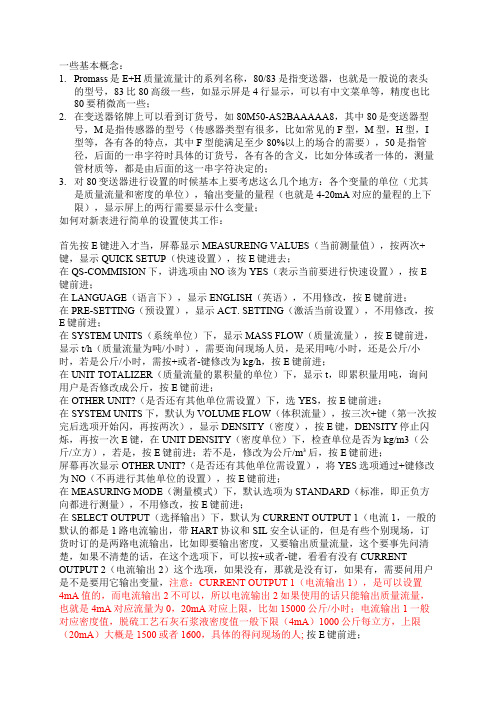
一些基本概念:1.Promass是E+H质量流量计的系列名称,80/83是指变送器,也就是一般说的表头的型号,83比80高级一些,如显示屏是4行显示,可以有中文菜单等,精度也比80要稍微高一些;2.在变送器铭牌上可以看到订货号,如80M50-AS2BAAAAA8,其中80是变送器型号,M是指传感器的型号(传感器类型有很多,比如常见的F型,M型,H型,I 型等,各有各的特点,其中F型能满足至少80%以上的场合的需要),50是指管径,后面的一串字符时具体的订货号,各有各的含义,比如分体或者一体的,测量管材质等,都是由后面的这一串字符决定的;3.对80变送器进行设置的时候基本上要考虑这么几个地方:各个变量的单位(尤其是质量流量和密度的单位),输出变量的量程(也就是4-20mA对应的量程的上下限),显示屏上的两行需要显示什么变量;如何对新表进行简单的设置使其工作:首先按E键进入才当,屏幕显示MEASUREING VALUES(当前测量值),按两次+键,显示QUICK SETUP(快速设置),按E键进去;在QS-COMMISION下,讲选项由NO该为YES(表示当前要进行快速设置),按E 键前进;在LANGUAGE(语言下),显示ENGLISH(英语),不用修改,按E键前进;在PRE-SETTING(预设置),显示ACT. SETTING(激活当前设置),不用修改,按E键前进;在SYSTEM UNITS(系统单位)下,显示MASS FLOW(质量流量),按E键前进,显示t/h(质量流量为吨/小时),需要询问现场人员,是采用吨/小时,还是公斤/小时,若是公斤/小时,需按+或者-键修改为kg/h,按E键前进;在UNIT TOTALIZER(质量流量的累积量的单位)下,显示t,即累积量用吨,询问用户是否修改成公斤,按E键前进;在OTHER UNIT?(是否还有其他单位需设置)下,选YES,按E键前进;在SYSTEM UNITS下,默认为VOLUME FLOW(体积流量),按三次+键(第一次按完后选项开始闪,再按两次),显示DENSITY(密度),按E键,DENSITY停止闪烁,再按一次E键,在UNIT DENSITY(密度单位)下,检查单位是否为kg/m3(公斤/立方),若是,按E键前进;若不是,修改为公斤/m³后,按E键前进;屏幕再次显示OTHER UNIT?(是否还有其他单位需设置),将YES选项通过+键修改为NO(不再进行其他单位的设置),按E键前进;在MEASURING MODE(测量模式)下,默认选项为STANDARD(标准,即正负方向都进行测量),不用修改,按E键前进;在SELECT OUTPUT(选择输出)下,默认为CURRENT OUTPUT 1(电流1,一般的默认的都是1路电流输出,带HART协议和SIL安全认证的,但是有些个别现场,订货时订的是两路电流输出,比如即要输出密度,又要输出质量流量,这个要事先问清楚,如果不清楚的话,在这个选项下,可以按+或者-键,看看有没有CURRENT OUTPUT 2(电流输出2)这个选项,如果没有,那就是没有订,如果有,需要问用户是不是要用它输出变量,注意:CURRENT OUTPUT 1(电流输出1),是可以设置4mA值的,而电流输出2不可以,所以电流输出2如果使用的话只能输出质量流量,也就是4mA对应流量为0,20mA对应上限,比如15000公斤/小时;电流输出1一般对应密度值,脱硫工艺石灰石浆液密度值一般下限(4mA)1000公斤每立方,上限(20mA)大概是1500或者1600,具体的得问现场的人;按E键前进;在ASSIGN CURRENT(分配电流输出),看默认选项是否是DENSITY(密度),如果是,按E键前进;如果不是,按+或者-键,找到DENSITY后,按E确定,并前进;在CURRENT SPAN(电流范围),默认选项为4-20ma HART NAM.,不用修改,按E 键前进;在VALUE 0_4mA下通过+或-键将密度的下限值(和现场人确定一下,一般是1000公斤/m³)输入,按E键前进;在VALUE 20mA下通过+或-键将密度的上限值(和现场人确定一下);按E键前进;在TIME CONSTANT(时间常数)下,默认是1秒,不管他,按E键前进;在FAILSAFE MODE(失效模式)下,默认是MIN. CURRENT(最小电流)不用管,按E键前进;在OTHER OUTPUT?(是否还有其他输出),这时候就要用到刚才说的,到底是有几路电流输出了,如果有电流输出2,这里选YES,在SELECT OUTPUT下,选CURRENT OUTPUT 2(电流输出2),ASSIGN CURRENT 下选MASS LOW(质量流量),VALUE 20ma下输入量程上限,即可,等输入完毕后还会返回OTHER OUTPUT(其他输出),选NO,即可;如果现场没有用2路电流,那在这里直接选NO,后面的直接按E键前进,提示BACK TO MENU后就跳回QS-COMMISION了,设置完成了,+和-键一起按,退到菜单;这时候,仪表已经能正常测量了,但是,屏幕显示还有修改一下,比如第一行显示密度值,第二行显示质量流量,或者第一行显示质量流量,第二行显示累积量什么的,需要问用户想怎么显示;在测量状态下,按E键进入菜单,显示MEASURING VALUES(当前测量值),按+号键,大概5,6次,显示USER INTERFACE(用户界面),按E键进入;在ASSIGN LINE 1(分配第一行显示内容)下,用+或-键找到用户想要的变量,变量选项里东西很多,可能会用到的有这么几个,具体用哪一个得问用户:DENSITY密度,TOTALIZER 1累积器1(就是质量流量的累积量),MASS FLOW质量流量,VOLUME FLOW体积流量,找到想要的东西以后按E键确定就可以了,这时候会提示ENTRY STORED(已经存储了修改),不用管他,就是一个提示,自己又会变成ASSIGN LINE 1(第一行显示变量,这时候对应的变量已经修改成你刚才选择的变量了),按E键前进,显示ASSIGN LINE 2(分配第二行的现实内容),和刚才第一样,问用户要显示什么,找到了以后按确定,然后显示FORMAT(格式,也就是几位小数)不用修改,按E键前进;DISPLAY DAMPING(显示阻尼),默认是5S,就是5秒,不用修改,按E键前进CONTRAST LCD(液晶屏对比度),不用修改,按E键前进;BACKLIGH(背光亮度),不用修改,按E键前进;TEST DISPLAY(是否测试显示),不用修改,按E键前进;会提示BACK TO MENU,然后自动返回菜单,此时设置完成,一起按+和-键推出就可以了;设置完成;。
E+H质量流量计调试演示教学

E+H质量流量计调试80系列质量流量计的的调试指导1.1分体式流量计接线传感器线侧接线图如下上侧为变送器表头腔室内接线,颜色对应如下:4-grey 灰色5-屏蔽6-green 绿色7-屏蔽8-yellow黄色+屏蔽9-pink粉红色10-屏蔽11-white 白色12-屏蔽41-对应线的标号142-对应线的标号2下侧为传感器侧接线腔室的接线对应关系同上。
电源/信号侧接线图:1和2为220伏电源,26(+)和27(-)为4-20毫安信号有源输出,四线制。
参数调试1、测量单位设置:在测量画面下,按“E”,进入主干菜单,按下“+”或者“-”,选择 SYSTEM UNIT (测量单位),按“E”进入,出现UNIT MASS FLOW(质量流量单位),按“+”或者“-”来选择单位为t/h,修改完成用“E”确认。
接着按E,然后找到,用+或者-修改为t。
初次修改选项时会弹出一个权限密码ACCESS CODE ,用“+”或者“-”输入密码80,按“E”确认密码并激活参数修改权限。
同时按+和-返回到主测量画面。
2、流量清零及其单位设置:在测量画面下,按“E”,进入主干菜单,按下“+”或者“-”,选择(累计),按“E”进入,出现(累计流量单位),按“+”或者“-”来选择单位为t,接着按E找到(累计模式),用+或者-修改为(正向累计)。
修改完成用“E”确认。
按E键进入(累计清零),用+或者-选择YES ,会弹出对话框Are you sure?,用+或者-选择YES后,按E 确认后,累积复位完成。
同时按+和-返回到主测量画面。
2、4-20毫安输出量程设置进入主菜单,按E后进入主菜单,按下“+”或者“-”,选择CURRENT OUTPUT ,按“E “进入,出现ASSIGNCURRENT ,按下“+”或者“-”选择。
按“E”确认并进入量程设置:CURRENT SPAN,选择4-20mA HART,按E确认后出现VALUE0-4mA,按“+”或者“-”输入下限量程。
E+H 质量流量计80F 80M技术说明书

TI067D/06/en 50108972Technical InformationProline Promass 84F, 84MCoriolis Mass Flow Measuring SystemThe universal and multivariable flowmeter for liquids and gasesfor custody transferApplicationsThe Coriolis measuring principle operates independently of the physical fluid properties, such as viscosity and density.•Extremely accurate, verified measurement of liquids (other than water) and for gases under high pressure (> 100 bar)•Fluid temperatures up to +200 °C •Process pressures up to 350 bar•Mass flow measurement up to 2200 t/h Approvals for custody transfer:•PTB, NMiApprovals for hazardous area:•ATEX, FM, CSA, TIISApprovals in the food industry/hygiene sector:•3A, FDAConnection to process control system:•HARTRelevant safety aspects:•Secondary containment (up to 100 bar), Pressure Equipment DirectiveFeatures and benefitsThe Promass measuring devices make it possible to simultaneously record several process variables (mass/density/temperature) for various process conditions during measuring operation.The Proline transmitter concept comprises:•Modular device and operating concept resulting in a higher degree of efficiency•Diagnostic ability and data back-up for increased process qualityThe Promass sensors, tried and tested in over 100000 applications, offer:•Multivariable flow measurement in compact design •Insensitivity to vibrations thanks to balanced two-tube measuring system•Efficient protection against forces from piping thanks to robust construction•Easy installation without taking inlet and outlet runs into accountProline Promass 84F, 84M2Endress+HauserTable of contentsFunction and system design. . . . . . . . . . . . . . . . . . . . .3Measuring principle . . . . . . . . . . . . . . . . . . . . . . . . . . . . . . . . . . . 3Measuring system . . . . . . . . . . . . . . . . . . . . . . . . . . . . . . . . . . . . . 4Input . . . . . . . . . . . . . . . . . . . . . . . . . . . . . . . . . . . . . .5Measured variable . . . . . . . . . . . . . . . . . . . . . . . . . . . . . . . . . . . . 5Measuring range in non-custody transfer mode . . . . . . . . . . . . . . . 5Measuring range in custody transfer mode . . . . . . . . . . . . . . . . . . 6Operable flow range . . . . . . . . . . . . . . . . . . . . . . . . . . . . . . . . . . . 6Input signal . . . . . . . . . . . . . . . . . . . . . . . . . . . . . . . . . . . . . . . . . 6Output. . . . . . . . . . . . . . . . . . . . . . . . . . . . . . . . . . . . .7Output signal . . . . . . . . . . . . . . . . . . . . . . . . . . . . . . . . . . . . . . . . 7Signal on alarm . . . . . . . . . . . . . . . . . . . . . . . . . . . . . . . . . . . . . . 7Load . . . . . . . . . . . . . . . . . . . . . . . . . . . . . . . . . . . . . . . . . . . . . . 7Low flow cut off . . . . . . . . . . . . . . . . . . . . . . . . . . . . . . . . . . . . . . 7Galvanic isolation . . . . . . . . . . . . . . . . . . . . . . . . . . . . . . . . . . . . . 7Power supply. . . . . . . . . . . . . . . . . . . . . . . . . . . . . . . .8Electrical connection Measuring unit . . . . . . . . . . . . . . . . . . . . . . 8Electrical connection, terminal assignment . . . . . . . . . . . . . . . . . . 9Electrical connection Remote version . . . . . . . . . . . . . . . . . . . . . . 9Supply voltage . . . . . . . . . . . . . . . . . . . . . . . . . . . . . . . . . . . . . . . 9Switching on the power supply in custody transfer mode . . . 9Cable entry . . . . . . . . . . . . . . . . . . . . . . . . . . . . . . . . . . . . . . . . . 9Cable specifications,remote version . . . . . . . . . . . . . . . . . . . . . . . . . . . . . . . . . . . . . . 9Power consumption . . . . . . . . . . . . . . . . . . . . . . . . . . . . . . . . . . 10Power supply failure . . . . . . . . . . . . . . . . . . . . . . . . . . . . . . . . . . 10Potential equalisation . . . . . . . . . . . . . . . . . . . . . . . . . . . . . . . . . 10Performance characteristics. . . . . . . . . . . . . . . . . . . .10Reference operating conditions . . . . . . . . . . . . . . . . . . . . . . . . . . 10Maximum measured error . . . . . . . . . . . . . . . . . . . . . . . . . . . . . 10Repeatability . . . . . . . . . . . . . . . . . . . . . . . . . . . . . . . . . . . . . . . . 12Influence of medium temperature . . . . . . . . . . . . . . . . . . . . . . . . 12Influence of medium pressure . . . . . . . . . . . . . . . . . . . . . . . . . . . 13Operating conditions: Installation . . . . . . . . . . . . . . .13Installation instructions . . . . . . . . . . . . . . . . . . . . . . . . . . . . . . . . 13Inlet and outlet runs . . . . . . . . . . . . . . . . . . . . . . . . . . . . . . . . . . 17Length of connecting cable . . . . . . . . . . . . . . . . . . . . . . . . . . . . . 17System pressure . . . . . . . . . . . . . . . . . . . . . . . . . . . . . . . . . . . . . 17Operating conditions: Environment. . . . . . . . . . . . . .18Ambient temperature range . . . . . . . . . . . . . . . . . . . . . . . . . . . . 18Storage temperature . . . . . . . . . . . . . . . . . . . . . . . . . . . . . . . . . . 18Degree of protection . . . . . . . . . . . . . . . . . . . . . . . . . . . . . . . . . . 18Shock resistance . . . . . . . . . . . . . . . . . . . . . . . . . . . . . . . . . . . . . 18Vibration resistance . . . . . . . . . . . . . . . . . . . . . . . . . . . . . . . . . . 18Electromagnetic compatibility (EMC) . . . . . . . . . . . . . . . . . . . . . 18Operating conditions: Process. . . . . . . . . . . . . . . . . .18Medium temperature range . . . . . . . . . . . . . . . . . . . . . . . . . . . . 18Medium pressure range (nominal pressure) . . . . . . . . . . . . . . . . 18Limiting flow . . . . . . . . . . . . . . . . . . . . . . . . . . . . . . . . . . . . . . . 19Pressure loss . . . . . . . . . . . . . . . . . . . . . . . . . . . . . . . . . . . . . . . 20Custody transfer measurement . . . . . . . . . . . . . . . . .22Custody transfer variables . . . . . . . . . . . . . . . . . . . . . . . . . . . . . 22 Suitability for custody transfer measurement, approval by the Standards Authorities, repeated calibration due to legal metrology controls . . . . . . . . . . . . . . . . . . . . . . . . . . . . . . . . . . . . . . . . . . 22Definition of terms . . . . . . . . . . . . . . . . . . . . . . . . . . . . . . . . . . . 22 Verification process . . . . . . . . . . . . . . . . . . . . . . . . . . . . . . . . . 23Stamp points . . . . . . . . . . . . . . . . . . . . . . . . . . . . . . . . . . . . . . . 24Mechanical construction . . . . . . . . . . . . . . . . . . . . . .25Design / dimensions . . . . . . . . . . . . . . . . . . . . . . . . . . . . . . . . . 25Weight . . . . . . . . . . . . . . . . . . . . . . . . . . . . . . . . . . . . . . . . . . . 53Material . . . . . . . . . . . . . . . . . . . . . . . . . . . . . . . . . . . . . . . . . . . 53Material load curves . . . . . . . . . . . . . . . . . . . . . . . . . . . . . . . . . . 55Process connections . . . . . . . . . . . . . . . . . . . . . . . . . . . . . . . . . . 60Human interface . . . . . . . . . . . . . . . . . . . . . . . . . . . .61Display elements . . . . . . . . . . . . . . . . . . . . . . . . . . . . . . . . . . . . 61Unified control concept for both types of transmitter: . . . . . . . . . 61Language groups . . . . . . . . . . . . . . . . . . . . . . . . . . . . . . . . . . . . 61Remote operation . . . . . . . . . . . . . . . . . . . . . . . . . . . . . . . . . . . . 61Certificates and approvals . . . . . . . . . . . . . . . . . . . . .61CE mark . . . . . . . . . . . . . . . . . . . . . . . . . . . . . . . . . . . . . . . . . . 61Ex approval . . . . . . . . . . . . . . . . . . . . . . . . . . . . . . . . . . . . . . . . 61Sanitary compatibility . . . . . . . . . . . . . . . . . . . . . . . . . . . . . . . . . 61Other standards and guidelines . . . . . . . . . . . . . . . . . . . . . . . . . . 61Pressure device approval . . . . . . . . . . . . . . . . . . . . . . . . . . . . . . 61Approval for custody transfer . . . . . . . . . . . . . . . . . . . . . . . . . . . 62Suitability for custody transfer measurement . . . . . . . . . . . . . . . . 62Ordering information. . . . . . . . . . . . . . . . . . . . . . . . .63Accessories . . . . . . . . . . . . . . . . . . . . . . . . . . . . . . . .63Documentation . . . . . . . . . . . . . . . . . . . . . . . . . . . . .63Registered trademarks. . . . . . . . . . . . . . . . . . . . . . . .63Proline Promass 84F, 84MEndress+Hauser 3Function and system designMeasuring principleThe measuring principle is based on the controlled generation of Coriolis forces. These forces are always present when both translational and rotational movements are superimposed.F C = 2 · ∆m (v · ω)F C = Coriolis force ∆m = moving mass ω = rotational velocityv = radial velocity in rotating or oscillating systemThe amplitude of the Coriolis force depends on the moving mass ∆m, its velocity v in the system, and thus on the mass flow. Instead of a constant angular velocity ω, the Promass sensor uses oscillation.In the Promass F and M sensors, two parallel measuring tubes containing flowing fluid oscillate in antiphase, acting like a tuning fork. The Coriolis forces produced at the measuring tubes cause a phase shift in the tube oscillations (see illustration):•At zero flow, in other words when the fluid is at a standstill, the two tubes oscillate in phase (1).The phase difference (A-B) increases with increasing mass flow. Electrodynamic sensors register the tube oscillations at the inlet and outlet.System balance is ensured by the antiphase oscillation of the two measuring tubes. The measuring principle operates independently of temperature, pressure, viscosity, conductivity and flow profile.Density measurementThe measuring tubes are continuously excited at their resonance frequency. A change in the mass and thus the density of the oscillating system (comprising measuring tubes and fluid) results in a corresponding, automatic adjustment in the oscillation frequency. Resonance frequency is thus a function of fluid density. The microprocessor utilises this relationship to obtain a density signal.Temperature measurementThe temperature of the measuring tubes is determined in order to calculate the compensation factor due to temperature effects. This signal corresponds to the process temperature and is also available as an output.The temperature measurement cannot be used to generate data for invoicing in applications subject to legal metrology controls.Proline Promass 84F, 84M Measuring system The measuring system consists of a transmitter and a sensor. Two versions are available:•Compact version: transmitter and sensor form a single mechanical unit.•Remote version: transmitter and sensor are installed separately.4Endress+HauserProline Promass 84F, 84MEndress+Hauser 5InputMeasured variable•Mass flow (proportional to the phase difference between two sensors mounted on the measuring tube to register a phase shift in the oscillation)•Fluid density (proportional to resonance frequency of the measuring tube)•Fluid temperature (measured with temperature sensors)Measuring range in non-custody transfer modeMeasuring ranges for liquids (Promass F, M):Measuring ranges for gasesThe full scale values depend on the density of the gas. Use the formula below to calculate the full scale values:g max(G) = g max(F) ⋅ ρ(G) / x [kg/m 3]g max(G) = Max. full scale value for gas [kg/h]g max(F) = Max. full scale value for liquid [kg/h]ρ(G) = Gas density in [kg/m 3] for process conditionsx = 160 (Promass F DN 8...100, M); x = 250 (Promass F DN 150...250)Here, g max(G) can never be greater than g max(F)Calculation example for gas:•Sensor type: Promass F, DN 50•Gas: air with a density of 60.3 kg/m 3 (at 20 °C and 50 bar)•Measuring range: 70000 kg/h •x = 160 (for Promass F DN 50)Max. possible full scale value:g max(G) = g max(F) ⋅ ρ(G) / x [kg/m 3] = 70000 kg/h ⋅60.3 kg/m 3 ÷ 160 kg/m 3 = 26400 kg/h Recommended full scale values See →Page 19ff. (“Limiting flow”)DN Range for full scale values (liquids) g min(F)...g max(F)80...2000 kg/h 150...6500 kg/h 250...18000 kg/h 400...45000 kg/h 500...70000 kg/h 800...180000 kg/h 100 (only Promass F)0...350000 kg/h 150 (only Promass F)0...800000 kg/h 250 (only Promass F)0...2200000 kg/hProline Promass 84F, 84M6Endress+HauserMeasuring range in custody transfer modeMeasuring ranges for liquids in mass flow (Promass F, M):Measuring ranges for liquids in volume flow (also LPG) (Promass F, M):Measuring ranges for high pressure fuel gases CNG (Promass M):Operable flow range Over 20 : 1 for verified device Input signalStatus input (auxiliary input):U = 3...30 V DC, R i = 5 k Ω, galvanically isolated.Configurable for: totalizer reset, positive zero return, error message reset, start zero point adjustmentDN Range for mass flow (liquids) Q min [kg/min]...Q max [kg/min]Smallest measured quantity[kg]8 1.5...300.515 5...10022515...30054035...700205050 (10005080)150...3000100100 (only Promass F)200...4500200150 (only Promass F)350...12000500250 (only Promass F)1500 (35000)1000DN Promass FDN Promass MRange for volume flow (liquids)(with P = 1 kg/dm 3)Q min [l/min]...Q max [l/min]Smallest measured quantity[l]88* 1.5...300.51515* 5...10022525*15...30054040*35...700205050*50 (1000508080)150...3000100100200...4500200150350 (12000500250)1500 (35000)1000* NMi approval onlyDNRange for mass flow (liquids)Q min [kg/min]...Q max [kg/min]Smallest measuredquantity [kg]Maximum pressure[bar]80.1...100.2160 / 350*150.3...400.5160 / 350*251.0 (100)2.0160 / 350** High pressure versionProline Promass 84F, 84MEndress+Hauser 7OutputOutput signalCurrent output:Active/passive selectable, galvanically isolated, time constant selectable (0.05...100 s), full scale value selectable, temperature coefficient: typically 0.005% o.r./°C, resolution: 0.5 µA •Active: 0/4...20 mA, R L < 700 Ω (for HART: R L ≥ 250 Ω)•Passive: 4...20 mA; supply voltage V S 18...30 V DC; R i ≥ 150 ΩPulse / frequency output:For custody transfer measurement, two pulse outputs can be operated, phase-shifted 90°.Passive, galvanically isolated, open collector, 30 V DC, 250 mA•Frequency output: full scale frequency 2...10000 Hz (f max = 12500 Hz), on/off ratio 1:1, pulse width max. 2 s. For phase-shifted double pulse max. 5000 Hz.•Pulse output: pulse value and pulse polarity selectable, pulse width configurable (0.05…2000 ms)Signal on alarmCurrent output:Failsafe mode selectable (for example, according to NAMUR recommendation NE 43)Pulse / frequency output:Failsafe mode selectableStatus output:De-energised by fault or power supply failureLoadSee “Output signal”Low flow cut offSwitch points for low flow cut off are selectable.Galvanic isolation All circuits for inputs, outputs, and power supply are galvanically isolated from each other.Nominal diameter Low flow cutoff / factory settings (v ∼ 0.04 m/s)[mm]SI units [kg/h]US units [lb/min]88.000.3001526.00 1.0002572.00 2.60040180.00 6.60050300.0011.00080720.0026.0001001200.0044.0001502600.0095.0002507200.00260.000Proline Promass 84F, 84M8Endress+HauserPower supplyElectrical connection Measuring unitConnecting the transmitter, cable cross-section: max. 2.5 mm2A View A (field housing)B View B (stainless steel field housing)C View C (wall-mount housing)aCable for power supply: 85...260 V AC, 20...55 V AC,16...62 V DC Terminal No. 1: L1 for AC, L+ for DC Terminal No. 2: N for AC, L- for DCb Signal cable: Terminals No. 20–27 →Page 9c Ground terminal for protective earth d Ground terminal for signal cable shielde Service connector for connecting service interface FXA 193 (FieldCheck, FieldTool)fCover of the connection compartmentProline Promass 84F, 84MEndress+Hauser9Electrical connection, terminal assignmentPromass 84Replacements for modules which are defective or which have to be replaced can be ordered as accessories.Electrical connection Remote versionSupply voltage85...260 V AC, 45...65 Hz 20...55 V AC, 45...65 Hz 16...62 V DCSwitching on the power supply in custody transfer modeIf the device is started in custody transfer mode, for example also after a power outage, system error No. 271 “POWER BRK. DOWN” flashes on the local display. The fault message can be acknowledged or reset using the "Enter" key or by means of the status input configured accordingly.!Note!For correct measuring operation, it is not mandatory to reset the fault message.Cable entryPower supply and signal cables (inputs/outputs):•Cable entry M20 x 1.5 (8...12 mm)•Threads for cable entries, 1/2" NPT, G 1/2"Connecting cable for remote version:•Cable entry M20 x 1.5 (8...12 mm)•Threads for cable entries, 1/2" NPT, G 1/2"Cable specifications,remote version•6 x 0.38 mm 2 PVC cable with common shield and individually shielded cores •Conductor resistance: ≤ 50 Ω/km •Capacitance core/shield: ≤ 420 pF/m •Cable length: max. 20 m•Permanent operating temperature: max. +105 °COperation in zones of severe electrical interference:The measuring device complies with the general safety requirements in accordance with EN 61010, the EMC requirements of EN 61326/A1, and NAMUR recommendation NE 21/43.Terminal No. (inputs/outputs)Order variant 20 (+) / 21 (-)22 (+) / 23 (-)24 (+) / 25 (-)26 (+) / 27 (-)84***-***********MStatus inputFrequency output 2Frequency output 1Current output HARTProline Promass 84F, 84M10Endress+HauserPower consumptionAC: <15 VA (including sensor)DC: <15 W (including sensor)Switch-on current•max. 13.5 A (< 50 ms) at 24 V DC •max. 3 A (< 5 ms) at 260 V ACPower supply failureLasting min. 1 power cycle:•EEPROM or HistoROM T-DAT saves measuring system data if power supply fails.•HistoROM/S-DAT: exchangeable data storage chip which stores the data of the sensor (nominal diameter, serial number, calibration factor, zero point, etc.)•See Note on Page 9 (switching on the power supply in custody transfer mode)Potential equalisationNo measures necessary.Exception: explosion protected equipment must be included in the potential equalization.Performance characteristics!Note!The accuracy solely refers to the measuring device suitable for custody transfer measurement and not to the measuring system.Reference operating conditionsError limits following ISO/DIS 11631:•20...30 °C; 2...4 bar•Calibration systems as per national norms•Zero point calibrated under operating conditions•Field density calibrated (or special density calibration)Maximum measured errorThe following values refer to the pulse/frequency output. Deviation at the current output is typically ±5 µA.Mass flow (liquid):±0.10% ± [(zero point stability / measured value) x 100]% o.r.Mass flow (gas):Promass F:±0.35% ± [(zero point stability / measured value) x 100]% o.r.Promass M:±0.50% ± [(zero point stability / measured value) x 100]% o.r.Volume flow (liquid)Promass F:±0.15% ± [(zero point stability / measured value) x 100]% o.r.Promass M:±0.25% ± [(zero point stability / measured value) x 100]% o.r.o.r. = of readingZero point stability (Promass F, M):Sample calculationMaximum measured error in % of reading (example: Promass 84 F / DN 25)Calculation example (mass flow, liquid):Given: Promass 84 F / DN 25, measured value flow = 8000 kg/hMax. measured error: ±0.10% ± [(zero point stability / measured value) x 100]% o.r.Maximum measured error → ±0.10% ±0.54 kg/h ÷ 8000 kg/h ⋅ 100% = ±0.107%Density (liquid)Standard calibration (1g/cc = 1 kg/l):Promass F ±0.01 g/cc Promass M ±0.02 g/ccDNMax. full scale value [kg/h] or [l/h]Zero point stabilityPromass F [kg/h] or [l/h]Promass M [kg/h] or [l/h]820000.0600.1001565000.2000.32525180000.5400.904045000 2.25 2.255070000 3.50 3.50801800009.009.0010035000014.00−150********.00−250220000088.00−Special density calibration (optional), not for high temperature versionPromass F±0.001 g/ccPromass M±0.002 g/ccAfter field density calibration or under reference conditions:Promass F±0.0005 g/ccPromass M±0.0010 g/ccTemperaturePromass F, M:±0.5 °C ±0.005 x T (T = fluid temperature in °C)Repeatability Mass flow (liquid):±0.05% ± [1/2 x (zero point stability / measured value) x 100]% o.r.Mass flow (gas):±0.25% ± [1/2 x (zero point stability / measured value) x 100]% o.r.Volume flow (liquid):Promass F:±0.05% ± [1/2 x (zero point stability / measured value) x 100]% o.r.Promass M:±0.10% ± [1/2 x (zero point stability / measured value) x 100]% o.r.o.r. = of readingZero point stability: see “Max. measured error”Calculation example (mass flow, liquid):Given: Promass 84 F / DN 25, measured value flow = 8000 kg/hRepeatability: ±0.05% ± [(1/2 x zero point stability / measured value) x 100]% o.r.Repeatability → ±0.05% ±1/2 ⋅ 0.54 kg/h ÷ 8000 kg/h ⋅ 100% = ±0.053%Density measurement (liquid)Promass F:±0.00025 g/cc (1 g/cc = 1 kg/l)Promass M:±0.0005 g/ccTemperature measurement±0.25 °C ±0.0025 x T (T = fluid temperature in °C)Influence of medium temperature When there is a difference between the temperature for zero point adjustment and the process temperature, the typical measured error of the Promass sensor is ±0.0002% of the full scale value / °C.Influence of medium pressureThe table below shows the effect on accuracy of mass flow due to a difference between calibration pressure and process pressure.Operating conditions: InstallationInstallation instructionsNote the following points:•No special measures such as supports are necessary. External forces are absorbed by the construction of the instrument, for example the secondary containment.•The high oscillation frequency of the measuring tubes ensures that the correct operation of the measuring system is not influenced by pipe vibrations.•No special precautions need to be taken for fittings which create turbulence (valves, elbows, T-pieces, etc.), as long as no cavitation occurs.•For mechanical reasons and in order to protect the pipe, it is advisable to support heavy sensors.•Please refer to the verification ordinances for the installation conditions of the approval for custody transfer in question.!Note!The necessary steps for creating a measuring system and obtaining approval from the Standards Authorities must be clarified with the authority for legal metrology controls responsible.Mounting locationEntrained air or gas bubbles in the measuring tube can result in an increase in measuring errors Avoid the following locations:•Highest point of a pipeline. Risk of air accumulating.•Directly upstream of a free pipe outlet in a vertical pipeline.Mounting locationDN Promass F [% o.r./bar]Promass M [% o.r./bar]Promass M / (high pressure)[% o.r./bar]8No influence 0.0090.00615No influence 0.0080.00525No influence 0.0090.00340-0.0030.005-50-0.008No influence -80-0.009No influence−100-0.012−−150-0.009−−250-0.009−−o.r. = of readingThe proposed configuration in the following diagram, however, permits installation in a vertical pipeline. Pipe restrictors or the use of an orifice plate with a smaller cross-section than the nominal diameter prevent the sensor from running empty during measurement.Installation in a vertical pipe (e.g. for batching applications)1Supply tank2Sensor3Orifice plate, pipe restrictions (see Table)4Valve5Batching tankDN815254*********)1501)2501)∅ Orifice plate, pipe6 mm10 mm14 mm22 mm28 mm50 mm65 mm90 mm150 mm restriction1) only Promass FOrientationMake sure that the direction of the arrow on the nameplate of the sensor matches the direction of flow (direction in which the fluid flows through the pipe).VerticalRecommended orientation with upward direction of flow (View V). When fluid is not flowing, entrained solids will sink down and gases will rise away from the measuring tube. The measuring tubes can be completely drained and protected against solids build-up.HorizontalThe measuring tubes must be horizontal and beside each other. When installation is correct the transmitter housing is above or below the pipe (View H1/H2). Always avoid having the transmitter housing in the same horizontal plane as the pipe.Please note the special installation instructions! see Page16In order to ensure that the maximum permissible ambient temperature for the transmitter (–20...+60 °C, optional –40...+60 °C) is not exceeded, we recommend the following orientations:m = For fluids with low temperatures, we recommend the horizontal orientation with the transmitter head pointing upwards (Fig. H1) or the vertical orientation (Fig. V).n = For fluids with high temperatures, we recommend the horizontal orientation with the transmitter head pointing downwards (Fig. H2) or the vertical orientation (Fig. V).Special installation instructions for Promass F"Caution!The two measuring tubes for Promass F are slightly curved. The position of the sensor, therefore, has to be matched to the fluid properties when the sensor is installed horizontally .Promass F, installed horizontally1Not suitable for fluids with entrained solids. Risk of solids accumulating.2Not suitable for outgassing fluids. Risk of air accumulating.HeatingSome fluids require suitable measures to avoid loss of heat at the sensor. Heating can be electric, e.g. with heated elements, or by means of hot water or steam pipes made of copper. "Caution!•Risk of electronics overheating! Consequently, make sure that the adapter between the sensor andtransmitter and the connection housing of the remote version always remain free of insulating material. Note that a certain orientation might be required, depending on the fluid temperature see Page15.•When using electrical heat tracing whose heat is regulated using phase control or by pulse packs, it cannot be ruled out that the measured values are influenced by magnetic fields which may occur, (i.e. at valuesgreater than those permitted by the EC standard (Sinus 30 A/m)). In such cases, the sensor must bemagnetically screened (except for Promass M).The secondary containment can be shielded with tin plates or electric sheets without privileged direction(e.g. V330-35A) with the following properties:–Relative magnetic permeability µr≥ 300–Plate thickness d ≥ 0.35 mm•Information on permissible temperature ranges →Page18Special heating jackets which can be ordered as accessories from Endress+Hauser are available for the sensors.Thermal insulationSome fluids require suitable measures to avoid loss of heat at the sensor. A wide range of materials can be used to provide the required thermal insulation.Zero point adjustmentAll Promass measuring devices are calibrated with state-of-the-art technology. The zero point determined inthis way is imprinted on the nameplate. Calibration takes place under reference operating conditions.→Page10ff.Consequently, the zero point adjustment is generally not necessary for Promass!Experience shows that the zero point adjustment is advisable only in special cases:•To achieve highest measuring accuracy also with very small flow rates.•Under extreme process or operating conditions (e.g. very high process temperatures or very high viscosityfluids).Note the following before you perform a zero point adjustment:•A zero point adjustment can be performed only with fluids that contain no gas or solid contents.•Zero point adjustment is performed with the measuring tubes completely filled and at zero flow(v = 0 m/s). This can be achieved, for example, with shut-off valves upstream and/or downstream of thesensor or by using existing valves and gates.–Normal operation → valves 1 and 2 open–Zero point adjustment with pump pressure → Valve 1 open / valve 2 closed–Zero point adjustment without pump pressure → Valve 1 closed / valve 2 openZero point adjustment and shut-off valvesInlet and outlet runs There are no installation requirements regarding inlet and outlet runs.Length of connecting cable Max. 20 meters (remote version)System pressure It is important to ensure that cavitation does not occur, because it would influence the oscillation of themeasuring tube. No special measures need to be taken for fluids which have properties similar to water undernormal conditions.In the case of liquids with a low boiling point (hydrocarbons, solvents, liquefied gases) or in suction lines, it isimportant to ensure that pressure does not drop below the vapour pressure and that the liquid does not startto boil. It is also important to ensure that the gases that occur naturally in many liquids do not outgas. Sucheffects can be prevented when system pressure is sufficiently high.Consequently, it is generally best to install the sensor:•downstream from pumps (no danger of vacuum),•at the lowest point in a vertical pipe.。
E+H 80质量流量计调试

80系列质量流量计的的调试指导1.1分体式流量计接线传感器线侧接线图如下上侧为变送器表头腔室内接线,颜色对应如下:4-grey 灰色5-屏蔽6-green 绿色7-屏蔽8-yellow黄色+屏蔽9-pink粉红色10-屏蔽11-white 白色12-屏蔽41-对应线的标号142-对应线的标号2下侧为传感器侧接线腔室的接线对应关系同上。
电源/信号侧接线图:1和2为220伏电源,26(+)和27(-)为4-20毫安信号有源输出,四线制。
参数调试1、测量单位设置:在测量画面下,按“E”,进入主干菜单,按下“+”或者“-”,选择SYSTEM UNIT (测量单位),按“E”进入,出现UNIT MASS FLOW(质量流量单位),按“+”或者“-”来选择单位为t/h,修改完成用“E”确认。
接着按E,然后找到,用+或者-修改为t。
初次修改选项时会弹出一个权限密码ACCESS CODE ,用“+”或者“-”输入密码80,按“E”确认密码并激活参数修改权限。
同时按+和-返回到主测量画面。
2、流量清零及其单位设置:在测量画面下,按“E”,进入主干菜单,按下“+”或者“-”,选择(累计),按“E”进入,出现(累计流量单位),按“+”或者“-”来选择单位为t,接着按E找到(累计模式),用+或者-修改为(正向累计)。
修改完成用“E”确认。
按E键进入(累计清零),用+或者-选择YES ,会弹出对话框Are you sure?,用+或者-选择YES后,按E 确认后,累积复位完成。
同时按+和-返回到主测量画面。
2、4-20毫安输出量程设置进入主菜单,按E后进入主菜单,按下“+”或者“-”,选择CURRENT OUTPUT ,按“E“进入,出现ASSIGNCURRENT ,按下“+”或者“-”选择。
按“E”确认并进入量程设置:CURRENT SPAN,选择4-20mA HART,按E确认后出现V ALUE0-4mA,按“+”或者“-”输入下限量程。
80质量流量计操作

注意,需要输入密码时,输入80即可。
1、按“E”进入“GROUP SELECT”(主菜单),按“+”找到“system units(系统单位)”,按“E”进入,此时,画面显示为“unit mass flow”(这是质量流量的单位),按“+”和“—”进行设置,按“E”键确定存储。
设定完以后,同时按“+”“—”返回总菜单2、从主菜单,按“+”找到“user interface (用户界面)”,按“E”进入,显示为“assigne line 1(第一行显示变量)”,按“+”找到“mass flow”(质量流量),按“E”确认并返回主菜单。
3、从主菜单,按“+”找到“current output 1(电流输出)”按“E”进入,画面显示为“assign current”(定义输出电流),按“+”找到“mass flow”(质量流量),按“E”确认,再次按“E”,画面显示为“current span”(电流范围),按“+”选择“4-20mA hart nam”,按“E”确认,显示画面为“value 0_4mA”输入0-4mA 对应值,按“E”确认进入下一子菜单(4mA设置这个菜单可能没有,新系统默认为0流量对应4mA),此时,显示画面为“value 20mA”,输入20mA对应值,按“E”确认并保存,返回主菜单。
4、从主菜单,按“+”找到“processparameter (过程参数)”按“E”进入,画面为“assigne lf-cut off(小流量切除)”,按“+”找到“mass flow(质量流量)”按“E”确定,再次按“E”,进入“on-val。
Lf-cutoff”,输入数值(此数值为总流量的3~5%),按“E”保存以下为仪表测量出现误差时,服务人员的操作,用户在进行新表调试时,不需要操作。
5、按E进入主菜单后,查找PROCESS PARAMETER(过程参数),翻页找到ZEROADJUSTMENT(零点调整),按E进入。
质量流量计技术参数
质量流量计技术参数一、质量流量计的概述质量流量计是一种测量介质实际通过管道的质量流量的仪器,它不仅可以测量气体,还可以测量液体。
相比于传统的体积流量计,它可以避免由于密度变化而引起的误差,具有更高的精度和可靠性。
二、工作原理质量流量计主要由传感器和信号转换器两部分组成。
传感器通常采用热式或冷式传感器,通过测量介质通过管道时产生的温度变化来计算出介质的实际质量流量。
信号转换器则将传感器采集到的信号进行放大、滤波等处理,并将结果输出为标准信号,以供后续处理或显示。
三、技术参数1. 测量范围:一般来说,质量流量计的测量范围比较广泛,从几毫克/小时到数千吨/小时都有可能。
需要根据具体应用场景选择合适的测量范围。
2. 精度:精度是衡量一个仪器好坏的重要指标之一。
对于质量流量计而言,其精度通常在0.1%~1%之间,具体取决于传感器的精度以及信号转换器的性能。
3. 响应时间:响应时间是指仪器从接收到输入信号到输出稳定的时间。
对于质量流量计而言,响应时间一般在几十毫秒到几秒之间,需要根据具体需求选择合适的响应时间。
4. 环境温度范围:质量流量计通常需要在一定的环境温度范围内工作,一般来说,其工作温度范围为-40℃~+80℃左右。
5. 输出信号:质量流量计通常可以输出多种信号类型,包括模拟信号和数字信号。
其中模拟信号可以是电压、电流或频率等形式,数字信号则可以是RS485、HART等协议。
四、选型建议选择合适的质量流量计需要考虑多个因素,包括测量介质、测量范围、精度要求、环境条件等。
在实际选型过程中,需要根据具体需求进行综合考虑,并选择性价比最高的产品。
同时,在安装和使用过程中也需要注意保养和维护,以确保其长期稳定运行。