(工艺技术)FRNC5PC工艺计算软件中文操作指南
INPHO DTMaster中文操作手册

北京超图软件股份有限公司 2012 年 2 月
教程 ..................................................................................................................................................4 案例学习:...............................................................................................................................5 A 浮动的窗口界面 ..........................................................................................................5 B 处理较大数据-稀疏模式 .............................................................5 C 捕获点/线 .....................................................................................................................6 D 用“Create Point List” 捕捉数据.................................................................................7 E 用“Add Point List” 捕捉数据........................................................................................9 F 用侧视图编辑雷达数据...........................................................................................10 G 编辑 MATCH-T数据 ................................................................................................10 H 导入矢量数据——DXF例子 ......................................................................................12 I 导出矢量数据——分开导出DXF................................................................................13 J 过滤器 .........................................................................................................................14 K 检查工程-线交叉 .......................................................................................................18
1加热炉工艺计算软件FRNC5使用入门
1加热炉工艺计算软件FRNC5使用入门通用加热炉工艺计算软件FRNC-5使用入门FRNC-5软件的引进与使用概况中石化集团公司下属的若干设计院(石化工程公司)从1997年开始引进了多套美国PFR公司的通用加热炉工艺计算软件FRNC-5。
此软件在加热炉工艺计算中得到很好的应用,发挥了重大作用。
美国PFR公司全称为PFR工程系统公司(PFR Engineering System,Inc )。
公司设在美国洛杉矶,创建于1972年1月,从事热力学系统设计分析和人员培训。
该公司的软件产品拥有六十多个用户,遍布六大洲的十五个以上的国家。
其中FRNC-5PC软件有二十年以上的使用经验。
本软件可以优化加热炉设计,并可对现有加热炉进行操作分析、加强管理,是一个较为优秀的软件。
FRNC-5软件功能与特点2.1 软件应用范围本程序可用于炼油、石油化工及热电联合等装置中大多数火焰加热炉及水管锅炉的性能模拟及效率预测。
程序采用经过证明了的技术,通过综合迭代,将工艺物流模拟、传热和压力降计算等过程组合在一起。
程序沿物流及烟气流程,逐个管组逐个炉段严格迭代求解,能精确确定加热炉的工艺参数。
计算中还指明不利操作状态,如发出炉膛正压、管壁和扩面元件超温、超临界流动以及酸露点腐蚀等警告信息。
程序会算出与显示加热炉的以下工艺参数或不利操作状态:(1)加热炉总热负荷、总热效率,辐射室热负荷(2)辐射室出口温度(桥墙温度)与烟囱入口处温度(3)辐射和对流热强度的均值和峰值(4)辐射段遮蔽段和对流段中所有管组的管壁金属温度和翅片尖端温度的峰值和均值(5)两相流流型及沸腾状态的确定(6)管内两相流的传热和压降(7)管外传热和阻力(8)“阻塞”、“干锅”或“冷端”腐蚀的可能性2.2 适用的加热炉类型(1)常减压装置加热炉(2)铂重整、铂铼重整和强化重整等装置加热炉(3)重沸炉和过热炉(4)一氧化碳加热炉和锅炉(5)脱硫装置原料预热炉(6)焦化炉和减粘加热炉(7)润滑油蒸馏和蜡油加热炉(8)煤炭液化加热炉(9)螺旋管加热炉(10)蒸汽发生器(11)余热锅炉本软件不适用于制氢、合成氨、甲醇等工艺装置的转化炉。
新墨菲解决方案:工艺师说明书

Newfangled Solutions Mill WizardThe Mill Wizard is a set of helpful tools to generate G code for common milling jobs.TO START USING THE WIZARD, READ THE HELP FILE AND SET THE CONFIG SETTINGS appropriately for your machine.The Mill Wizard is very job oriented, it has the ability to combine one or more operations to create a complete G code program for a complex part. As you build the job you may go back and edit, delete, or move up or down operations in the job list. You may save and re-load a job file which can serve as a template for future jobs.All data entered for an operation is stored in an ini file. When you return to an operation, the previous values will be displayed. This is handy if you only want to make a small change and re-use the operation. An example is making a finish pass on a circular pocket. The first run would use a diameter just slightly undersize, then run the same operation again with the final diameter entered.All milling screens provide several Z values to control the depth of cut.Drill cycles Retract refers to the height the drill will return after each step/peck. The drill cycles retract distance will be equal to the Clearance. In some G code documentation, this may be refered to as Rapid. Rapid should refer to the height at which XYmoves are allowed, above all surfaces, whether it is material top, clamps or holding fixtures.These values will be saved in the wizards .ini file, and will be compared to the calculated values in theMaterialThe Mill Wizard includes a material table with surface feed rates for a variety of materials and tool types. The table is preloaded with common values, but a user will need to modify the table for their particular needs. The values in this table will be used by the tool select dialog to calculate a spindle speed (RPM) and a feed rate.The Config menu on the top menu bar provides an option to open the material table.The screen will open with a display of the current table. You may delete or edit any of the cells as required. When you are finished simply click the Save button and the file wil be saved.Surface speed values must be entered in Inch units- Feet per minute- even if your jobs are metric. The program will calculate metric values when needed.The feed rate will be calculated based on a chip load factor. The chip load factor is normally calculated to be 10% of the tool diameter for tools less than 1" (25.4mm) in diameter. For tools larger than 1" (25.4mm) the chip load will be set to .010 inch (2.54mm). For HSS tools this chip load is reduced by a factor of 0.33.Each material may specify a % over ride value for feed calculations. For example, if you want to mill a soft material like aluminum 50% faster, set the % Feed value to 1.5. If you use a very hard material. you might want to reduce the feed rate by using .50 for a 50% reduction.Plunging moves are usually made at a slower rate than feed moves. The wizard wil first calculae a feed rate as explained above, then the Plunge rate will be adjusted by the %Plunge value in this table. A plunge rate of 50% is commonly used. You may set the rate to any value you choose.DisplayThe display colors can be changed by selecting Config, Tool Path Colors, on the main screen.Tool TableThe Newfangled Mill Wizard includes a tool table which is used in coordination with the material table to calculate the appropriate feed speeds, tool path, and resulting code for operating your mill. % Overrides for the calculated tool speeds are located in the Material Table.The table contains the tool diameter, number of flutes, Type, ramp angle and a description. This information will be automatically inserted into the New tool dialog simply by selecting the tool from the drop down list.The tool table edit screen can be openned through the main menu by selecting: Config, Tool Table.You may have up to 128 tools. It is not necessary that all entries are used. For example, tool #2 could be left blank.The tool table can be saved into a simple text file, where the fields are separated by the | character.License ManagementThe Newfangled Mill Wizard is licensed for full use. The program may be downloaded from the web and run in demo mode without a license. In demo mode all operations are functional exept Save Gcode and Show Gcode.The license is linked to a specific PC, requiring a different code for each PC. Use the About Box to get the PC code.To obtain your license key connect to the web site and follow the link to purchase a license. You will need to supply some personal ID information and the contents of the PC ID box as shown above. Click the 'copy ID to Clipboard' button and paste this ID number in the appropriate location on the website when purchasing your license.You will receive an e-mail with an attached license file. You may also want to make a backup copy of this license file in a safe place.IMPORTANT NOTE: The LICENSE will only work for the Computer for which you supplied the PC ID. Each PC has a unique ID code and the license works in coordination with this code.*******************************************************************************************************.The current list of operations will be displayed in the list box on the left side of the main screen. By selecting an item on the list it may be moved up or down in the list by clicking the arrows to the right of the list. The right click also allows Edit, delete or copy. Copy will make a copy of the selected operation and add it to the list directly below the selected item. This is useful in several1. A material must be selected from the list of materials displayed. This allows the tool select screen to calculate theappropriate spindle RPM and feed rate.A ToolTable is provided and shown in the top drop down box. If a tool is selected from the table it will automaticaly fill the tool diameter, units, flutes, tool type and ramp angle fields. You may change the fields as you need. The tool table is a starting point for quickly filling the required fields.This buton will display a screen showing all the current gcode produced for this job. Note this button will be disabled when running in demo mode. Please license your copy of the Newfangled Mill Wizard.This button will verify if you want to save the file. When selecting 'yes' an M9 and M30 will be written at the end of the file and the file saved to the selected location.This operation will surface the top of stock. The cutter will start off the edge of the stock and end off the edge by exactly one tool diameter.Cuts wil always be along the X direction.The origin selection determines which corner, or the center, of the part should be used as the origin point. The origin symbol appears in the selected position.Length is measured along the X axis, width along the Y axis.A corner radius may be specified. If the radius is Zero an outside cut will have square corners. An inside cut will always have at least a tool radius in the corners.The rectangle is defined by an X and Y pair and an origin setting that determines a starting corner, or the center, of the rectangle.The cut will ramp down in the Z direction as determined by the ramp angle set in the Tool arc along the line of the cut.See Cutting strategies for an explanation of the depth of cut. The X and Y origin entries determine the start point of the slot.See Cutting stragegies for an explanation of the depth of cut.Angles are referenced to zero degrees at the 3:00 o'clock position, with positive values going counter clockwise.The text start point refers to the lower left hand corner of a box surrounding the first character of the text. Character widths vary as appropriate for each character - an "I" will be in a box less wide than a "W". All letters are the same height. The text size is controlled by entering the text height. The text length box is displayed to indicate the approximate length required for the enteredThread MillThe wizard can generate code for thread milling operations.This operation wil generate a single pass cut for the specified thread configuration.If using metric units enter the thread pitch in mm. If English units enter the number of threads per inch.The rectangular pocket is defined by an X and Y pair and an origin setting that determines a starting corner, or the center, of the rectangle. The Length is measured in the X direction, the width is measured in the Y direction.The cut will begin along a centerline of the pocket and proceed in an outward pattern of increasing size rectangles.The circular pocket will begin in the center of the circle and make a helical ramp down with the ramp angle specified in the Dialog.Effective tool diameter is the actual diameter multipled by the % step over value. Step over values greater than 50% may leaveThis operation will drill as many holes as needed along a circle. The circle is specified by an XY value for the center and the diameter of the circle.The first hole of the circle will be at the 0 degree, or max positive X value, unless a starting angle is specified.This operation will drill a series of evenly spaced holes along a straight line. The line is specified by an XY value for the start of the line and an angle.The number of holes is specified and the increment between the holes.This operation will create a rectangular array of holes. The array is specified by an XY pair for a starting corner, an origin selection, and a length and width.The starting origin may be any of the four corners or the center of the rectangle.This operation will drill holes at a list of XY pairs. The list may be entered into the table manually or specified in a file of comma separated values (commonly called a CSV file). This file may be generated by using many different software programs.You can also enter values directly into the grid control. If more than 20 holes are needed, another list of holes operation can be run with the remaining coordinates.SplineSpline cutting requires a 4th axis that can be arranged to support a shaft that is to be splined. The spline is cut by a flat bottom end mill.The Y zero must be set so the tool is exactly centered over the center of the shaft.Z zero is set with the tool exactly at the top surface of the shaft. The diameter of the shaft is not needed.Note: the X cut direction may be in either direction by setting Xstart and Xend appropriately.The first cut will ramp from the surface to full depth, then reverse over the same path to clear the ramp.The Gcode will be generated as one file without using a subroutine. This makes it easier to handle the code, but makes the code longer than using subroutines.There are 4 possible setups for gear cutting. The blank may be in front or in back of the tool, and it may cut from left to right, or reverse. The Setup box is used to select the desired setting.。
CAXA V5 CAPP软件介绍2007V1.0

CAXA V5 CAPP ——工艺BOM管理
实现与设计数据的集成 导入产品设计的EBOM; 对EBOM进行调整转化为工艺BOM; 实现不同产品或同一产品不同BOM视图 之间的对比; 可以浏览产品、零件的设计图纸;
企业收益:
1.减少工艺人员的重复输入, 提供工艺编制效率; 2.提供工艺管理的基础
联盟合作的 领先一步的 计算机辅助设计与服务
企业数字化全景
在企业设计、制造装备、生产过程和经营管理数字化的基础上,实现企业 的信息集成、过程集成和内外部资源集成,实现制造企业的整体优化,提高我 国企业国际竞争能力。
市场开发 产品规划 产品设计 工艺过程规划 制订生产计划 生产 销售 服务
虚拟产品
Internet Intranet Extranet
打造数字化工艺,构建快速研制生产能力
——CAXA V5工艺数据管理解决方案介绍
CAXA
XXX
XXX@
( 2007-3-19)
“Computer Aided X Alliance Always a step Ahead ” “X:technology,product,solution and service …”
工艺配置 管理
工作任务 管理
支持工具
工 作 流 接 口
Flow Chart Designer
工艺 知识、 资源
卡 片 模 板 卡片模板 定制
汇总 统计 规则 统计汇总 定制
集 成 接 口 系统集成 工具
Data Model Designer
用户、角 工程知识 色、组 管理
Users Maintenance
电子文档
其他部门 信 息 孤 岛
减压炉辐射炉管扩径探讨及设计中FRNC-5PC软件的应用

减压炉辐射炉管扩径探讨及设计中FRNC-5PC软件的应用吴振松;刘福生;王金昌;张述旺;段晓磊【摘要】简述了减压炉辐射炉管扩径的原则.用实例演示了FRNC-5PC软件计算辐射炉管扩径过程.【期刊名称】《石油和化工设备》【年(卷),期】2012(015)002【总页数】4页(P25-28)【关键词】减压炉;辐射炉管;扩径;FRNC-5PC;应用【作者】吴振松;刘福生;王金昌;张述旺;段晓磊【作者单位】海工英派尔工程有限公司,山东青岛266061;海工英派尔工程有限公司,山东青岛266061;海工英派尔工程有限公司,山东青岛266061;海工英派尔工程有限公司,山东青岛266061;海工英派尔工程有限公司,山东青岛266061【正文语种】中文在减压炉辐射炉管的设计中,为了避免油品裂解而影响产品质量,要求油料温度不超过显著裂解的温度;而为了提高侧线产品的收率,又要求油品出炉时具有足够高的热焓[1]。
因此,对辐射炉管的设计显得尤为重要。
辐射炉管若全部采用大直径炉管,会导致流速减慢、压降小,在未汽化前,可能出现裂解与结焦;若全部采用小直径炉管,则会使汽化点后的阻力增加,导致出口前炉管内油品温度比出口还高,造成裂解与结焦。
设计中一般采用汽化段扩径和注汽的方法来满足上述要求。
减压炉炉管内压力、温度关系可用图1简要表示。
图1 减压炉炉管内压力温度关系简图从图1可看出,在减压炉中,油品的温度随着行程的增加而升高,压力随行程的增加而降低。
辐射管有扩径时炉进出口压降小,故先到达油品的汽化点(Pe,Te),即曲线2上的A点。
而辐射管未扩径时炉进出口压降大,在汽化温度Te下压力Pe'(曲线1上的B点)大于汽化压力Pe而不能汽化,只有继续加热到C点时才开始汽化。
由此可知,扩大炉管直径,可以使油品在较低的温度和压力下开始汽化,避免高温裂解与结焦;同时,在相同的温度下,由于压力降低,可促使油品更多的汽化,从而从辐射室吸收更多的汽化潜热,降低出口温度,避免油品裂解。
史上最全各类工业设计专业常用软件
电缆桥架设计软件 工程数据库系统 电气系统设计软件
主要功能 集成的仪表设计和数据库管理 电缆桥架设计软件 工程数据库系统 仪表计算机辅助设计系统
主要功能 钢筋砼的分析与设计,包括框排架,框-剪,独立基础,条形基础, 楼梯,剪力墙,弹性地基梁板,高层结构,钢筋砼基本构件,箱形基 础,桩基等 静态与动态有限元分析 钢结构三维计算(美国,日本标准) 中国标准钢结构计算 基础计算 钢结构三维设计 钢结构制造图CAD软件 针对结构静力、动力计算的空间模型分析软件 炉子专业使用 钢结构CAD设计软件 探索者结构工程计算机辅助设计绘图软件 通用结构分析与设计软件 集成化的建筑结构建模、分析和设计软件 集成化的楼板、基础底板和扩展式基础设计软件
容器专业和机械专业 序号 软件名称 1 SW6 PV Desktop LANSYS 2 Aspen Teams 3 4 5 6 7 8 9 10 11 12 13 14 15 主要功能 钢制压力容器设计计算(GB 150标准)
管壳式换热器设计计算(ASME,TEMA标准) 压力容器整体及部件设计计算(ASME, Pvelite UBC,BC,BS5500,TEMA,WRC107,ANSI 标准) 储罐设计、分析、评估软件(API650, API653标准) TANK 压力容器局部应力计算 ANSYS 求解线性和非线性问题,包括结构的静态、动态、热和电反应等 ABAQUS 管道及压力容器有限元局部应力分析 FE Pipe 流体力学模拟 CFX 透平通道的全负荷分析 CFX Tascflow 3D CAD程序, 具有零件建模、构建装配件建模、板金件建模、焊接 Solidedge 建件建模等功能。 转子轴承系统动力学模型分析软件 DyRoBes 一维透平设计软件,能给出轴流压缩机、透平机械的预测性能,支 Agile Engineering Design 持亚音速、超音速透平的设计,并支持多种工作介质。透平机械设计 System(AXIAL,AXCAD) 分析软件,能提供叶片的几何造型并为流场分析建立模型。 Autodesk Inventor 机械二维、三维CAD Professional(AIP) CAD工具 Mathcad 材料腐蚀数据库(金属/非 材料腐蚀数据库(金属/非金属) 金属)
POCL工艺程序说明(中文版)

Gas N2 Volume = 5 slm ............................ 在POCL3扩散过程中增加5L/min的N2会提高炉管内 的轴向均匀性。
Call POCL3ON ( 800 , 200 ) ..................... 首先设定O2流量为200sccm,然后设定POCL3流量 为800sccm并通往排气管。15秒后改为通往炉管。
; Supervis SUPERV ( 0, 1, 1, 120 ) ..............
开始记录温度及气体等信息。 第一个参数等于0是假 的(PECVD用来记录射频)下面两个被激活的参数 用来记录温度和气流。记录每120s重复一次(第四个 参数)。
;
Call LOAD ( 2050, 40 ) ............................... 进舟,位置到2050mm,速度为40cm/min。
;
Gas N2 Volume = 10 slm .......................... 设定“稳定(stabilize)”步骤中的N2流量
Timer Step = 0 sec .................................... 计时器清零,重新开始计时此步的时间。
改变温度控制器的“EndDel”参数。
Call RAMPING (863, 861, 860, 859, 857, 6)
Call TEMPTOL ( 5 , 10 , 10 , 2 , 5 , 5 )
以设定升温速率升温到设定温度。
改变报警-(5 °C) 和中断- (正负10 °C) 温度范围及延 迟时间(2 min报警, 5 min中断)。
cth POCL-Diff. 40 Ohm/sq 12 Default 001
焊接工艺数据库管理系统用户使用手册
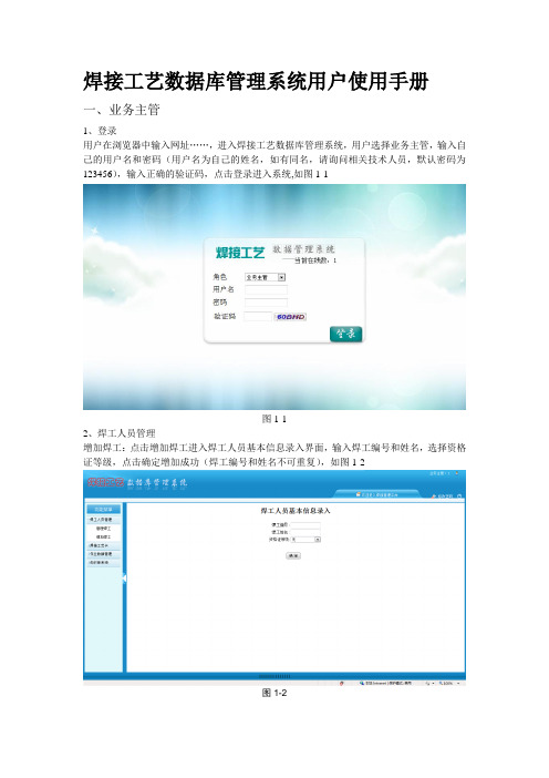
焊接工艺数据库管理系统用户使用手册一、业务主管1、登录用户在浏览器中输入网址……,进入焊接工艺数据库管理系统,用户选择业务主管,输入自己的用户名和密码(用户名为自己的姓名,如有同名,请询问相关技术人员,默认密码为123456),输入正确的验证码,点击登录进入系统,如图1-1图1-12、焊工人员管理增加焊工:点击增加焊工进入焊工人员基本信息录入界面,输入焊工编号和姓名,选择资格证等级,点击确定增加成功(焊工编号和姓名不可重复),如图1-2图1-2管理焊工:点击管理焊工进入焊工人员基本信息管理界面,这里可以对焊工信息进行查询、删除和修改。
如图1-3查询:在文本框中输入焊工的编号或姓名,点击查询获得查询结果。
(此处为模糊查询),单击显示全部,获得所有焊工信息。
删除:单击每一行数据最右边的删除按钮可对此行焊工数据进行删除,也可以通过多选按钮选择后点击删除按钮进行删除,删除时会弹出确认对话框,点击确认则删除,取消返回。
修改:单击修改按钮,进入焊工人员基本信息修改界面,编辑需要修改的内容,点击提交确认修改,点击返回则返回到焊工人员基本信息管理界面图1-33、焊接工艺卡查询工艺卡:点击查询工艺卡进入工艺卡查询界面,选择查询条件(产品名称、工艺卡号、焊接方法、编制人、编制日期等等),输入查询条件,并且选择查询条件之间的关系(并且、或者),进行查询。
(注:产品名称和工艺卡号为模糊查询,其余为精确查询)。
查询完成后可以点击查询结果中的工艺卡号,显示此工艺卡的详细信息。
如图1-4图1-4打印工艺卡:(接上)在焊接工艺卡下方,可以进行工艺卡的打印预览和页面设置,确认无误后点击打印进行打印工艺卡。
如图1-5图1-5审批工艺卡:点击审批工艺卡进入待审批工艺卡界面。
此界面会罗列出所有待审核的工艺卡,点击删除按钮可以删除信息不全的工艺卡,点击审批或卡号可以查看此工艺卡的详细信息,查看完信息后可以审批通过、不通过、或者直接删除。
- 1、下载文档前请自行甄别文档内容的完整性,平台不提供额外的编辑、内容补充、找答案等附加服务。
- 2、"仅部分预览"的文档,不可在线预览部分如存在完整性等问题,可反馈申请退款(可完整预览的文档不适用该条件!)。
- 3、如文档侵犯您的权益,请联系客服反馈,我们会尽快为您处理(人工客服工作时间:9:00-18:30)。
FRNC-5PC工艺计算软件操作指南目录1 总则 (3)1.1主要应用 (3)1.2相关标准及参考书籍 (3)2 软件简介 (4)2.1软件使用范围 (4)2.1软件计算方法 (5)2.1.1固定发热量(固定燃料量) (5)2.1.2固定热负荷 (5)3 输入部分 (6)3.1燃烧室输入 (6)3.1.1 Characteristic (6)3.1.2 Furnace type (7)3.1.3 Furnace dimension (7)3.1.4 Flue Gas “Take-Off” (8)3.1.5 The ID’s of Coil Sections in Firebox (9)3.2对流室输入 (10)3.2.1 Characteristic (10)3.2.2 Internal Duct Dimensions (10)3.2.3 Coil Section, Q-Bank, or Air Preheater ID (11)3.3烟囱输入 (11)3.3.1 Characteristic (11)3.3.2 Geometry (12)3.4管路输入 (12)3.4.1 Geometry (13)3.4. 2 Process fluid (13)3.4.3 Geometry I (14)3.4.4 Geometry II (14)3.4.5 Additional data (16)3.4.6 Additional data (17)3.5炉管数据输入 (18)3.5.1 General characteristics (18)3.5.2 Fin type and diameter (19)3.5.3 Fin data (20)3.6物料数据输入 (20)3.6.1 Process stream Characteristic (20)3.6.2Condition (21)3.7燃烧数据输入 (22)3.7.1 Firing data (22)3.7.2 Bridge wall temperature (23)3.7.3 Fuel #1 (24)3.8燃料数据输入 (25)3.8.1 Identification (25)3.8.2 Composition (26)3.9热损失输入 (26)3.10注入水蒸气/水数据 (27)3.11Q-B ANK输入 (28)3.12空气数据输入 (28)3.13空气预热器输入 (29)3.13.1 General Characteristic (30)3.13.2 Specification (30)3.14物理数据输入 (31)3.14.1 自动生成的物理性质 (31)3.14.2 直接输入的物理数据 (31)3.14.3 仅仅生成的物理属性数据 (32)4 输出部分 (32)4.1输入数据的重现 (32)4.2输入数据的处理 (32)4.3物理属性数据的重现 (32)4.4计算过程输出 (33)4.4最终结果输出 (33)1总则1.1 主要应用本手册规定了FRNC-5PC软件的使用方法和步骤等。
本手册适用于以气体、液体为燃料的管式加热炉、裂解炉、烃类转化炉等常用的工业炉的传热计算。
1.2 相关标准及参考书籍DIRECT FIRED HEATER SIMULATION SOFTWARE COMPUTER MANUAL PFR公司加热炉模拟软件操作指南HG/T 20541-2006 化学工业炉结构设计规定HG/T 20525-2006 化学工业管式炉传热计算设计规定SH/T 3036-2003 一般炼油装置用火焰加热炉SH/T 3045-2003 石油化工管式炉热效率设计计算SY/T 0538-2004 管式加热炉规范SY/T 0540-2006 石油工业用加热炉型式与基本参数钱家麟等.管式加热炉(第二版).中国石化出版社.2009.9李少萍、徐心茹。
石油加工过程设备.华东理工大学.2009.52软件简介FRNC-5PC软件是PFR公司的一款加热炉工艺计算软件,它的适用范围包括炼油厂除制氢转化炉外的所有加热炉,既可以用于新炉子的设计计算,迅速的进行多方案比较和优化设计;也可以模拟在役炉子的操作工况,对操作数据进行评价以改善工艺操作,预测物料组成、注汽(水)量和位置以及燃料类型等的改变对加热炉的影响,目前我国北京院、洛阳院等设计院的加热炉工艺计算都使用的是这个软件。
2.1软件使用范围FRNC-5PC软件能对炼油厂和石化厂大部分的加热炉进行性能模拟和效率预测,其中包括:常压炉减压炉重整炉焦化炉减粘炉煤炭液化炉余热回收和蒸汽发生炉重沸炉润滑油馏分油和蜡加热炉热解炉加热炉关键的过程和条件都可以在加热炉任何部位进入、输出,流程模拟、预测热量转换和压降等方法先进科学。
可以模拟加热炉的部分包括:综合工艺过程多个盘管布局多个燃烧室多个管路和翅片类型对流室部分转油线管道流体形态烟囱配件FRNC-5PC软件的计算范围包括:辐射及全炉热效率两相流流型火墙温度两相流沸腾形式各部位烟气温度两相流传热及压降辐射及对流热强度烟气侧传热及抽力管壁金属温度露点腐蚀温度翅片或顶头尖端温度烘炉预测该软件可以模拟多股物料的复杂工况,对工艺、设计和运营部门的工程师来说,它是一个科学、节省时间的高效软件。
2.1软件计算方法该软件可以按照两种方式进行模拟,一种是固定发热量(固定燃料量),另一种是固定热负荷。
2.1.1固定发热量(固定燃料量)即燃料速率由用户给定,软件计算出热负荷(吸热量)、每种物料的最终条件和中间结果以及其它性能参数,其计算步骤如下:2.1.2固定热负荷即物流吸热由用户给定,所需的供热量及燃料量由程序求出,同时计算出其它性能参数,其计算步骤如下:3输入部分FRNC-5PC软件的输入部分主要有下面几部分:机械数据:燃烧室,对流,管道,烟囱,管道,管路配置和炉管尺寸;过程数据:物料流量和终端工艺条件(温度,压力);物理性质:油气流的可自动生成的热力学和输运性质;燃烧信息:燃油流量,燃料成分,燃烧空气温度和过剩空气系数。
输入部分是按照加热炉的各个部分分为不同的逻辑块,每一部分的输入都会有一个关键词和描述,表2.1说明加热炉各个部分的关键词和相应的描述。
表2.1加热炉主要部分和需要的数据3.1 燃烧室输入燃烧室是加热炉热量输入部位,在FRNC-5PC软件中至少应输入一个燃烧室的数据,本软件最多可模拟五个不同的燃烧室,已成功建立燃烧室模型的类型有:圆筒炉、箱式炉和梯台炉。
3.1.1 Characteristic本部分包括三个输入部分。
1.Firebox ID燃烧是号和输入一到两位数字,这个数不不需要唯一,可与后面的管路系统、炉管数据、燃料的号一样。
2.Number of parallel “identical” firebox(默认为1)如果平行的燃烧室具有相同工艺流、燃烧状态,它们就称为“相同”,此时只需要输入一组数据就行.3.Parallel firebox ID number如果平行的燃烧室具有不同的工艺流、燃烧状态,它们就称为“不相同”,使用者在此输入一个数,同时软件将在输入部分出现它的号。
以上输入界面见下图。
3.1.2 Furnace type加热炉型式有圆筒炉、箱式炉、屋型炉和梯台炉。
其界面如下:3.1.3 Furnace dimension加热炉直径输入是用来计算燃烧室耐火数量,直径指的是从内防火墙之间的尺寸,各个炉型的尺寸表示如下图:如果加热炉中间有火墙,其数据应输入,输入界面如下:3.1.4 Flue Gas “Take-Off”1.烟气离开燃烧室的开口位置及尺寸输入是为了对燃烧室进行粗计算,默认的方式为“顶、中心”。
2.Inner Dimensions of Flue Gas Take-Off如果烟气离开燃烧室开口形状为长方形,则在此处输入长和宽,如果开口为圆型,则在第一个里面输入圆的直径,第二个不输入。
这个尺寸决定了燃烧室辐射到对流室光管的面积。
3.Screen Opening Code(默认为“不”)不打对号表示开口没有遮挡,打对号表示开口被辐射管和光管遮挡,如果出口被耐火材料遮蔽使热量辐射回燃烧室,这种情况也应打对号,对于对流室有光管的情况也要打对号,这部分的输入界面如下:3.1.5 The ID’s of Coil Sections in Firebox至少一组管路数据或者“Q-Bank”数据应该输入,最多可以输入9组数据。
管路系统是具有相同工艺流和机械数据的炉管组成Q-Bank它是一组从烟气中增加或移出热量的管路系统,它没有具体的机械数据,编号从90~99,Q-Bank在对对流室进行热交换研究时起作用。
其输入界面如下:3.2 对流室输入在对流室里,炉管相对于烟气串联或平行,烟气可能向上、向下或水平穿过这些炉管,光管部分的辐射热量度部分来自燃烧室,对流室的其它部分的辐射热量则来自耐火墙和烟气的直接辐射得来。
如果在对流室热量损失的比例较大,那么在后面的Heat Loss章节就应该输入数据。
3.2.1 Characteristic本部分包含三个输入,ID输入方法与前面的燃烧室相同,第二部分输入的是烟气进入和离开的加热炉部分的ID号,第三部分为流动阻力阻尼,默认为0.3.2.2 Internal Duct Dimensions如果对流室为长方形,那么输入它的长宽高,如果为圆柱形,那么在第一个里输入它的直径,第二个不填,在第三个里输入高度。
选择上、下还是水平根据的是摩擦气流的方向,它的作用是粗略计算,摩擦、动量和重力在烟气穿过加热炉的过程中一直存在,因此气流方向对于粗略计算就有很大意义。
其输入界面如下:3.2.3 Coil Section, Q-Bank, or Air Preheater ID软件支持10组数据的输入,其输入方法与燃烧室相同。
3.3 烟囱输入烟囱是加热炉中垂直圆筒形的部分,如果烟囱数据没有输入,软件将不会对输入的加热炉数据进行模拟,但烟气压降会在加热炉的各个部分显现。
烟囱的热损失在粗略计算时有很大作用。
3.3.1 Characteristic本部分包含两个输入,ID输入方法与前面的相同,一个加热炉最多允许有两个平行的烟囱;第二部分输入的是烟气进入烟囱的ID号。
3.3.2 Geometry为了避免不同的外径D I和内径D E,软件输入的是几何直径D G,其公式如下:D=G输入的时候注意:烟囱直径的单位为mm,高度单位为m。
流体阻力阻尼(默认为1.5倍速度头)3.4管路输入软件支持最少1组最多89组的管路数据输入,管路是一个或多个炉管的组成,他们具有以下特征:1.具有相同的方向和直径;2.具有相同的工艺流;3.进入管路的物料来自于同一个入口,并且物料具有相同的温度和压力;4.位于加热炉的位置相同;5.在燃烧室炉管相对于火焰的朝向相同;6.过程流体一直保持和入口一样的管程数。