
wincc实现软冗余手册
1 Software RedundancyWithin WinCC, the software redundancy feature makes it possible to monitorcritical sections of a plant by using a redundant connection to several PLCs.Software redundancy considerably improves reliability when critical plantsections are to be monitored. For example, a redundant connection to twoPLCs means that one PLC takes over if the other PLC fails. Using softwareredundancy does not mean that you can only establish redundant connectionsto the PLCs configured. It is still possible to connect any PLC in a non-redundant layout. The switchover between redundant PLCs is performedautomatically in the event of a malfunction. However, a manual switchover isalso possible by specifying a tag (@ForceConnectionState).NoteEstablishing a redundant connection requires two PLCs.Setting up software redundancy:In order to use software redundancy under WinCC, the following settings are required in the Control Center:Step 1The computer properties must be set to the following values:Step 2Within the Alarm Logging system, the "short-term archive" must beactivated:If the "short-term archive" has not yet been activated, proceed as follows: In the navigation window, open the pop-up menu of the "Archives" object and select the "Add/Remove" menu item. Within the "Assign StorageParameters" dialog box, activate the "Short-Term Archive Active" check box.Step 3Within the Alarm Logging, the system messages must be retrieved; select the "Options" and "WinCC System Messages" menu items for thispurpose. In the "WinCC system messages" dialog box, activate the "Create New System Messages Only" option and press the "Create" button. This procedure retrieves the system messages associated with softwareredundancy.Step 4By means of the "DynWizEdit.exe" program, integrate the DynamicWizard for software redundancy into the WinCC system (GraphicsDesigner). This integration procedure requires the following steps: In the Windows Explorer, start the "C:\Siemens\WinCC\bin\DynWizEdit.exe"program. Select the "German" language in the toolbar. Retrieve the"C:\Siemens\WinCC\wscripts\wscripts.deu\SW_Redundanz.wnf" script by selecting the "Dynamic Wizard" and "Retrieve Wizard Script" menuitems. The compilation progress is shown in the output window. After the compilation has been completed successfully, the new entry "EstablishRedundant Connection" appears in the "Dynamic Wizard" window.Step 5Integrate the "SIMATIC S7 PROTOCOL SUITE" communications driver within the tag management.Step 6Within the required bus type (e.g. MPI), create a logical connection in the "SIMATIC S7 PROTOCOL SUITE" communications driver. Give anexpressive name to this connection.Step 7Open an existing picture in the Graphics Designer. Within the Dynamic-Wizard (in the "System Functions" tab), start the "Establish RedundantConnection" program by double-clicking.Step 8Press the "More" button in the welcome screen.Step 9Select the main connection in the "Set Options" dialog box. Then press the "More" button.Step 10Edit the settings for the back-up connection in the "Set Options" dialog box. Then press the "More" button. The "Automatic Switchover" check box must be active (default setting).The settings for the back-up connection (S7 network address) can be found in the "Connection" tab. Access this tab via the connection propertiesdialog box for the connection.Step 11The settings you specified are displayed in the final "Finished" dialog box.By pressing the "Finish" button, connection-specific internal tags arecreated in a tag group. This tag group is stored within the tag management under "SIMATIC S7 PROTOCOL SUITE" and the associated channelunit.NoteBy pressing the "Back"u button, you can go back one step and make any necessary changes.1.1 Connection-specific Internal TagsConnection control is accomplished by means of connection-specific internaltags. The connection-specific internal tags are created by a wizard. The nameof a connection-specific internal tag is composed of the name of the associatedconnection and an identifier. The connection name is provided with a '@'prefix to identify it as a system tag. Example: "@connectionname@identifier". All connection-specific internal tags are assembled to forma "@connection name" tag group.NoteOnly if the associated connection is ready for operation does the WinCC datamanager permit access to connection-specific tags. However, it is possible tohave read and write access to connection-specific internal tags independentlyof the connection status.The following system tags are available for SIMATIC S7 PROTOCOL SUITEsoftware redundancy:@ConnectionStateMeaning:connection statusType:DWORDAccess:readDefault:0 = "faulty"The current connection status can be determined by means of the'ConnectionState' tag.0 = connection faulty1 = connection ready for operation@ConnectionErrorMeaning:error causeType:DWORDAccess:readDefault:0 = "no error"The tag contains an error cause describing the reason why theconnection was interrupted. Default = 0, i.e. connection not yetestablished or without error. When establishing a connection, the tag isloaded with 0 (no error) again. The error code is interpreted in achannel-specific manner. The S7 channel stores the S7 DOS error codehere.0 = no error<> 0 = S7 DOS error code@ConnectionErrorStringMeaning:error cause as stringType:TEXT8 [128]Access:readDefault:"" = "no error"The tag contains the error cause in the format of a string describing the reason why the connection was interrupted. The string is put out in the language currently selected. Default = "", i.e. connection not yetestablished or without error. The following texts are entered in the S7channel in English, without regard to the selected language."No Error"= No error"Error hhhh"= hhhh error occurred(hhhh = S7 DOS hexadecimal error code)@ConnectionErrorCountMeaning:communication error counterType:DWORDAccess:readDefault:0 = "no error"The value of this tag is incremented by 1 each time a connection isinterrupted.In the event of an overflow the count starts again with 0.@ConnectionEstablishModeMeaning:connect modeType:DWORDAccess:writeDefault: 1 = "automatic"This tag enables you to specify a connection to be establishedautomatically. The S7 channel then attempts to reestablish a failedconnection at intervals of approx. 4 seconds. If a value = 0 is enteredin this tag, the connection will not be reestablished automatically atintervals of 4 seconds, but remains interrupted.Writing the @ConnectionEstablishMode tag takes the following effect:0 = manual connecting mode-> deactivate automatic connecting<> 0 = automatic connect mode-> activate automatic connecting@ForceConnectionStateMeaning:preferred connection statusType:DOWRDAccess:writeDefault: 1 = "established"This tag can be used to notify the channel of the preferred connection status. Usually this tag has the value 1, i.e. the channel attempts toestablish the connection (at regular intervals of approx. 4 seconds, ifapplicable). If the value 0 is written to this tag, the channel interrupts the connection.Writing to this tag takes the following effect:0 = preferred connection status: connection interrupted-> if connection established-> cause connection to be interrupted1 = preferred connection status: connection established-> if connection interrupted-> cause connection to be established@ForceConnectionAdressMeaning:selecting the connection addressType:DWORDAccess:writeDefault:0 = "configured"This tag specifies which of the connection addresses is to be used for establishing the connection.Writing to this tag takes the following effect:0 = connection via configured connection parameters-> if @ForceConnectionAddress previously 1-> cause connection to be interrupted1 = connection via alternative connection parameters-> if @ForceConnectionAddress previously 0-> cause connection to be interrupted->If connect mode is set to "automatic", the connection isautomatically established with the corresponding address.@AlternateConnectionAdressMeaning:Alternative connection addressType:TEXT8 [255]Access:writeDefault:"..." = "configured"The alternative connection address string can be entered in this tag.This is the same string as the one which is displayed as connectionparameter in the WinCC Control Center. The string is channel-specific. On system start-up (runtime), the configured address isentered here as default for the S7 channel. If an address has not beenconfigured yet, the text "Illegal Address" is entered for the S7 channel.Example of an address specified for an S7 PLC with station address 3via MPI: “MPI,3 0,,0,0,02“Writing to this tag takes the following effect:->If the address is changed by the write process, the "Connection via alternative connection parameters" setting causes the connection to be interrupted.->If the "automatic" connect mode has been set, the connection isestablished automatically, using the address just previously written.1-112 Master-Reserve Change-over on the S7When the Dynamics Wizard has finished setting up the redundant-backup link, you canextend the script by adding the …Master-Reserve Change-over“ option.To do so, you open the script under …Global Script -> Actions -> Global Actions“. If yourselected connection is called …CPU_3“ as in the illustrations above, open @CPU_3.pas.Control Center- (Projekt.MCP)ProjektVariablenhaushaltEditorenGlobal ScriptAktionenGlobale Aktionen CPU_3.pas CPU_4.pas CPU_5.pasHaving opened it, you then insert the sequence printed in bold type and highlighted ingray. Here too it is assumed that your connection is called …CPU_3“. If you have used adifferent name, replace each occurrence of …CPU_3“ with the name you have used. The bitvariable …SWR.Standby“ is the bit …Reserve“ from the status word (DW 9.1) from theinstance DB of the call for FB101 …SWR_ZYK“. If you have used a different name forthis, replace the name accordingly............{MSRTStopMsgService ( ServiceID, &Error );}If ( GetTagDWordWait( "@CPU_3@ConnectionState" ) == 0 ){SetTagDWord( "@CPU_3@ForceConnectionState", 1 );}else{if ( GetTagBitWait( "SWR.Standby" ) == TRUE ){SetTagDWord( "@CPU_3@ForceConnectionState", 0 );}}return 1;}}2-12Note: you can add the …Standby bit“ to the structure for the redundant software backup screen block (see section 7.2.2 in the user documentation for the redundant-backup software blocks) as follows:Name Data type Offset BitWORD Status WORD00BIT MasterSwitch BIT20BIT RedTurnOn BIT29BIT RedTurnOff BIT28BIT Standby BIT092-13。
wincc冗余系统与客户机的配置

冗余系统配置冗余系统配置步骤如下:1、用移动存储设备将一个组态好的项目复制服务器;2、打开刚复制过来的项目,找到里面的*.mcp文件,并双击将之打开;3、双击“冗余”;4、在打开的画面中填写、勾选相关的内容之后,单击“确定”;5、左击“服务器数据”;6、将右面编辑窗口中的前项目删除;7、右击“服务器数据”,在弹出的菜单里选择“创建”,并单击“确定”关闭对话框;8、右击“服务器数据”,在弹出的对话框中选择“隐含更新”选项,并将里面的复选框都勾选,单击“确定”关闭对话框;9、双击项目浏览窗口的“用户管理器”;10、右击“Administrator-Group”,在弹出得菜单项中选择“添加用户”;11、输入“用户名****”与“密码****”,单击“确定”关闭对话框;12、选中“远程激活”与“远程组态”;13、右击项目浏览器中的“计算机”,出现“添加新计算机”选项;14、添加计算机名“PC01”、“PC02”、“PC03”“PC04”、“PC05”、“PC08”、“PC10”15、右击“S1”,在弹出的菜单里选择“属性”;16、选择“图形运行系统”,在出现的“属性”栏中勾选“全屏”,在“起始画面”项点击“浏览”,选择“登陆界面.PDL”,单击“确定”关闭对话框;17、打开项目复制器Project Duplicator;18、将项目复制到伙伴服务器的共享文件夹的Project目录下;19、单击工具栏上的“激活运行”按钮,运行项目;20、打开备份服务器的项目,按照配置服务器的步骤配置备份服务器,配置完成以后运行项目就可以了;21、接下来就需要配置客户机了,每台客户机都需要进行配置。
注:一定要在主服务器完全运行起来以后再配置备份服务器上的项目客户机的配置客户机的配置步骤:1、退出原来的项目;2、运行WinCC Explorer应用程序;3、新建“客户端项目”→输入“项目名称”(命名方式为PC01-1101) →创建;4、单击工具栏上的“打开”按钮→在弹出的对话框中选择“网络邻居”→找到“Project”文件夹→双击要运行的项目文件夹→双击应用程序;剩下步骤与服务器配置类似,不再赘述。
构建一个WinCC冗余项目

如果需要使用WinCC冗余系统时,请仔细阅读下面的文档,它将解决以下几个问题:(1)WinCC冗余有什么样的功能?(2)需要购买什么样的授权?(3)应该安装在怎么样的系统上?(4)如何为用户配置操作系统的权限?(5)如何创建WinCC的冗余服务器项目?(6)如何创建WinCC的客户机?(7)如何诊断冗余错误和识别冗余工作状态?除此之外,对于需要引申的内容,该文档还提供了相关内容的链接地址和帮助路径,方便用户更加系统地学习WinCC冗余内容。
1.冗余系统简介WinCC冗余是两台互联的WinCC并行工作,并基于事件进行同步,提高了系统的可靠性。
WinCC冗余具有下列功能:(1)故障自动识别,故障恢复后自动同步变量记录、报警消息、用户归档。
(2)在线同步变量记录、报警消息、用户归档。
(3)服务器故障时,客户端自动切换到可用的服务器。
(4)自动识别伙伴服务器的状态,并实时显现主备服务器的工作状态。
(5)自动生成系统故障信息,及时发现服务器软件故障。
如果项目中有上述需求,WinCC冗余可以方便项目的实施。
2.搭建WinCC冗余项目的必要条件2.1 软件和授权表012.2 安装系统环境建议使用Windows Server 2003或者Windows Server 2003 R2对于单用户的冗余系统,也可使用Windows XP操作系统。
更详细的兼容性列表,可以参考:87957163.组态WinCC冗余系统3.1 创建Windows用户在两台服务器上,创建相同的用户名和密码。
步骤:计算机管理里面打开本地用户和组◊管理工具◊(1)在Windows开始图01(2)创建一个新用户或者使用默认的Administrator(3)对于新建用户,在隶属于中,为用户分配Administrator,SIMATIC HMI和SQLServer2005MSSQLUSER$本地计算机名称$WinCC三个用户组。
对于默认Administrator用户,检查是否属于上述三个组。
wincc实现软冗余手册

wincc实现软冗余手册wincc实现软冗余手册wincc实现软冗余手册wincc实现软冗余手册wincc实现软冗余手册wincc实现软冗余手册wincc实现软冗余手册wincc 实现软冗余手册wincc实现软冗余手册wincc实现软冗余手册wincc实现软冗余手册wincc实现软冗余手册wincc实现软冗余手册1 Software RedundancyWithin WinCC, the software redundancy feature makes it possible to monitorcritical sections of a plant by using a redundant connection to several PLCs.Software redundancy considerably improves reliability when critical plantsections are to be monitored. For example, a redundant connection to twoPLCs means that one PLC takes over if the other PLC fails. Using softwareredundancy does not mean that you can only establish redundant connectionsto the PLCs configured. It is still possible to connect any PLC in a non- redundant layout. The switchover between redundant PLCs isperformedautomatically in the event of a malfunction. However, a manual switchover isalso possible by specifying a tag (@ForceConnectionState).NoteEstablishing a redundant connection requires two PLCs.1-1wincc实现软冗余手册wincc实现软冗余手册wincc实现软冗余手册wincc实现软冗余手册wincc实现软冗余手册wincc实现软冗余手册wincc 实现软冗余手册wincc实现软冗余手册wincc实现软冗余手册wincc实现软冗余手册wincc实现软冗余手册wincc实现软冗余手册1-2Setting up software redundancy:In order to use software redundancy under WinCC, the following settings arerequired in the Control Center:Step 1The computer properties must be set to the following values:Step2Within the Alarm Logging system, the “sh ort-term archive" must be activated:If the "short-term archive" has not yet been activated, proceed as follows:In the navigation window, open the pop-up menu of the "Archives" objectand select the "Add/Remove" menu item. Within the "Assign StorageParameters" dialog box, activate the "Short-Term Archive Active" checkbox.wincc实现软冗余手册wincc实现软冗余手册wincc实现软冗余手册wincc实现软冗余手册wincc实现软冗余手册wincc实现软冗余手册wincc 实现软冗余手册wincc实现软冗余手册wincc实现软冗余手册wincc实现软冗余手册wincc实现软冗余手册wincc实现软冗余手册Step 3Within the Alarm Logging, the system messages must be retrieved; selectthe "Options" and "WinCC System Messages" menu items for thispurpose. In the "WinCC system messages" dialog box, activate the "CreateNew System Messages Only" option and press the "Create" button. Thisprocedure retrieves the system messages associated with softwareredundancy.1-3wincc实现软冗余手册wincc实现软冗余手册wincc实现软冗余手册wincc实现软冗余手册wincc实现软冗余手册wincc实现软冗余手册wincc 实现软冗余手册wincc实现软冗余手册wincc实现软冗余手册wincc实现软冗余手册wincc实现软冗余手册wincc实现软冗余手册1-4Step 4By means of the "DynWizEdit.exe" program, integrate the DynamicWizard for software redundancy into the WinCC system (GraphicsDesigner). This integration procedure requires the following steps: In theWindows Explorer, start the"C:\Siemens\WinCC\bin\DynWizEdit.exe"program. Select the "German" language in the toolbar. Retrievethe"C:\Siemens\WinCC\wscripts\wscripts.deu\SW_Redundanz.wnf" script byselecting the "Dynamic Wizard" and "Retrieve Wizard Script" menuitems. The compilation progress is shown in the output window. After thecompilation has been completed successfully, the new entry "Establish Redundant Connection" appears in the "Dynamic Wizard"window.Step 5Integrate the "__ S7 __L SUITE" communications driverwithin the tag management.Step 6Within the required bus type (e.g. MPI), create a logical connection in the"__ S7 __L SUITE" communications driver. Give anexpressive name to this connection.Step 7Open an existing picture in the Graphics Designer. Within the Dynamic-Wizard (in the "System Functions" tab), start the "Establish RedundantConnection" program by double-clicking.wincc实现软冗余手册wincc实现软冗余手册wincc实现软冗余手册wincc实现软冗余手册wincc实现软冗余手册wincc实现软冗余手册wincc 实现软冗余手册wincc实现软冗余手册wincc实现软冗余手册wincc实现软冗余手册wincc实现软冗余手册wincc实现软冗余手册Step 8Press the "More" button in the welcome screen.Step 9Select the main connection in the "Set Options" dialog box. Thenpress the"More" button.1-5wincc实现软冗余手册wincc实现软冗余手册wincc实现软冗余手册wincc实现软冗余手册wincc实现软冗余手册wincc实现软冗余手册wincc 实现软冗余手册wincc实现软冗余手册wincc实现软冗余手册wincc实现软冗余手册wincc实现软冗余手册wincc实现软冗余手册Step 101-6Edit the settings for the back-up connection in the "Set Options" dialogbox. Then press the "More" button. The "Automatic Switchover" checkbox must be active (default setting).The settings for the back-up connection (S7 network address) can be foundin the "Connection" tab. Access this tab via the connection propertiesdialog box for the connection.wincc实现软冗余手册wincc实现软冗余手册wincc实现软冗余手册wincc实现软冗余手册wincc实现软冗余手册wincc实现软冗余手册wincc 实现软冗余手册wincc实现软冗余手册wincc实现软冗余手册wincc实现软冗余手册wincc实现软冗余手册wincc实现软冗余手册Step 11The settings you specified are displayed in the final "Finished" dialog box.By pressing the "Finish" button, connection-specific internal tags are created in a tag group. This tag group is stored within the tag managementunder "__ S7 __L SUITE" and the associated channelunit.NoteBy pressing the "Back"u button, you can go back one step and make anynecessary changes.1-7wincc实现软冗余手册wincc实现软冗余手册wincc实现软冗余手册wincc实现软冗余手册wincc实现软冗余手册wincc实现软冗余手册wincc 实现软冗余手册wincc实现软冗余手册wincc实现软冗余手册wincc实现软冗余手册wincc实现软冗余手册wincc实现软冗余手册1.1 Connection-specific Internal Tags1-8Connection control is accomplished by means of connection-specific internaltags. The connection-specific internal tags are created by a wizard. The nameof a connection-specific internal tag is composed of the name of the associatedconnection and an identifier. The connection name is provided with a '@'prefix to identify it as a system tag. Example:"@connectionname@identifier". All connection-specific internal tags are assembled to forma "@connection name" tag group.NoteOnly if the associated connection is ready for operation does the WinCC datamanager permit access to connection-specific tags. However, it ispossible tohave read and write access to connection-specific internal tags independentlyof the connection status.The following system tags are available for __ S7 __L SUITEsoftwareredundancy:@ConnectionStateMeaning:connectionstatusType:DWORDAccess:readDefault:0 = "faulty"The current connection status can be determined by means of the'ConnectionState' tag.0 = connection faulty1 = connection ready foroperation@ConnectionErrorMeaning:errorcauseType:DWORDAccess:readDefault:0 = "no error"The tag contains an error cause describing the reason why theconnection was interrupted. Default = 0, i.e. connection not yetloaded with 0 (no error) again. The error code is interpreted in ahere.0 = no error 0 = S7 DOS error code wincc实现软冗余手册wincc实现软冗余手册wincc实现软冗余手册wincc实现软冗余手册wincc实现软冗余手册wincc实现软冗余手册wincc 实现软冗余手册wincc实现软冗余手册wincc实现软冗余手册wincc实现软冗余手册wincc实现软冗余手册wincc实现软冗余手册@ConnectionErrorStringMeaning:Type:Access:Default:error cause as stringTEXT8 read"" = "no error"language currently selected. Default = "", i.e. connection not yetestablished or without error. The following texts are entered in the S7 channel in English, without regard to the selected language."No Error""Error hhhh"@ConnectionErrorCountMeaning:Type:Access:Default:= No error= hhhh error occurred(hhhh = S7 DOS hexadecimal error code)communication error counterDWORDread0 = "no error"The value of this tag is incremented by 1 each time a connection isinterrupted.In the event of an overflow the count starts again with0.@ConnectionEstablishModeMeaning:connect modeType:DWORDAccess:writeDefault:1 = "automatic"This tag enables you to specify a connection to be establishedautomatically. The S7 channel then attempts to reestablish a failedconnection at intervals of approx. 4 seconds. If a value = 0 is entered in this tag, the connection will not be reestablished automatically atintervals of 4 seconds, but remains interrupted.0 = manual connecting mode- deactivate automatic connecting0 = automatic connect mode- activate automatic connecting1-9wincc实现软冗余手册wincc实现软冗余手册wincc实现软冗余手册wincc实现软冗余手册wincc实现软冗余手册wincc实现软冗余手册wincc 实现软冗余手册wincc实现软冗余手册wincc实现软冗余手册wincc实现软冗余手册wincc实现软冗余手册wincc实现软冗余手册1-10@ForceConnectionStateMeaning:preferred connection statusType:DOWRDAccess:writeDefault:1 = "established"This tag can be used to notify the channel of the preferred connectionstatus. Usually this tag has the value 1, i.e. the channel attempts toestablish the connection (at regular intervals of approx. 4 seconds, ifapplicable). If the value 0 is written to this tag, the channel interruptsthe connection.Writing to this tag takes the following effect:0 = preferred connection status: connection interrupted- if connection established- cause connection to be interrupted1 = preferred connection status: connection established- if connection interrupted- cause connection to beestablished@ForceConnectionAdressMeaning:selecting the connection addressType:DWORDAccess:writeDefault:0 = "configured"This tag specifieswhich of the connection addresses is to be used forestablishing the connection.Writing to this tag takes the following effect:0 = connection via configured connection parameters- if @ForceConnectionAddress previously 1- cause connection to be interrupted1 = connection via alternative connection parameters- if @ForceConnectionAddress previously 0- cause connection to be interrupted-If connect mode is set to "automatic", the connection isautomatically established with the corresponding address.wincc实现软冗余手册wincc实现软冗余手册wincc实现软冗余手册wincc实现软冗余手册wincc实现软冗余手册wincc实现软冗余手册wincc 实现软冗余手册wincc实现软冗余手册wincc实现软冗余手册wincc实现软冗余手册wincc实现软冗余手册wincc实现软冗余手册@AlternateConnectionAdressMeaning:Alternative connection addressType:TEXT8Access:writeDefault:"..." = "configured"The alternative connection address string can be entered in this tag.This is the same string as the one which is displayed as connectionparameter in the WinCC Control Center. The string is channel-specific. On system start-up (runtime), the configured address isentered here as default for the S7 channel. If an address has not beenExample of an address specified for an S7 PLC with station address 3 via MPI: “MPI,3 0,,0,0,02“Writing to this tag takes the following effect:-If the address is changed by the write process, the "Connection via alternative connection parameters" setting causes the connection to beinterrupted.-If the "automatic" connect mode has been set, the connection isestablished automatically, using the address just previously written.1-11wincc实现软冗余手册wincc实现软冗余手册wincc实现软冗余手册wincc实现软冗余手册wincc实现软冗余手册wincc实现软冗余手册wincc 实现软冗余手册wincc实现软冗余手册wincc实现软冗余手册wincc实现软冗余手册wincc实现软冗余手册wincc实现软冗余手册2 Master-Reserve Change-over on the S7When the Dynamics Wizard has finished setting up the redundant-backup link, you canextend the script by adding the Master-Reserve Change-over“ option.To do so, you open the script under Global Script - Actions - Global Actions“. If yourselected connection is called CPU_3“ as in the illustrations above, open @CPU_3.pas.Control Center- (Projekt.MCP)ProjektVariablenhaushaltEditorenGlobal ScriptAktionenGlobale AktionenCPU_3.pasCPU_4.pasCPU_5.pasHaving opened it, you then insert the sequence printed in bold type and highlighted ingray. Here too it is assumed that your connection is call ed CPU_3“. If you have used adifferent name, replace each occurrence of CPU_3“ with the name you have used. The bitvariable SWR.Standby“ is the bit Reserve“ from the status word (DW 9.1) from theinstance DB of the call for FB101 SWR_ZYK“. If you have used a different name forthis, replace the name accordingly............{MSRTStopMsgService ( ServiceID, Error );}If ( GetTagDWordWait( "@CPU_3@ConnectionState" ) == 0 ){SetTagDWord( "@CPU_3@ForceConnectionState", 1 );}else{if ( GetTagBitWait( "SWR.Standby" ) == TRUE ){SetTagDWord( "@CPU_3@ForceConnectionState", 0 );}}return 1;}}2-12wincc实现软冗余手册wincc实现软冗余手册wincc实现软冗余手册wincc实现软冗余手册wincc实现软冗余手册wincc实现软冗余手册wincc 实现软冗余手册wincc实现软冗余手册wincc实现软冗余手册wincc实现软冗余手册wincc实现软冗余手册wincc实现软冗余手册Note: you can add the Standby bit“ to the structure for the redundant software backupscreen block (see section 7.2.2 in the user documentation for the redundant-backupsoftware blocks) as follows:NameData typeOffsetBit。
构建一个WinCC冗余项目

如何构建一个WinCC冗余项目如果需要使用WinCC冗余系统时,请仔细阅读下面的文档,它将解决以下几个问题:(1)WinCC冗余有什么样的功能?(2)需要购买什么样的授权?(3)应该安装在怎么样的系统上?(4)如何为用户配置操作系统的权限?(5)如何创建WinCC的冗余服务器项目?(6)如何创建WinCC的客户机?(7)如何诊断冗余错误和识别冗余工作状态?除此之外,对于需要引申的内容,该文档还提供了相关内容的链接地址和帮助路径,方便用户更加系统地学习WinCC冗余内容。
1.冗余系统简介WinCC冗余是两台互联的WinCC并行工作,并基于事件进行同步,提高了系统的可靠性。
WinCC冗余具有下列功能:(1)故障自动识别,故障恢复后自动同步变量记录、报警消息、用户归档。
(2)在线同步变量记录、报警消息、用户归档。
(3)服务器故障时,客户端自动切换到可用的服务器。
(4)自动识别伙伴服务器的状态,并实时显现主备服务器的工作状态。
(5)自动生成系统故障信息,及时发现服务器软件故障。
如果项目中有上述需求,WinCC冗余可以方便项目的实施。
2.搭建WinCC冗余项目的必要条件2.1 软件和授权表 012.2 安装系统环境建议使用Windows Server 2003或者Windows Server 2003 R2对于单用户的冗余系统,也可使用Windows XP操作系统。
更详细的兼容性列表,可以参考:87957163.组态WinCC冗余系统3.1 创建Windows用户在两台服务器上,创建相同的用户名和密码。
步骤:计算机管理里面打开本地用户和组管理工具(1)在Windows开始图 01(2)创建一个新用户或者使用默认的Administrator(3)对于新建用户,在隶属于中,为用户分配Administrator,SIMATIC HMI和 SQLServer2005MSSQLUSER$本地计算机名称$WinCC三个用户组。
S7-300软冗余调试总结--WINCC组态(最新整理)
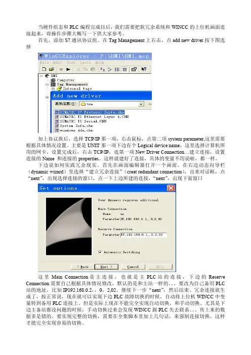
这 里 Main Connection 是 主 连 接 , 也 就 是 主 PLC 站 的 连 接 , 下 边 的 Reserve Connection 需要自己根据具体情况修改,默认的是和主站一样的。。。要改为自己备用 PLC 站的地址,比如 IP192.168.0.2,,0,2,02。继续下一步“next”,然后结束。冗余连接就生 成了,按正常说,现在就可以实现下边 PLC 故障切换的时候,自动将上位机 WINCC 中变 量转到备用 PLC 连接上。但是实际上现在不能完全实现自动切换,和手动切换。尤其是下 边主备站都没问题的时候,手动切换过来会发现 WINCC 跟 PLC 失去联系。。。传上来的数 据多是错的。要实现完整的切换,需要在全集脚本里加上几句话,来强制连接切换,这样 才能完全实现容易的切换。
当我们上边冗余连接建立以后,在变量组里会自动生成一个@sw 变量组(其中 SW 是 前边建立的连接的名称),这个变量组里的变量在后边要用到。打开全局脚本编辑器 Global Scrip C 在左边项目浏览栏里边找:ActionsActions:XXX,其中 XXX 为你的计算机名。 在这个SW 就是刚刚在 TCP/IP 协议项下建立的那 个连接的名字。打开这个文件,将编辑窗口拉到最下边,将紫色部分代码复制添加到上下 文相对应的位置。
参考文献:S7300S7400SIMITIC S7 的软冗余 wincc 实现软冗余手册(英文)
{ SetTagDWord( "@sw@ForceConnectionState", 0 ); } } return 1; 这其中的几个变量"@sw@ConnectionState", "@sw@ForceConnectionState"这两个变量 在前边说到的@SW 变量组里边有。其中的 SW 是连接的名字,需要对应上自己前边建的连 接的名字。"SWR_wincc.Standby"这个变量就是 FB101 冗余程序块的背景数据块中的变量 DB***.DBX9.1, ***是在 PLC 冗余程序中调用冗余程序时自己设定的背景数据块号,我用 的是 DB101,所以我这里变量就连接 DB101.DBX9.1 这个数据位。 好啦,这样就可以实现手动自动切换啦。。。当然手动切换可以自己按照 DB101 的定义去手 动生成变量做,也可在网上搜索《S7300S7400SIMITIC S7 的软冗余》这个文档,里边有 介绍一个系统自带的手动切换冗余的模板,很方便。。。
西门子 WinCC S7-400H 冗余连接 操作指南

/CN/view/zh/108987749C o p y r i g h t S i e m e n s A G C o p y r i g h t y e a r A l l r i g h t s r e s e r v e d问题描述:从V8.2开始,SIMATIC NET 支持SOFTNET-IE S7 REDCONNECT VM ,即普通网卡都可以在虚拟机环境中使用并建立WinCC 和S7-400H 的容错连接。
注意:从SIMATIC NET V8.2开始,也可以在实际的计算机环境中使用普通网卡直接建立WinCC 和S7-400H 的容错连接C o p y r i g h t S i e m e n s A G C o p y r i g h t y e a r A l l r i g h t s r e s e r v e d回答:硬件和软件环境可以通过VMware 官方网站查询支持ESXi 硬件直通的服务器列表,本例中使用的HP Compaq 8200 Elite 。
服务器硬件配置如表1所示:指标 HP Compaq 8200 Elite CPU Intel Core i5 2400 3.1GHz (4Core)内存 26GB DDR3 1600MHz 硬盘 500G普通网卡Intel 82579LM Gigabit表1服务器、管理机和客户机的软件配置如表2所示:计算机 软件配置服务器VMware ESXi Server 5.5 Updata1 管理机 (工程师站)Windows 7 Ultimate SP1 VMware vSphere Client 5.5 STEP 7 Professional 2010 SR3WinCC V7.2 Update3 SIMATIC Net V12表2服务器上运行的虚拟机的软件配置如表3所示:软件操作系统 Windows Server 2008 R2 Standard SP1 SIMATICWinCC V7.2 Update3 SIMATIC Net V12表3操作步骤ESXi 服务器和管理机的安装和配置,请参考相关文档,在这里不再赘述。
构建一个WinCC冗余项目
如果需要使用WinCC冗余系统时,请仔细阅读下面的文档,它将解决以下几个问题:(1)WinCC冗余有什么样的功能?(2)需要购买什么样的授权?(3)应该安装在怎么样的系统上?(4)如何为用户配置操作系统的权限?(5)如何创建WinCC的冗余服务器项目?(6)如何创建WinCC的客户机?(7)如何诊断冗余错误和识别冗余工作状态?除此之外,对于需要引申的内容,该文档还提供了相关内容的链接地址和帮助路径,方便用户更加系统地学习WinCC冗余内容。
1.冗余系统简介WinCC冗余是两台互联的WinCC并行工作,并基于事件进行同步,提高了系统的可靠性。
WinCC冗余具有下列功能:(1)故障自动识别,故障恢复后自动同步变量记录、报警消息、用户归档。
(2)在线同步变量记录、报警消息、用户归档。
(3)服务器故障时,客户端自动切换到可用的服务器。
(4)自动识别伙伴服务器的状态,并实时显现主备服务器的工作状态。
(5)自动生成系统故障信息,及时发现服务器软件故障。
如果项目中有上述需求,WinCC冗余可以方便项目的实施。
2.搭建WinCC冗余项目的必要条件2.1 软件和授权表012.2 安装系统环境建议使用Windows Server 2003或者Windows Server 2003 R2对于单用户的冗余系统,也可使用Windows XP操作系统。
更详细的兼容性列表,可以参考:87957163.组态WinCC冗余系统3.1 创建Windows用户在两台服务器上,创建相同的用户名和密码。
步骤:计算机管理里面打开本地用户和组◊管理工具◊(1)在Windows开始图01(2)创建一个新用户或者使用默认的Administrator(3)对于新建用户,在隶属于中,为用户分配Administrator,SIMATIC HMI和SQLServer2005MSSQLUSER$本地计算机名称$WinCC三个用户组。
对于默认Administrator用户,检查是否属于上述三个组。
wincc冗余问题
如果需要使用WinCC冗余系统时,请仔细阅读下面的文档,它将解决以下几个问题:(1)WinCC冗余有什么样的功能?(2)需要购买什么样的授权?(3)应该安装在怎么样的系统上?(4)如何为用户配置操作系统的权限?(5)如何创建WinCC的冗余服务器项目?(6)如何创建WinCC的客户机?(7)如何诊断冗余错误和识别冗余工作状态?除此之外,对于需要引申的内容,该文档还提供了相关内容的链接地址和帮助路径,方便用户更加系统地学习WinCC冗余内容。
1.冗余系统简介WinCC冗余是两台互联的WinCC并行工作,并基于事件进行同步,提高了系统的可靠性。
WinCC冗余具有下列功能:(1)故障自动识别,故障恢复后自动同步变量记录、报警消息、用户归档。
(2)在线同步变量记录、报警消息、用户归档。
(3)服务器故障时,客户端自动切换到可用的服务器。
(4)自动识别伙伴服务器的状态,并实时显现主备服务器的工作状态。
(5)自动生成系统故障信息,及时发现服务器软件故障。
如果项目中有上述需求,WinCC冗余可以方便项目的实施。
2.搭建WinCC冗余项目的必要条件2.1 软件和授权表 012.2 安装系统环境建议使用Windows Server 2003或者Windows Server 2003 R2对于单用户的冗余系统,也可使用Windows XP操作系统。
更详细的兼容性列表,可以参考:3.组态WinCC冗余系统3.1 创建Windows用户在两台服务器上,创建相同的用户名和密码。
步骤:(1)在Windows开始管理工具计算机管理里面打开本地用户和组图 01(2)创建一个新用户或者使用默认的Administrator(3)对于新建用户,在隶属于中,为用户分配Administrator,SIMATIC HMI和SQLServer2005MSSQLUSER$本地计算机名称$WinCC三个用户组。
对于默认Administrator用户,检查是否属于上述三个组。
s软冗余手册
从站的所有模块需要确保S7-300的软冗余要求从站必须通过有源底板连接。
SF 灯不亮尤其是通讯模块。
没有故障,即以太网。
三种冗余方式的通讯速度的软冗余分为三种方式:MPI,DP,S7-300通讯速度最慢。
不同的通通讯速度次之,MPI 不同,以太网通讯速度最快,DP 1所示:讯方式选择的功能块不相同,具体功能块的选择如图1图:下面以以太网冗余为例,简述冗余过程。
SIMATIC300(A)和SIMATIC300(B))(一插入两个S7-300的站,站的地址为。
地址为,B站的)设置AIP(二、组织块,并对其中的OB100OB86OB100、OB35、) (三在A站的块中插入OB86进行编程。
OB35、号ID号要大于2且主从站的要求四) 在组态网络中新建ISO-ON-TCP(五) 在OB100中我们调用FC100'SWR_START'进行软冗余的初始化。
FC100'SWR_START的各个引脚的注释请参照最后的附录的位置如图FC100调用.12345。
B站写B的站号,1表示为当前CPUA站写A,图中图中2填写对方的地址,MPI_ADR表示对方的MPI地址,LADDR表示CP通讯处理器组态的硬件地址,采用PROFIBUS或Ethernet网络进行数据同步时才有意义,默认值为256不需要更改。
VERB_ID表示网络链接的ID号,在NETPRO窗口中组态的链接的ID 值,如FDLConnection、ISOConnection或S7Connection。
数值要大于2。
DP_MASTER_SYS_ID表示DP主站网络的ID主从网络,PROFIBUS从站紫色的ET200M号,你可以在硬件组态中双击链接.值获取该ID双击。
地址必须是连续的,总的起始地址和最终地址。
填写输出模块(DO..AO)图中3 中间不能含有没有定义的地址。
数据块的起始地址和长度。
数、计时器背景数据块、DB图中4填写冗余的M 2个字节。
wincc冗余
三、WINCC 冗余系统的设置与实现一般情况下WINCC 都采用Server-Clients的模式,如图1没有Server2时的网络拓扑:Server1是HMI服务器,它一方面和PLC直接通讯采集、设定数据;另一方面和Clients通讯发布画面和数据给Clients;而Clients上的所有画面和数据全部来自Server1。
这样的优势是做系统开发时只需要在Server1开发一套系统,既可以发布给所有的Clients共享,而且数据管理和维护更合理和方便,可以把管理级和过程级清晰的分开。
但是缺点也是很明显的,那就是一旦Server1发生故障,则整个控制级就无法正常工作。
如果能象图中增加Server2,使其和Server1互为热备,则可以大大的降低系统的运行风险。
WINCC就提供了这样的解决方案即WINCC冗余系统。
(图1)WINCC冗余系统采用两台连接到一起的服务器协同工作,运行期间,两台服务器相互监控,可以及时的发现对方是否进入故障状态,如果一台服务器发生故障,则所有的客户端自动切换到仍然正常的服务器,从而保证所有客户端总可以进行对自动化系统的监视和操作。
在一台发生故障期间,正常的服务器继续完成系统内的信息、过程数据归档和记录;当故障服务器正常投入后,故障期间的归档记录会自动复制到恢复后的服务器,从而保证了服务器数据的完整和连续。
这一过程也称作恢复后同步。
冗余系统的基本需求:1.服务器需要安装Windows 2000 Server版,WINCC项目配置为多用户模式(Multi-user) 2.系统要求工作在时钟同步方式下。
最好整个系统包括过程级和控制级都进行时钟同步,最少要在过程级进行时钟同步。
如果控制级也要进行时钟同步,则需要安装WINCC的“Timesynchronization”选项。
3.从PLC来的报警信息必须包含时间帧信息,在PLC程序内用报警块触发信息就包含时间帧信息。
4.两个Server必须分别连接到PLC,这样下级的过程数据和信息可以并行的传送到Server 5.两个Server都需要安装WINCC “Redundancy”选项6.两个Server在功能的配置上需要完全相同7.每一个用户归档都要指定唯一的字段用来保存最后变化的时间时钟同步,简单的说就是在一个系统内所有的具有时钟的站点都工作在相同的时间系统上。