GYENNO帕金森宣传片配音稿
医疗之旅
轻音乐报时滴滴声总版头节目版头HELLOHELLO亲爱的听众朋友们大家中午好,欢迎收听FM760流溪之声中午档节目到点就游!我是主持人豆豆。
我是小鱼~音乐豆豆:上一期呢豆豆一个人很厉害的带大家把中国很有代表性的古镇游了个遍。
小鱼:。
小鱼由于喉咙痛就没有和大家一起。
(发挥)所以说健康很重要豆豆:是啊。
要问当前最热的话题是什么?“抢盐”、“核污染”、“瘦肉精”等等热点关注无疑将话题锁定在“健康”。
在度假的同时强身美体已经成为新的旅游动机,是当今旅游主题的时尚重点。
小鱼:当旅游成为一种时尚,就不再是走马观花,旅游同样可以引领一个时代的潮流。
豆豆:很反对那种走马观花的旅游方式。
那不是旅游是花钱找罪受小鱼:没错,。
豆豆:核污染就是浮云,保养健康才是王道。
让我们一起来进行今天的旅程----医疗旅行!音乐医疗旅行近年在中国突然升温。
2010年韩国的医疗观光推荐团出现在各地的旅游展会上。
日本也正加快医疗旅游的推广。
一时间国内旅行社、国际旅游中介、医疗公司等也都闻风而动。
医疗旅行最原本的概念是医院、疗养、保健、度假四者结合起来,主要指人们定居地的医疗服务太昂贵或不完善到外地寻求较相宜的保健服务并与休闲旅游相结合发展而成的一种新产业。
如今,随着中国人出境游渐趋常态,很多人也开始考虑去境外做一次医疗之旅。
境外医疗旅行的开销究竟有多大?治疗环境如何?随我一同对中国周边医疗旅游熟地展开一下调查,也为各地区医疗旅游成本算一笔账,看看这些国家医疗旅游的门槛有多高吧?韩国整形,吃顿饭的功夫。
亲历评价:报价与实际开销差别大,医疗服务不错,但整个旅程中观光内容太少韩国人喜欢整容天下人都知道,六七成的韩国女性一生中都做过一次以上整容手术。
甚至就连政界要人,也有热衷整容的。
韩国前总统卢武铉就曾经在就职期间整过容。
此类事情在其他国家较少有所听闻(个人是比较不喜欢韩国这个名族的。
在看韩国明星的MV 电影时,我要很努力很努力记得女主角A B C D…因为在我看来都长一个样子,太难认了)基于如此广泛的群众基础,韩国整容技术迅速成熟。
JBL SoundBoost 说明书

SOUNDBOOST SPEAKERAttach your Moto Mods™Align the camera lens on the back of your phone with the speaker, and then align the sides and bottom of the phone with the speaker until they snap together.Note: Make sure the connectors are clean and dry. Also, remove your phone case if you use one.Caution: Before using your device, please read the safety, regulatory, and legal information at the back of this guide.Compatibility Requirements:Moto Z Phone with Moto Mods Platform 1.0or laterQuick setupWhen you attach the speaker, your phone automatically guides you through setup. Follow the on-screen instructions to get started.Play mediaOnce your speaker is attached, begin using your phone as usual to play music or watch videos. Media will automatically play through the JBL SoundBoost speaker when attached to the phone. Adjust volumeTo change the volume for your speaker, use your phone’s volume controls.Charge itFully charge before using your speaker.Tip: If your phone is still attached to the speaker,charging the phone is the best way to charge both at the same time.Charging status lights Charging port Charge levelbutton slow blinking green ChargingFull chargePartially charged:51-99%16-50%6-15%Very low power steady green, then off steady amber, then off steady red, then off rapid blinking redrapid blinking green, or steady green when chargingTips & TricksLooking for more?•Camera: You can still use your phone’s camera when the speaker is attached.•Connection vibration: When you successfully attach your Moto Mod to your phone, you feela slight vibration.IMPORTANT SAFETY INSTRUCTIONSFor all products:1.Read these instructions.2.Heed all warnings.3.Follow all instructions.4.Do not install this apparatus near any heatsources such as radiators, heat registers, stoves or other apparatus (including amplifiers) thatproduce heat.e only attachments/accessories specified bythe manufacturer.6.Do not expose batteries to excessive heat suchas sunshine, fire or the like.CAUTION FCC AND IC STATEMENT FOR USERS (USA AND CANADA ONL Y)This device complies with part 15 of the FCC Rules. Operation is subject to the following two conditions: (1)This device may not cause harmful interference, and(2)this device must accept any interference received,including interference that may cause undesired operation.CAN ICES-3(B)/NMB-3(B)Federal Communication Commission Interference StatementThis equipment has been tested and found to comply with the limits for a Class B digital device, pursuant to Part15 of the FCC Rules. These limits are designed to provide reasonable protection against harmful interference in a residential installation. This equipment generates, uses and can radiate radio frequency energy and, if not installed and used in accordance with the instructions,may cause harmful interference to radio communica-tions. However,there is no guarantee that interference will not occur in a particular installation. If this equipment does cause harmful interference to radio or television reception, which can be determined by turning the equipment off and on, the user is encouraged to try to correct the interference by one or more of the following measures:•Reorient or relocate the receiving antenna.•Increase the separation between the equipment and receiver.•Connect the equipment into an outlet on a circuit different from that to which the receiver is connected.•Consult the dealer or an experienced radio/TV technician for help.Caution: Changes or modifications not expressly approved by HARMAN could void the user’s authority to operate the equipment.WEEE NoticeThe Directive on Waste Electrical and Electronic Equipment (WEEE), which entered into force as European law on14February 2014, resulted in a major change in the treatment of electrical equipment at end-of-life.The purpose of this Directive is,as a first priority,the prevention of WEEE, and in addition, to promote the reuse,recycling and other forms of recovery of such wastes so as to reduce disposal. The WEEE logo on the product or on its box indicating collection for electrical and electronic equipment consists of the crossed-out wheeled bin, as shown below.This product must not be disposed of ordumped with your other household waste.You are liable to dispose of all yourelectronic or electrical waste equipment byrelocating over to the specified collection point for recycling of such hazardous waste. Isolated collection and proper recovery of your electronic and electrical waste equipment at the time of disposal will allow us to help conserving natural resources.Moreover,proper recycling of the electronic and electrical waste equipment will ensure safety of human health and environment. For more information about electronic and electrical waste equipment disposal, recovery, and collection points, please contact your local city center, household waste disposal service, shop from where you purchased the equipment, or manufacturer of the equipment.RoHS ComplianceThis product is in compliance with Directive2011/65/EU of the European Parliament and of the Council of 8 June2011 on the restriction of the use of certain hazardous substances in electrical and electronic equipment.For Products That Include BatteriesEU Batteries Directive 2013/56/EUA new battery directive 2013/56/EU on Battery and Accumulator replacing directive entered into force on the 1 July 2015.The directive applies to all types of batteries and accumulators(AA, AAA, button cells, lead acid, rechargeable packs) including those incorporated into appliances except for military, medical and power tool applications.The directive sets out rules for collection,treatment, recycling and disposal of batteries, and aims to prohibit certain hazardous substances and to improve environmental performance of batteries and all operators in the supply chain.Instructions for Users on Removal,Recycling and Disposal of Used BatteriesT o remove the batteries from your equipment or remote control,reverse the procedure described in the owner’s manual for inserting batteries.For products with a built-in battery that lasts for the lifetime of the product, removal may not be possible for the user.In this case,recycling or recovery centers handle the dismantling of the product and the removal of the battery.If,for any reason,it becomes necessary to replace such a battery, this procedure must be performed by authorized service centers.In the European Union and other locations, it is illegal to dispose of any battery with household trash. All batteries must be disposed of in an environmentally sound manner.Contact your local waste-management officials for information regarding the environmentally sound collection, recycling and disposal of used batteries. WARNING:Danger of explosion if battery is incorrectly replaced.T o reduce risk of fire or burns, don’t disassemble,crush,puncture, short external contacts,expose to temperature above60°C (140°F), or dispose of in fire or water.Replace only with specified batteries.The symbol indicating‘separate collection’for all batteries and accumula-tors shall be the crossed-out wheeled bin shown below:In case of batteries,accumulators and button cells containing more than0.0005 % mercury,more than 0.002 % cadmium or more than0.004 % lead, shall be marked with the chemical symbol for the metal concerned: Hg, Cd or Pb respectively. Please Refer to the below symbol:For All Products Except Those with Wireless Operation:HARMAN International hereby declares that this equipment is in compliance with the EMC2014/30/EU Directive,LVD2014/35/EU Directive and RoHS 2011/65/EU Directive.The declaration of conformity may be consulted in the support section of our Web site,accessible from.SET UP INFORMATION & PRODUCT REGISTRA-TIONCongratulations with the purchase of your new Product. We have done our utmost to make your experience the best one possible.If you have any questions when setting up your Product and would like some helpful hints, we recommend that you visit the relevant country specific support website for your Product: . There you will also find relevant contact information. If you cannot find the information you are looking for,please contact the vendor that sold the Product to you or contact the relevant JBL customer support center by electronic mail or phone.We recommend that you register your Product via the relevant country specific website for your Product. Your registration will allow us to inform you about updates for certain products, possible new offers and new Products and/or applications. Registering is easy;just follow the instructions on the relevant country specific website for your Product.NOTE: THIS LIMITED WARRANTY DOES NOT APPL Y TO CONSUMERS IN THE EUROPEAN ECONOMIC AREA (EEA) MEMBER STATES AND THE RUSSIAN FEDERATION AS THEY ARE PROTECTED BY LOCAL CONSUMER LAW AND BENEFIT FROM LOCAL STATUTORY WARRANTIESLIMITED WARRANTYWHO IS PROTECTED BY THE WARRANTYThis limited warranty (the “Limited Warranty”) protects only the original end-user (“you” or“your”), and is not transferable and is applicable only in the country (excluding EEA member states and the Russian Federation) in which you originally purchased your JBL Product (the “Product”). Any attempt to transfer this warranty shall immediately make this warranty void.LIMITED WARRANTYHARMAN International Industries, Incorporated (“HARMAN”) is the manufacturer and through its local subsidiary,warrants to you that the Product (including components provided in/with the Product) will be free from defects in workmanship and materials for a period of ONE year from the date of retail purchase by you(the“Warranty Period”). During the Warranty Period, the Product (including components),will be repaired or replaced at HARMAN’s option, without charge for either parts or labor OR at HARMAN’s sole option, the price of the Product may be refunded, subject todepreciation based on your purchase price for the Product pro-rated over the remaining balance of the Warranty Period.Any warranty service or replacement of parts will not extend the Warranty Period.This Limited Warranty does not cover defects which are a result of: (1) damage caused by accident, unreasonable use or neglect (including the lack of reasonable and necessary maintenance);(2) damage during shipment (claims must be presented to the carrier); (3) damage to, or deterioration of, any accessory or decorative surface;(4)damage resulting from failure to follow instructions contained in your owner’s manual; (5) damage resulting from the performance of repairs by someone other than an authorized JBL service center;(6)deterioration of component parts, the nature of which is to become worn or depleted with use,such as batteries and headphone ear pads. Furthermore, this Limited Warranty covers only actual defects within the Product itself, and doesnot cover the cost of installation or removal from a fixed installation, setup or adjustments, claims based on misrepresentation by the seller, performance variations resulting from installa-tion-related circumstances such as source quality or AC power or Product modifications, any unit on which the serial number has been effaced, modified or removed, or units used for other than home use. This Limited Warranty is valid only for JBL products purchased from an authorized dealer.Except to the extent expressly prohibited in your jurisdiction by applicable law,all implied warranties, including fitness for a particular purpose and merchantability are hereby excluded and in no event shall HARMAN or any HARMAN subsidiary be liable for any indirect, direct, incidental, special or consequential loss or damages whatsoever(including, without limitation, other pecuniary loss) arising out of the use of or inability to use the Product, even if HARMAN and/or a HARMAN subsidiary have been advised of the possibility of such damages. T o any extent that HARMAN cannot lawfully disclaim implied warranties under this Limited Warranty, all such implied warranties are limited in duration to the duration of this warranty. Some jurisdictions do not allow the exclusion or limitation of incidental or consequential damages or exclusions or limitations on the duration of implied warranties or conditions, so the above limitations or exclusions may not apply to you. This warranty gives you specific legal rights, and you may also have other rights that vary by jurisdiction.HOW TO OBTAIN WARRANTY SERVICEContact the dealer who sold you this Product, or contact JBL customer support using the contact information on the relevant country specific support website for your Product to request warranty service.T o validate your right to this Limited Warranty,you must provide the original sales invoice or other proof of ownership and date of purchase.Do not return your Product without prior authorization from the corresponding dealer or HARMAN. Warranty repair of the HARMAN Product must be carried out by an authorized dealer or service center. Unauthorized warranty repair will void the warranty and is performed at your sole risk. You are also welcome to consult the relevant country specific HARMAN support website for your Product for helpful hints.WHO PAYS FOR WHATThis Limited Warranty covers all expenses for labor and materials required for the repair OR replace-ment of the Product that is found to be defective, and a reasonable return shipping charge within the country of repair. Please be sure to save the original shipping carton(s), because a charge will be madefor additional cartons/packaging.You will be charged for the cost of examining a unit that is not in need of repair (including resulting shipping costs), or for necessary repairs not covered by this Limited Warranty.We sincerely thank you for your expression of confidence in JBL.We wish you many years of listening pleasure.Open source information:This Moto Mod accessory is intended to be interfaced with a Motorola mobile device and may include Open Source Software (the “Software”) copyrighted and distributed under an MITlicense and BSD-style licenses, including a modified BSD license, a BSD-like license and acompatible BSD license.The Software is distributed WITHOUT ANY WARRANTY; without even the implied warranty of MERCHANTABILITY or FITNESS FOR A PARTICU-LAR PURPOSE.T o view the text of the licenses, acknowledgments, required copyright notices and fulldisclaimer provisions for the Software used on this Moto Mod, please go to APPS > Settings >Moto Mods > Legal Information > Open source licenses on the Motorola mobile device after itis connected to this Moto Mod.Manufactured, distributed and sold by Harman International a Moto Mod™ licensee, who has certified that this product meets the applicable Moto Mod performance standards. Motorola Mobility LLC and Motorola Trademark HoldingsLLC are not responsible for the operation of this product or its compliance with safety and regulatory standards.MOTOROLA, the Stylized M Logo, MOTO and the MOTO family of marks are trademarks of Motorola Trademark Holdings, LLC.All other trademarks are the property of their respective owners. © 2016 Motorola Mobility LLCTR02778_B。
最新帕金森-双侧STN-DBS电极植入术+刺激器植入术护理教学讲义PPT
❖ 优点:手术时间短、创伤小、并发症少 ❖ 缺点:仅改善肢体症状、费用昂贵
帕金森病(Parkinson disease,PD)
手术方法
第一步:MR扫描进行靶点定位
第二步:入手术室局麻,穿刺定位,植入 脑深部电极
第三步:根据体外临时刺激器刺激判断疗 效及副反应,确定靶点
第四步:改行气管内麻醉,将脉冲器植入 右侧锁骨下胸部皮下,延伸导线经颈 部皮下达耳后与皮下刺激电极连接
帕金森病(Parkinson disease,PD)
手术适应症
1.典型PD 2.曾对左旋多巴制剂有效 3.经系统药物治疗后症状再无法控制或出现运动障
碍合并症 4.调整药物亦无法改善 5.没有严重的认知和精神障碍及严重脑萎缩 6.确诊后经过左旋多巴治疗治疗至少5年
帕金森病(Parkinson disease,PD)
帕金森病(Parkinson disease,PD)
❖ 出院指导
❖ (1)嘱患者配合进行规律的术后程控和随访,术后1月 回院调整参数。
❖ (2)远离高热环境,如桑拿房;远离磁场环境,如冰箱、 音响、微波炉等;禁止进行磁共振检查。外出活动时随 身携带植入识别卡以便在需要时获得帮助。
❖ (3)电池寿命一般可使用5~10年,如果电池耗尽可通过 外科手术更换脉冲器。
帕金森-双侧STN-DBS电极植 入术+刺激器植入术护理
帕金森病(Parkinson disease,PD)
流行病学
中国 发病率:44.3/10万人口 患者:34.8/10万人口
LOGO
帕金森病(Parkinson disease,PD)
概述
❖ 一种常见于中老年的中枢神经系统疾病 ❖ 多在60岁以后发病 ❖ 疾病呈进行性发展 ❖ 病因仍然不明,由于脑部炎症、药物中毒、血管
御稀灵虫草口服液电台专题广播稿 - 猪八戒网.

御稀灵虫草口服液电台专题广播稿收音机前亲爱的听众朋友大家好:(语气加重加长)首先非常感谢听众朋友在百忙之中抽出时间来收听本台的健康知识讲座。
今天由我来主持,为大家讲讲关于健康养生中不可多得的保健养生口服液——御稀灵虫草口服液。
下面我就跟您谈谈御稀灵虫草口服液的相关内容。
要了解御稀灵虫草口服液,首先要知道冬虫夏草是什么?它究竟是怎么长成的,它到底是条虫呢?还是一棵不起眼的草?自古以来,一般人对于冬虫夏草都感到神秘莫测,同时它也确实充满神奇色彩,早在1757年《本草从新》中就有“冬虫夏草甘平保肺,益肾,补精髓,止血化痰,治膈症皆良”的记载。
冬虫夏草顾各思义——冬天是条虫,夏天长成了草。
冬虫夏草又称夏草冬虫、冬虫草、虫草。
冬虫夏草是我国传统的名贵中药,与人参、鹿茸齐名,并列为三大补品。
它主要分布在四川、云南、贵州、甘肃、青海、西藏等海拔3000~4000m高山草甸土层中。
其中以青海西藏冬虫夏草产量最大。
关于虫草,前人也曾有诗说:“冬虫夏草名符实,变化生成一气通。
一物竟能兼动植,世间物理信难穷。
”冬虫夏草始载于《本草从新》。
说:“四川嘉定府所产者最佳。
云南、贵州所出者次之。
冬在土中,身活如老蚕,有毛能动,至夏则毛出土上,连身俱化为草。
若不取,至冬则复化为虫。
”《本草纲目拾遗》对其记载更加详细:“夏草冬虫,出四川江油县化林坪,夏为草,冬为虫,长三寸许,下跌六足,绝类蚕,羌俗采为上药。
”并引《七椿园西域闻见录》中说:“夏草冬虫生雪山中,夏则叶歧出类韭.根如朽木,凌冬叶干,则根蠕动化为虫。
”又引《柳崖外编》中说:“冬虫夏草,一物也。
冬则为虫,夏则为草,虫形似蚕,色微黄,草形似韭,叶较细。
”综合上述文献对其形态的描述和产地、生长环境的记述,并参照《植物名实图考》的附图,可以确定,麦角菌科虫草属真菌冬虫夏草菌及其寄生的复合体是传统的药用冬虫夏草。
然《本草纲目拾遗》又有记载,书中说:“《四川通志》中说:冬虫夏草出里塘拨浪工山,性温暖,补精益髓。
诺尔康人工耳蜗康复指南说明书

诺尔康官方公众号聆听,让生活更美好Hear more,live better在康复的过程中,经常会有家长来咨询,问得最多的问题就是为什么已经植入了人工耳蜗还需要做康复、为什么我家孩子2岁了还不会叫爸爸妈妈、为什么我的孩子融入不了同龄儿童、在家可以做的一些康复活动有哪些、能听到声音但是听不懂声音是怎么回事��针对以上的家长和用户的康复困惑点,本手册做出系统的解答,希望在您孩子或您的人工耳蜗康复道路上提供支持。
1、为什么要尽早接受人工耳蜗植入2、听力损失对语言发展的影响3、听力损失对言语发展的影响4、听力损失对认知发展的影响5、为什么植入人工耳蜗需要建立适当的期望值6、如何构造良好的听觉环境7、家庭康复的重要性8、多久才能康复好9、赞美、表扬的作用10、如何选择康复机构11、喜欢看口型怎么办12、植入人工耳蜗需满足哪些要求13、对双侧人工耳蜗用户来说,怎样避免两侧听力不平衡带来的烦恼DIRECTORY目录概述P R E F A C E前言020203030304040405050606061、佩戴了助听设备就能说得清楚吗2、开机两个月,还不怎么会发音,一般开机多久会有意义的发音呢3、听得挺好的,就是发音不清楚4、“爸爸”说成“大大”怎么办5、听的很好,但就是不开口说话6、韵母相近的音节容易读错7、发音不清楚的误区8、发音时而清楚时而不清楚是怎么回事9、学习说话的时候,家人如何引导10、发音的时候太着急了要怎么办11、有口型没声音如何解决呢12、单个字说的还好,在长句子中就听不清13、不开口说话,越让说就越不说,平时放松状态下发音还多一些,这是什么原因呢14、说话“口吃”怎么办15、怎么发鼻韵母?比如说ing 或ong 16、如何练习声调,提高标准度17、鼻音功能亢进18、呼吸训练的重要性发音篇成人篇080808080909091010101010111111111212141414151515161616161717181818181、为什么成人佩戴了助听设备还需要做听觉训练2、老年人戴上了助听设备还是有很多内容听不清楚3、60多岁的大伯性格急躁不愿意佩戴人工耳蜗如何处理4、成人可以在家做的一些听觉活动5、七十多岁的大伯说戴上耳蜗有太多“噪音”6、老年人植入耳蜗后也需要做康复训练吗7、开机快一年了,还是听不清,还有进步空间吗8、已经21岁了,语前聋,没有上过语训课,简单的交流能听懂,说话不标准,还有康复的希望吗9、开机两个月了,还是不能识别言语声10、影响成人康复的因素有哪些11、聆听技巧有哪些呢12、听声习惯、说话习惯的问题13、如何在嘈杂声中聆听14、人工耳蜗开机后,为什么“听不好”15、开机以后多久可以接打电话16、工作环境噪音很大,吵的都不想戴,这样戴耳蜗影响康复吗儿童篇其它20 20 21 21 21 21 22 22 22 22 22 23 23 23 24 24 24262626272728282829292930303030313131311、耳蜗开机后为什么会有沙沙沙的声音,需要适应多久才能听清楚电话和电视里的声音2、佩戴人工耳蜗以后有什么注意事项3、人工耳蜗和助听器有什么区别4、人工耳蜗可以解决耳鸣吗5、可以一侧佩戴助听器,另一侧植入人工耳蜗吗6、人工耳蜗多久干燥一次7、有没有好的软件可以推荐学习呢8、听力损失后为什么要加强运动9、林氏六音的重要性10、可以跟着电视学习语言吗11、在家里应该如何做一些语言训练呢12、开机与调试13、植入人工耳蜗后能做磁共振吗14、电磁炉,美容仪,烫发对人工耳蜗有影响吗15、植入人工耳蜗后能游泳吗?耳朵里进水会不会影响植入体16、冬季如何预防静电17、出汗后如何保养体外机18、晚上睡觉的时候是否可以戴体外机19、植入人工耳蜗后是否可以进行放疗或者做高压氧1、影响聋儿康复的因素2、18个月左右的宝宝是否适合去康复中心做训练3、父母要如何帮助孩子选择玩具,不同的年龄层孩子适合怎样的玩具4、对于刚刚开机能听到声音的孩子,为什么叫他却没有反应5、单侧聋的儿童不愿意佩戴助听设备怎么办6、如何培养孩子的社交能力7、为什么我家孩子不会和同龄儿童一起游戏8、如何提升孩子的专注力9、小朋友在家可以做的一些听觉活动10、为什么我家的孩子总是发脾气11、孩子喜欢扔东西,怎么办12、注意力训练的小游戏13、怎么利用周围资源进行教学呢?14、孩子太喜欢玩手机,可以完全禁止吗15、怎么将学习与生活联系起来16、孩子已从康复学校毕业,去幼儿园和小学应该如何适应17、孩子上一年级了,听的还可以,就是注意力不集中01概述SUMMARY听觉语言发育出生后就开始,直到两岁左右发育成熟。
厦门市博爱康复中心专题片《博爱,点亮希望》脚本
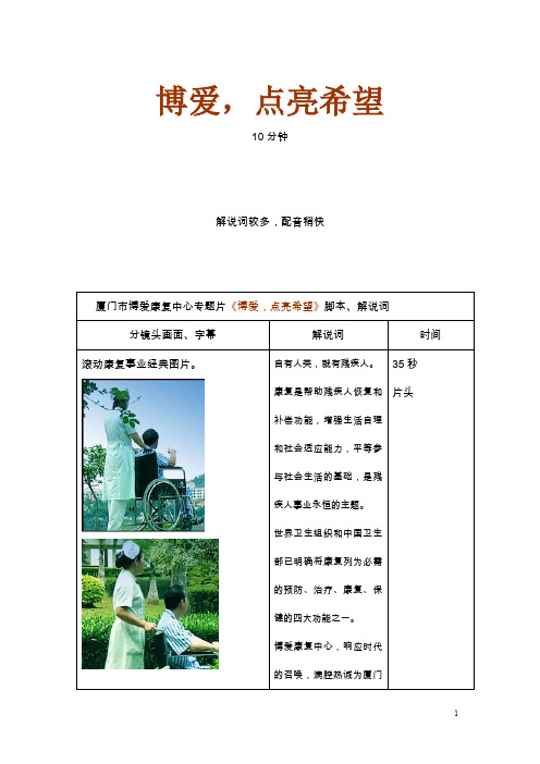
博爱康复中心,响应时代的召唤,满腔热诚为厦门市残疾人群体服务,给他们点亮一盏盏希望的灯火。
35秒
片头
康复中心外景,大门
医保(IC卡)定点单位
工伤康复协议单位
厦门市博爱康复中心,成立于2001年,是经市编委批准、市残联直接领导的事业单位,被厦门市卫生局审批为二级乙等非营利性康复专科机构,是厦门市医保定点单位、工伤康复协议单位。下设三个实体:市特需儿童援助中心,市残联康复医院,市残疾人辅具适配中心,
2009年厦门博爱康复中心经过综合评估被中国残联的长江新里程项目办公室选拔为“脑瘫引导式教育”定点康复机构,参与的脑瘫儿童康复与残疾预防项目,在2009-2011年完成50名脑瘫孩子的任务。
截止2010年12月,中心已完成了二期引导式教育。共完成25例,已有13名孩子进入正常幼儿园就读,该项目得到家长高度认可和欢迎。
设有运动治疗科、物理治疗科、作业治疗科、中医传统治疗科、语训治疗科和视力康复科等科室,可为脑瘫、偏瘫、截瘫、视力残疾患者截肢和老年慢性疾病患者提供康复治疗服务。
康复医院引进美国STORZ公司超声乳化仪、德国蔡司眼科手术显微镜、眼科A\B超、角膜曲率计等。主要开展白内障超声乳化人工晶体植入术,承担厦门市政府白内障复明的主要工作;低视力康复;弱视康复训练和验光配镜;眼底病等。目前已成功完成白内障超声乳化手术3000余例。
30秒
特需儿童援助中心招牌,环境,设备,器具。大课,单训,亲子个训教学情境。
字幕:
截止2010年上半年,中心共康复各类残疾儿童422名已有196名儿童进入正常幼儿园和普通小学就读。
特需儿童援助中心前身是创办于2003年的厦门博爱康复中心残疾儿童康复教育部。
抖音仙鹤大叔医疗科普合集

抖音仙鹤大叔医疗科普合集公司内部档案编码:[OPPTR-OPPT28-OPPTL98-OPPNN08]鹤叔医疗科普合集()灯火阑珊整()西伯利亚狼二次美化整理整理者按:2019年10月份,一个偶然的机会通过抖音关注了鹤叔,他教我们通过最简单的方式,使用最便宜、易得的药物来解决常见的皮肤问题。
不仅告诉我们治疗的方法,还解析了疾病的发病原理,使我们解除了痛苦,甚至治愈了很多久拖不愈的疑难杂症。
鹤叔说他做科普一不为名,二不图利,就是希望老百姓多些知识的储备,少些后悔。
通过鹤叔的科普,越来越多的人自己在家就解决了原本四处求医都不见好转的皮肤问题。
杏林春满,医者仁心。
鹤叔的科普如星星之火,以燎原之势在造福更多的百姓。
希望我的整理稿,如一阵清风,带着这星火传递给更多有缘人。
感恩鹤叔的无私科普,感谢鹤粉-壮壮的校对和查漏补缺!第一篇:抖音短视频科普集锦()1、鹤叔讲课一不为名,二不图利,希望老百姓少后悔:80多岁老人得带状疱疹听人说激素有危害,不用,过了治疗期疼得拿头撞墙,生不如死;十几岁的小孩激光治了跖疣不懂预防感染,差点截肢;漂亮女孩乱用化妆品,过敏后乱抹激素闹成激素依赖性皮炎。
这类事触目惊心,就因为老百姓脑子里头没有这些知识储备。
2、面部湿疹:夏天抱孩子不得当,宝宝的口水和大人的汗水混合会对宝宝的细嫩皮肤造成伤害,大人皮肤上的细菌也趁机入侵孩子的面部,接触部位不通风,刺激和细菌很容易造成面部湿疹。
解决方法:在大人的肩膀放一块干净的手巾,孩子的脸贴在手巾上,既通风又吸收汗液和口水,避免细菌入侵。
3、小儿湿疹:具备三只眼,第一只眼准确看清小孩体内毒素的眼,为什么皮肤不停出皮疹,本质是体内的毒素,其实就是一种神经介质,如果你不知道它的量就不知道用药到什么程度可以把它中和掉,不去根,所以病就要反复发;第二只眼看清皮疹的深度,深的用药强一些,浅的用药浅一些,因为外用药有副作用;第三只眼看清孩子生活中的哪些危险因素,及时避开,及时用药。
TS36.101v1.0.0

3GPP TS 36.101v1.0.0(2007-12)Technical Specification3rd Generation Partnership Project;Technical Specification Group Radio Access Network;Evolved Universal Terrestrial Radio Access (E-UTRA);User Equipment (UE) radio transmission and reception;(Release 8)The present docu ment has been developed within the 3r d Generation Partnership Project (3GPP TM) and may be further elaborated for the purposes of 3G PP. The present d ocument has not been subject to any approval process by the 3G PP Organizational Partners and shall not be implemented.This Specification is provided for fu ture development work within 3GPP only. The Organizational Partners accept no liability for any use of this Specification. Specifications and reports for implementation of the 3GPP TM system should be obtained via the 3GPP Organizational Partners' Publications Offices.KeywordsEUTRA, User Equipment (UE), radio, RF requirements3GPPPostal address3GPP support office address650 Route des Lucioles - Sophia AntipolisValbonne - FRANCETel.: +33 4 92 94 42 00 Fax: +33 4 93 65 47 16InternetCopyright NotificationNo part may be reproduced except as authorized by written permission. The copyright and the foregoing restriction extend to reproduction in all media.© 2006, 3GPP Organizational Partners (ARIB, ATIS, CCSA, ETSI, TTA, TTC).All rights reserved.ContentsForeword (6)1Scope (7)2References (8)3Definitions, symbols and abbreviations (9)3.1Definitions (9)3.2Symbols (9)3.3Abbreviations (10)4General (11)4.1Relationship between Minimum Requirements and Test Requirements (11)5Frequency bands and channel arrangement (12)5.1General (12)5.2Frequency bands (12)5.3TX–RX frequency separation (12)5.4Channel arrangement (12)5.4.1Channel spacing (12)5.4.2Channel bandwidth (13)5.4.2.1 Nominal channel bandwidth (13)5.4.2.2Additional channel bandwidth (14)5.4.3Channel raster (15)5.4.4Channel number (15)5.4.5EA RFCN (16)6Transmitter characteristics (17)6.1General (17)6.2Transmit power (17)6.2.1Maximum Output Power (MOP) (17)6.2.2UE Power class (17)6.2.3Maximum Power Reduction (MPR) (18)6.2.4Additional Maximum Power Reduction (A-MPR) (18)6.3Output power dynamics (19)6.3.1Power control (19)6.3.2Minimum output power (19)6.3.3Transmit ON/OFF power (20)6.4Control and monitoring functions (20)6.4.1Out-of-synchronization handling of output power (20)6.5Transmit signal quality (20)6.5.1Frequency Error (20)6.5.2Transmit modulation (20)6.5.2.1Error Vector Magnitude (20)6.5.2.1.1Minimum requirement (20)6.5.2.2IQ-component (21)6.5.2.2.1Minimum requirements (21)6.5.2.3In-band emissions (21)6.5.2.3.1Minimum requirements (21)6.6Output RF spectrum emissions (21)6.6.1Occupied bandwidth (22)6.6.2Out of band emission (22)6.6.2.1Spectrum emission mask (22)6.6.2.1.1Minimum requirement (22)6.6.2.2Additional Spectrum Emission Mask (23)6.6.2.2.1Minimum requirement (network signalled value “NS_03”) (23)6.6.2.2.2Minimum requirement (network signalled value “NS_04”) (23)6.6.2.2.3Minimum requirement (network signalled) (24)6.6.2.3Adjacent Channel Leakage Ratio (24)6.6.2.3.1Minimum requirement E-UTRA (24)6.6.2.3.2Minimum requirements UTRA (25)6.6.2.4Additional ACLR require ments (25)6.6.2.4.1Minimum requirements (network signalled value “NS_02”) (25)6.6.3Spurious emissions (26)6.6.3.1Minimum requirements (26)6.6.3.2Spurious emission band UE co-existence (26)6.6.3.3Additional spurious emissions (27)6.6.3.3.1Minimum requirement (network signalled value “NS_05”) (27)6.6.3.3.2Minimum requirements (network signalled) (27)6.7Transmit intermodulation (27)7Receiver characteristics (29)7.1General (29)7.2Diversity characteristics (29)7.3Reference sensitivity power level (29)7.3.1Minimum requirements (QPSK) (29)7.3.2Maximum Sensitivity Reduction (MSR) (30)7.4Maximum input level (30)7.4.1Minimum requirements (31)7.5Adjacent Channel Selectivity (A CS) (31)7.5.1Minimum requirements (31)7.6Blocking characteristics (32)7.6.1In-band blocking (32)7.6.1.1Minimum requirements (32)7.6.2Out of-band blocking (33)7.6.2.1Minimu m requirements (33)7.6.3Narrow band blocking (34)7.6.3.1Minimum requirements (34)7.7Spurious response (35)7.7.1Minimum requirements (35)7.8Intermodulation characteristics (35)7.8.1Wide band Intermodulation (35)7.8.1.1Minimum requirements (35)7.8.2Narrow band Intermodulation (36)7.8.2.1Minimum requirements (36)7.9Spurious emissions (36)7.9.1Minimum requirements (36)8Performance requirement (37)8.1General (37)8.1.1Dual-antenna receiver capability (37)8.1.1.1Simultaneous unicast and MBMS operations (37)8.1.1.2Dual-antenna receiver capability in idle mode (37)Annex A (normative): Measurement channels (38)A.1General (38)A.2UL reference measurement channels (38)A.3DL reference measurement channels (38)Annex B (normative): Propagation conditions (39)B.1General (39)B.2Propagation channel s (39)B.2.1Static propagation condition (39)B.2.2Multi-path fading propagation conditions (39)B.2.2.1Delay profiles (39)B.2.2.2Doppler spectrum (40)B.2.2.3Multi-Antenna channel models (42)B.2.2.4Combinations of channel model parameters (46)Annex C (normative): Downlink Physical Channels (47)C.1General (47)C.2Set-up (47)C.3Connection (47)Annex D (normative): Characteristics of the interf ering signal (48)D.1General (48)D.2Interference signals (48)Annex E (normative): Environmental conditions (49)E.1General (49)E.2Environmental (49)E.2.1Temperature (49)E.2.2Voltage (49)E.2.3Vibration (50)Annex F (informative): Change history (51)ForewordThis Technical Specification (TS) has been produced by the 3rd Generation Partnership Project (3GPP).The contents of the present document are subject to continuing work within the TSG and may change following formal TSG approval. Should the TSG modify the contents of the present document, it will be re-released by the TSG with an identifying change of release date and an increase in version number as follows:Version x.y.zWhere:x the first digit:1 presented to TSG for information;2 presented to TSG for approval;3 or greater indicates TSG approved document under change control.y the second digit is incremented for all changes of substance, i.e. technical enhancements, corrections, updates, etc.z the third digit is incremented when editorial only changes have been incorporated in the document.1 ScopeThe present document establishes the User Equipment (UE) minimum RF characteristics of E-UTRA for both FDD and TDD modes2 ReferencesThe following documents contain provisions which, through reference in this text, constitute provisions of the present document.∙References are either specific (identified by date of publication, edition number, version number, etc.) or non-specific.∙For a specific reference, subsequent revisions do not apply.∙For a non-specific reference, the latest version applies. In the case of a reference to a 3GPP document (including a GSM document), a non-specific reference implicitly refers to the latest version of that document in the same Release as the present document.[1] 3GPP TR 21.905[2] ETSI ETR 273: "Electromagnetic compatibility and Radio spectrum Matters (ERM); Improvement ofradiated methods of measurement (using test sites) and evaluation of the corresponding measurementuncertainties; Part 1: Uncertainties in the measurement of mobile radio equipment characteristics; Sub-part 2: Examples and annexes".[3] Recommendation ITU-R SM.329-10, “Unwanted emissions in the spurious domain”[4] Recommendation ITU-R M.1225, “Guidelines for Evaluation of Radio Transmission Technologies forIMT-2000”, ITU-R, 1997.[5] 3GPP TR 25.943 V6.0.0 (2004-12), “Deployment aspects (Release 6)”.[6] 3GPP TR 25.913: “Requirements for Evolved UTRA and UTRAN”.[7] 3GPP TS 45.005 V7.8.0 (2006-11), “3rd Generation Partnership Project; Technical Specification GroupGSM/EDGE Radio Access Network; Radio transm ission and reception (Release 7)”.[8] R4-070752, “Proposal for LTE channel models”[9] 3GPP TR 25.943 V6.0.0 (2004-12), “Deployment aspects (Release 6)”.3 Definitions, symbols and abbreviations3.1 DefinitionsFor the purposes of the present document, the following terms and definitions apply.<defined term> : <definition>.For the purposes of the present document, the terms and definitions given in TR 21.905 [x] and the following apply. A term defined in the present document takes precedence over the definition of the same term, if any, in TR 21.905 [x].Channel edge: The lowest and highest frequency of the carrier, separated by the channel bandwidth.Channel bandwidth: The RF bandwidth supporting a single E-UTRA RF carrier with the transmission bandwidth configured in the uplink or downlink of a cell. The channel bandwidth is measured in MHz and is used as a reference for transmitter and receiver RF requirements.Maximum Output Power: The mean power level per carrier of UE measured at the antenna connector in a specified reference condition.Mean power: When applied to E-UTRA transmission this is the power measured in the operating system bandwidth of the carrier. The period of measurement shall be at least one subframe (1ms) for frame structure type 1 and one subframe (0.675ms) for frame structure type 2 excluding the guard interval, unless otherwise stated.Occupied bandwidth: The width of a frequency band such that, below the lower and above the upper frequency limits, the mean powers emitted are each equal to a specified percentage β/2 of the total mean power of a given emission.Output power: The mean power of one carrier of the UE, delivered to a load with resistance equal to the nominal load impedance of the transmitter.Reference bandwidth: The bandwidth in which an emission level is specified.Transmission bandwidth: Bandwidth of an instantaneous transmission from a UE or BS, measured in Resource Block units.Transmission bandwidth configuration: The highest transmission bandwidth allowed for uplink or downlink in a given channel bandwidth, measured in Resource Block units.3.2 SymbolsFor the purposes of the present document, the following symbols apply:BW Channel Channel bandwidthF FrequencyF Interferer (offset) Frequency offset of the interfererF Interferer Frequency of the interfererF C Frequency of the carrier centre frequencyF DL_low The lowest frequency of the downlink operating bandF DL_high The highest frequency of the downlink operating bandF UL_low The lowest frequency of the uplink operating bandF UL_high The highest frequency of the uplink operating bandN DL Downlink EARFCNN Offs-DL Offset used for calculating downlink EA RFCNN Offs-UL Offset used for calculating uplink EARFCNN RB Transmission bandwidth configuration, expressed in units of resource blocksN UL Uplink EA RFCNRav M inimum average throughput per RBP Interferer Modulated mean power of the interfererΔF OOB Δ Frequency of Out Of Band emission3.3 AbbreviationsFor the purposes of the present document, the abbreviations given in TR 21.905 [1] and the following apply. An abbreviation defined in the present document takes precedence over the definition of the same abbreviation, if any, in TR 21.905 [1].ACLR Adjacent Channel Leakage RatioACS Adjacent Channel SelectivityA-MPR Additional Maximum Power ReductionAWGN Additive White Gaussian NoiseBS Base StationCW Continuous WaveDL DownlinkEA RFCN E-UTRA Absolute Radio Frequency Channel NumberE-UTRA Evolved UMTS Terrestrial Radio AccessEUTRAN Evolved UMTS Terrestrial Radio Access NetworkEVM Error Vector MagnitudeFDD Frequency Division DuplexFRC Fixed Reference ChannelHD-FDD Half- Duplex FDDMCS Modulation and Coding SchemeMOP Maximum Output PowerMPR Maximum Power ReductionMSR Maximum Sensitivity ReductionOOB Out-of-bandPA Power A mplifierREFSENS Reference Sensitivity power levelSNR Signal-to-Noise RatioTDD Time Division DuplexUE User EquipmentUL UplinkUMTS Universal Mobile Telecommunications SystemUTRA UMTS Terrestrial Radio AccessUTRAN UMTS Terrestrial Radio Access NetworkOther abbreviations used in the present document are listed in 3GPP TR 21.905 [1].4 General4.1 Relationship between Minimum Requirements and TestRequirementsThe Minimum Requirements given in this specification make no allowance for measurement uncertainty. The test specification TS 36.xxx section y defines Test Tolerances. These Test Tolerances are individually calculated for each test. The Test Tolerances are used to relax the Minimum Requirements in this specification t o create Test Requirements.The measurement results returned by the Test System are compared - without any modification - against the Test Requirements as defined by the shared risk principle.The Shared Risk principle is defined in ITU-R M.1545 [3].5 Frequency bands and channel arrangement5.1 GeneralThe channel arrangements presented in this clause are based on the frequency bands and channel bandwidths defined in the present release of specifications.NOTE: Other frequency bands and channel bandwidths may be considered in future releases.5.2 Frequency bandsE-UTRA is designed to operate in the frequency bands defined in Table 5.2-1.Table 5.2-1 E-UTRA frequency bands5.3 TX–RX frequency separation5.4 Channel arrangement5.4.1 Channel spacingThe spacing between carriers will depend on the deployment scenario, the size of the frequency block available and the channel bandwidths. The nominal channel spacing between two adjacent E-UTRA carriers is defined as following:Nominal Channel spacing = (BW Channel(1) + BW Channel(2))/2where BW Channel(1) and BW Channel(2) are the channel bandwidths of the two respective E-UTRA carriers. The channel spacing can be adjusted to optimize performance in a particular deployment scenario5.4.2 Channel bandwidthRequirements in present document are specified for the channel bandwidths listed in Table 5.4-1.Table 5.4-1 Transmission bandwidth configuration N RB in E-UTRA channel bandwidthsFigure 5.4-1 shows the relation between the Channel bandwidth (BW Channel) and the Transmission bandwidth configuration (N RB). The channel edges are defined as the lowest and highest frequencies of the carrier separated by the channel bandwidth, i.e. at F C +/- BW Channel /2.Figure 5.4-1 Definition of Channel Bandwidth and Transmiss ion Bandwidth Configuration.5.4.2.1 Nominal channel bandwidthTable 5.4.2-1 specifies the nominal channel bandwidth which are supported for the E-UTRA bandTable 5.4.2-1: E-UTRA channel bandwidth5.4.2.2 Additional channel bandwidthThe following additional channel bandwidth can be supported if certain relaxations of the UE performance are allowed or UE functionality is limited. These relaxations and limitations are TBD.Table 5.4.4.2-1: Additional E-UTRA channel bandwidth5.4.3 Channel rasterThe channel raster is 100 kHz for all bands, which means that the carrier centre frequency must be an integer multiple of 100 kHz.5.4.4 Channel numberThe carrier frequency in the uplink and downlink is designated by the E-UTRA Absolute Radio Frequency Channel Number (EA RFCN). The carrier frequency in MHz for the downlink is given by the following equation, where F DL_low and N Offs-DL are given in table 5.4.4-1 and N DL is the downlink EA RFCN.F DL = F DL_low + 0.1(N DL– N Offs-DL)The carrier frequency in MHz for the uplink is given by the following equation where F UL_low and N Offs-UL are given in table 5.4.4-1 and N UL is the uplink EARFCN.F UL = F UL_low + 0.1(N UL– N Offs-UL)Table 5.4.4-1 E-UTRA channel numbers5.4.5 EARFCN6 Transmitter characteristics6.1 GeneralUnless otherwise stated, the transmitter characteristics are specified at the antenna connector of the UE with a single transmit antenna. For UE with integral antenna only, a reference antenna with a gain of 0 dBi is assumed.6.2 Transmit power6.2.1 Maximum Output Power (MOP)The Maximum Output Power (MOP) defined in Table 6.2.1-1 is the broadband transmit power of the UE, i.e. the power in the channel bandwidth (clause 5.2) for all transmit bandwidth configurations (resource blocks).Table 6.2.1-1: Maximum Output Power (MOP)6.2.2 UE Power classThe following UE Power Classes define the nominal maximum output power. The nominal power is defined as the broadband transmit power of the UE, i.e. the power in the channel bandwidth (clause 5.2) of the radio access mode. The period of measurement shall be at least one [timeslot/ frame/TTI].Table 6.2.2-1: UE Power ClassThe transmission bandwidth configuration (resource blocks) for the maximum output power specified in Table 6.2.2-1 is defined in Table 6.2.2-2 below for QPSK modulation.Table 6.2.2-2: UE Power Class / channel bandwidth / transmission configuration6.2.3 Maximum Power Reduction (MPR)For UE PowerClass 3, the allowed Maximum Power Reduction (MPR) for the nominal maximum output power in 6.2.2 due to higher order modulation and transmit bandwidth configuration (resource blocks) is specified in Table 6.2.3-1.Table 6.2.3-1: Maximum Power Reduction (MPR) for PC 36.2.4 Additional Maximum Power Reduction (A-MPR)Additional ACLR and spectrum emission requirements can be signalled by the network to indicate that the UE shall meet also additional requirements in a specific deployment scenario. To meet these additional requirements the concept of A-MPR is introduced.For UE Power Class 3 the specific requirements and identified sub-clauses are specified in table 6.2.4-1 along with the allowed A-MPR values that may be used to meet these requirements. The allowed A-MPR values specified below are in addition to the allowed MPR requirements specified in clause 6.2.3.Table 6.2.4-1: Additional Maximum Power Reduction (A-MPR) / Spectrum Emission requirements6.3 Output power dynamics6.3.1 Power control6.3.2 Minimum output powerThe minimum controlled output power of the UE is defined as the broadband transmit power of the UE, i.e. the power in the channel bandwidth (clause 5.2) for all transmit bandwidth configurations (resource blocks), when the power is set to a minimum value.6.3.2.1Minimum requirementThe minimum output power is defined as the mean power in one sub-frame (1ms). The minimum output power shall be less than [-30] dBm.6.3.3 Transmit ON/OFF power6.4 Control and monitoring functions6.4.1 Out-of-synchronization handling of output power6.5 Transmit signal quality6.5.1 Frequency ErrorThe UE modulated carrier frequency shall be accurate to within ±0.1 PPM observed over a period of one sub-frame(1ms) for generic frame structure type 1 and one sub-frame (0.675ms) for frame structure type 2 excluding the guard period (Cyclic prefix).6.5.2 Transmit modulationTransmit modulation defines the modulation quality for expected in-channel RF transmissions from the UE. This transmit modulation limit is specified in terms of; an Error Vector Magnitude (EVM) for the allocated resources blocks (RB), an I/Q component and an in-band emissions for the non-allocated RB.6.5.2.1 Error Vector MagnitudeThe Error Vector Magnitude is a measure of the difference between the reference waveform and the measured waveform. This difference is called the error vector. Before calculating the EVM the measured waveform is corrected by the sample timing offset and RF frequency offset. Then the IQ origin offset is removed from the measured waveform.The measured waveform is further modified by selecting the absolute phase and absolute amplitude of the Tx chain. The EVM result is defined after the front-end IDFT as the square root of the ratio of the mean error vector power to the mean reference power expressed as a %. The measurement interval is one [timeslot] except when the mean power between slots is expected to change whereupon the measure ment interval is reduced by [] μs at each end of the slot. The IQ origin offset shall be removed from the evaluated signal before calculating the EVM; however, the removed relative IQ origin offset power (relative carrier leakage power) also has to satisfy the applicable requirement.6.5.2.1.1 M inimum requirementThe RMS average of the basic EVM measurements for [10 consecutive sub-frames] for the different modulations schemes shall not exceed the values specified in Table 6.5.2.1.1-1 for the parameters defined in Table 6.5.2.1.1-2.Table 6.5.2.1.1-1: Minimum requirements for Error Vector MagnitudeTable 6.5.2.1.1-2: Parameters for Error Vector Magnitude6.5.2.2 IQ-componentThe IQ origin offset is the phase and amplitude of an additive sinusoid waveform that has the same frequency as the reference waveform carrier frequency.6.5.2.2.1 Minimum requirementsThe relative carrier leakage power (IQ origin offset power) shall not exceed the values specified in Table 6.5.2.2.1-1.Table 6.5.2.2.1-1: Minimum requirements for Relative Carrier Leakage Power6.5.2.3 In-band emissions6.5.2.3.1 M inimum requirements6.6 Output RF spectrum emissionsThe output UE transmitter spectrum consists of the three components; the emission within the occupied bandwidth (channel bandwidth), the Out Of Band (OOB) emissions and the far out spurious emission domain.Figure 6.6-1: Transmitter RF spectrum6.6.1 Occupied bandwidthOccupied bandwidth is defined as the bandwidth containing 99 % of the total integrated mean power of the transmitted spectrum on the assigned channel. The occupied bandwidth for all transmission bandwidth configurations (Resources Blocks) shall be less than the channel bandwidth specified in Table 6.6.1-1Table 6.6.1-1: Occupied channel bandwidth6.6.2 Out of band emissionThe Out of band emissions are unwanted emissions immediately outside the assigned channel bandwidth resulting from the modulation process and non-linearity in the transmitter but excluding spurious emissions. This out of band emission limit is specified in terms of a spectrum emission mask and an Adjacent Channel Leakage power Ratio.6.6.2.1 Spectrum emission maskThe spectrum emission mask of the UE applies to frequencies (Δf OOB) starting from the edge of the assigned E-UTRA channel bandwidth. For frequencies greater than (Δf OOB) as specified in Table 6.6.2.1.1-1 the spurious requirements in clause 6.6.3 are applicable.6.6.2.1.1 Minimum requirementThe power of any UE emission shall not exceed the levels specified in Table 6.6.2.1.1-1 for the specified channel bandwidth.Table 6.6.2.1.1-1: General E-UTRA spectrum emission maskNote: As a general rule, the resolution bandwidth of the measuring equipment should be equal to the measurement bandwidth. However, to improve measurement accuracy, sensitivity and efficiency, the resolution bandwidth may be smaller than the measurement bandwidth. When the resolution bandwidth is smalle r than the measurement bandwidth, the result should be integrated over the measurement bandwidth in order to obtain the equivalent noise bandwidth of the measurement bandwidth.6.6.2.2 Additional Spectrum Emission MaskThis requirement is specified in ter ms of an “additional spectrum emission” requirement.6.6.2.2.1 Minimum requirement (network signalled value “NS_03”)Additional spectrum emission requirements are signalled by the network to indicate that the UE shall meet an additional requirement for a specific deployment scenario as part of the cell handover/broadcast message.When “NS_03” is indicated in the cell, the power of any UE emission shall not exceed the levels specified in Table6.6.2.2-1.Table 6.6.2.2.1-1: Additional requirements (FCC Part 22)Note: As a general rule, the resolution bandwidth of the measuring equipment should be equal to the measurement bandwidth. However, to improve measurement accuracy, sensitivity and efficiency, the resolution bandwidth may be smaller than the measurement bandwidth. When the resolution bandwidth is smaller than the measurement bandwidth, the result should be integrated over the measurement bandwidth in order to obtain the equivalent noise bandwidth of the measurement bandwidth.6.6.2.2.2 Minimum requirement (network signalled value “NS_04”)Additional spectrum emission requirements are signalled by the network to indicate that the UE shall meet an additional requirement for a specific deployment scenario as part of the cell handover/broadcast message.When “NS_04” is indicated in the cell, the power of any UE emission shall not exceed the levels specified in Table6.6.2.2.2-1.Table 6.6.2.2.2-1: Additional requirements (FCC Part 27)Note: As a general rule, the resolution bandwidth of the measuring equipment should be equal to the measurement bandwidth. However, to improve measurement accuracy, sensitivity and efficiency, the resolution bandwidth may be smaller than the measurement bandwidth. When the resolution bandwidth is smaller than the measurement bandwidth, the result should be integrated over the measurement bandwidth in order to obtain the equiv alent noise bandwidth of the measurement bandwidth.6.6.2.2.3 Minimum requirement (network signalled)6.6.2.3 Adjacent Channel Leakage RatioAdjacent Channel Leakage power Ratio (A CLR) is the ratio of the] filtered mean power centred on the assigned channel frequency to the filtered mean power centred on an adjacent channel frequency. ACLR requirements are specified for two scenarios for an adjacent E -UTRA and /or UTRA channel as shown in Figure 6.6.2.3 -1.Figure 6.6.2.3-1: Adjacent Channel Leakage requirements6.6.2.3.1 Minimum requirement E-UTRAE-UTRA Adjacent Channel Leakage power Ratio (E-UTRA ACLR) is the ratio of the filtered mean power centred on the assigned channel frequency to the filtered mean power centred on an adjacent channel frequenc y. The E-UTRA on channel and adjacent channel power is measured with a [rectangular measurement bandwidth filter.]6.6.2.3.2 Minimum requirements UTRAUTRA Adjacent Channel Leakage power Ratio (UTRA ACLR) is the ratio of the filtered mean power centred on the assigned E-UTRA channel frequency to the filtered mean power centred on an adjacent(s) UTRA channel frequency. UTRA Adjacent Channel Leakage power Ratio is specified for both the first UTRA 5 MHz adjacent channel (UTRA ACLR1) and the 2nd UTRA 5MHz adjacent channel (UTRA ACLR2) .The UTRA channel is measured with a 3.84 MHz RRC bandwidth filter with roll-off factor α =0.22. The E-UTRA channel is measured with a [rectangular measurement bandwidth filter]Table 6.6.2.3.2-1: Additional requirements6.6.2.4 Additional ACLR requirementsThis requirement is specified in terms of an additional UTRA ACLR2 requirement.6.6.2.4.1 Minimum requirements (network signalled value “NS_02”)”NS_02” is signalled by the network to indicate that the UE shall meet this additional requirement for a specific deployment scenario as part of the cell handover/broadcast message.The Additional ACLR requirements is specified for the 2nd UTRA 5MHz adjacent channel (UTRA ACLR2) .The UTRA channel is measured with a 3.84 MHz RRC bandwidth filter with roll-off factor α =0.22. The E-UTRA channel is measured with a [rectangular measurement bandwidth filter.]。
- 1、下载文档前请自行甄别文档内容的完整性,平台不提供额外的编辑、内容补充、找答案等附加服务。
- 2、"仅部分预览"的文档,不可在线预览部分如存在完整性等问题,可反馈申请退款(可完整预览的文档不适用该条件!)。
- 3、如文档侵犯您的权益,请联系客服反馈,我们会尽快为您处理(人工客服工作时间:9:00-18:30)。
GYENNO(臻络科技)宣传片
他们,一群“与时间赛跑的人”。
他们,曾经多才多艺,生活多姿多彩;
他们,家庭的顶梁柱;
他们,各自领域的佼佼者。
某一个寻常的清晨,成了人生的转折点。
帕金森,瞬间将他们推入无边的黑暗与痛苦中。
帕金森,作为中老年人常见的中枢神经系统变性疾病,已经成为继肿瘤、心脑血管病之后中老年人的“第三大杀手”。
全球帕金森病患者约450万人,中国约220万人,且每年新发病例近10万人。
多维度的运动障碍导致患者日常生活出现各种功能性障碍问题,肌肉强直,运动迟缓,静止性震颤,姿势步态异常……生活不能自理,生存质量严重下降,患者尊严受损,引发各种心理问题,家庭也倍受拖累。
帕金森病两百年前已被发现,但医学界仍然不明确这种疾病的病因和机制,存在大量的学术空白,目前除了效果有限的药物和手术治疗外,缺乏完整的解决方案以及良好的医疗体验。
GYENNO(臻络科技),有温度的市场导向学术驱动型高科技公司,致力于以科技帮助弱势人群提升生活品质,推进神经病学领域学术发展,构建基于机器人及人工智能技术的立体医疗系统,让每一位所需之人都有机会重塑身体机能。
GYENNO(臻络科技)凭借强大的专家团队卓越的技术力量,紧跟前沿科技,自主研发新型设备,搭建医疗服务平台,联合传统药企、医疗器械企业和专家学者共同为帕金森患者提供立体化、信息化完整解决方案,提高患者生活品质,提升患者治疗体验。
目前,公司成功开发“医动力”、“睿云”两套云系统和睿餐智能防抖勺、步态辅助仪两大产品。
“睿餐”智能防抖勺具有360度全方位防抖效果,可有效抵消85%以上的手部抖动,让原本不能正常进食的手抖人群进食无忧。
步态辅助仪对患者进行准确有效的感官刺激,以辅助患者克服步态症状,恢复正常行走能力。
两大产品从“手”到“脚”,从“形”到“形而上”,为帕金森病患者提供完整的“运动障碍立体解决方案”。
医动力是一款针对帕金森及运动障碍人群的慢病管理软件,能实现监测、干预、研究的远程闭环医疗体系。
通过绑定睿餐防抖勺、步态辅助仪等硬件设备,实现对患者运动症状数据的精准量化采集;
患者自主选择私人医生,私人医生可依据采集的数据及用药记录对病情进行动态监测并分析药物预后效果与病情发展,完成对患者的健康管理。
睿云-帕金森数据分析系统,基于“中国帕金森病及运动障碍疾病临床大数据库建设专家共识”,涵盖多维度临床数据录入及管理、智能查询及统计、数据分析及数据挖掘、科研课题及多中心管理等主要功能,针对不同的临床及科研需求,为医、药及学术界提供全方位的数据管理及分析服务,共同推进帕金森领域的学术发展。
让残缺的生命绽放光彩,GYENNO(臻络科技)。