tibco安装步骤说明文档
TIB_rv_Linux安装教程

TIB_rv_Linux安装教程TIB_rv_Linux安装教程Ps:以下安装教程都是在ROOT账号下,如果不用Root账号,提前赋值好权限。
1.安装前要先安装好JDK,然后将Tibco安装文件解压后上传至/usr/local2.进入/usr/local/TIB_rv_8.4.5_linux_x86 路径,给安装脚本执行权限.如果执行成功,脚本呈绿色。
命令:cd /usr/local/TIB_rv_8.4.5_linux_x86chmod +x TIBCOUniversalInstaller-lnx-x86.bin3.执行安装脚本:TIBCOUniversalInstaller-lnx-x86.bin./ TIBCOUniversalInstaller-lnx-x86.bin4.如果执行成功会出现和windows 一样的图形页面,一直下一步即可。
选择安装路径时默认/opt/tibco/tibrv/8.4/bin路径就行。
以下相关变量和该路径有关。
5.设置环境变量vim /etc/profile. 注意不要动其他的环境变量。
否则之前安装的JDK又会失效。
多个环境变量用: 隔开CLASSPATH=.:$JAVA_HOME/jre/lib/rt.jar:$JAVA_HOME/lib/d t.jar:$JAVA_HOME/lib/tools.jar:/opt/tibco/tibrv/8.4/lib/tibrvnative.jarexportPATH=$PATH:$JAVA_HOME/bin:/opt/tibco/tibrv/8.4/bin5.修改.bash_profile 文件。
vim ~/.bash_profileLD_LIBRARY_PATH=/opt/tibco/tibrv/8.4/lib:/opt/tibco/tibrv/ 8.4/lib/64 SHLIB_PATH=/opt/tibco/tibrv/8.4/libexport PATHexport LD_LIBRARY_PATHexport SHLIB_PATHexport LANG=zh_CN.utf86.安装监听。
Softing Singapore Pte Ltd 产品安装指南说明书

INSTALLATION GUIDEDisclaimer of liabilityThe information contained in these instructions corresponds to the technical status at the time of printing of it and is passed on with the best of our knowledge. The information in these instructions is in no event a basis for warranty claims or contractual agreements concerning the described products and may especially not be deemed as warranty concerning the quality and durability. We reserve the right to make any alterations or improvements to these instructions without prior notice. The actual design of products may deviate from the information contained in the instructions if technical alterations and product improvements so require.It may not, in part or in its entirety, be reproduced, copied, or transferred into electronic media.Softing Singapore Pte Ltd73 Science Park Drive#02-12/13 Cintech ISingapore Science Park 1+ 65 6569 6019+ 65 6899 1016***********************************The latest version of this manual is available in the Softing download area at: /downloadsVersion: WireXpert4500_eXport_IT_EN_I_201904© 2019 Softing Singapore Pte Ltd. In line with our policy of continuous improvement and feature enhancement, product specifications are subject to change without notice. Subject to errors and alterations. All rights reserved. Softing and the Softing logo are trademarks of Softing AG. WireXpert and the WireXpert logo are trademarks of Softing IT Networks GmbH. All other cited trademarks, product and company names or logos are the sole property of their respective owners.Table of Contents1Introduction (4)1.1 About product (4)1.2 Safety precautions (4)1.3 Intended use (5)1.4 About this document (5)1.5 System requirements (6)1.6 Other Requirements (6)2Installing and Upgrading on the PC (7)2.1 New installation (7)2.2 Upgrading from a previous version (14)2.3 Cancelling the installation wizard (16)2.4 Installation Failure Conditions (17)3Updating the device software (firmware) (18)4Declarations (20)5Related documents (23)6Technical Support (24)1 Introduction1.1 About producteXport is a software programmed to work seamlessly with WireXpert. It is designed to generate reports from test results obtained from WireXpert units or the standard OTDR *.SOR file, and capable of exporting to the commonly used *.CSV and *.PDF format for data archiving. The software has undergone numerous qualitative and functional tests to ensure the latest version meets the latest industrial standards and trend requirements.Starting from v8.0, eXport PC software implemented a new feature to allow the software to connect to eXport Cloud, a cloud-based solution to upload hierarchical label list for technicians to download, and download project files technicians uploaded from site. The conventional way of travelling up and down office to transfer data can now be done on-the-go with any Wi-Fi or mobile hotspot connection. The time spent on travelling to the office to transfer files, can now be utilized to perform more work on other projects, thus improving work productivity.This manual will only contain information and instructions on how to install eXport software. Please refer to User Manual and Guides for WireXpert for device help.1.2 Safety precautionsRead this manual before starting For damages due to improper connection, implementation or operation Softing refuses any liability according to our existing warranty obligations.Note This symbol is used to call attention to notable information that should be followed during installation, use, or servicing of this device.HintThis symbol is used when providing you with helpful user hints.CAUTION Selection of option may cause all or partial of saved data and/or settings in the device to be erased or restored to non-reversible original factory state. Backing up of saved result(s) is recommended before executing option.CAUTIONCAUTION indicates a potentially hazardous situation which, if not avoided, may result in minor or moderate injury.WARNINGWARNINGindicates a potentially hazardous situation which, if not avoided, could result in death or serious injury.DANGERDANGER indicates an imminently hazardous situation which, if not avoided, will result in death or serious injury. This signal word is to be limited to the most extreme situations.1.3 Intended useWireXpert series has been designed for use in factory, process and building control. The unit must not be used in explosion hazard areas. The permissible ambient conditions given in the Technical Data must be complied with.The faultless and safe operation of the product requires proper transport, proper storage and installation, and expert operation and maintenance in accordance with the manual.1.4 About this documentRead this manual before starting For damages due to improper connection, implementation or operation Softing refuses any liability according to our existing warranty obligations.1.4.1 Document historyDocument version Modifications compared to previous version 201702 Firmware update to v7.3 201811 Firmware update to v8.0 201904Installation updates1.4.2Conventions usedThe following conventions are used throughout Softing customer documentation:Open StartèControl PanelèPrograms Keys, buttons, menu items, commands and otherelements involving user interaction are set in boldfont and menu sequences are separated by anarrowButtons from the user interface are enclosed inPress [Start] to start the application brackets and set to bold typefaceMaxDlsapAddressSupported=23 Coding samples, file extracts and screen outputare set in Courier font typeFilenames and directories are written in italic Device description files are located inC:\<product name>\delivery\software\DeviceDescription files1.5System requirementsHardwareq PCOperating systemq Windows 7, 8.x or 10 (32 bit or 64 bit)q Intel Core 2 Duo, 2GHzq 1 GB of RAMq500 MB of free space of installationq Microsoft .NET framework 4.0 or above1.6Other Requirements1Administrator RightsAdministrator rights are required for eXport Installation.2Antivirus SoftwareAny Antivirus software running on your computer must be disabled for the entire duration of theinstallation.2 Installing and Upgrading on the PC2.1 New installation1 Download the latest eXport PC software from 2 Run eXport_setup_v8.x_x64.exe or eXport_setup_v8.x_x86.exe depending on your OS.Note Select the _x86 version if you are running 32 bits operating system (OS) and _x64 version for a 64 bits OS.3 Installation will commence after the setup file is executed.Note: If you get an error at this stage during the installation process, please refer to section 2.4 in this document.4Installation prerequisitesa.eXport requires the below components to be already present on your computer before youstart the Installation process.1.Microsoft .Net Framework 4.0 or above2.Windows Mobile Device Center3.Microsoft SQL Server Compact 3.54.Microsoft Visual C++ 2005 SP1 Redistributable5.Microsoft Visual C++ 2005 SP1 Redistributable MFC Security updateStarting from Version 8.0, the eXport Installer will run a check on the target computer for the above components before starting the Installation. If all or any of the components are missing, the user will get a screen like the one below.5Click [Install >] to install the missing components.6Please ensure that you have administrative rights to run the eXport Installer.7Please note that some components may take longer time to complete the installation. 8Once the components are installed, you will see an Interface like the one below.9Click [Next >] to proceed.10Please read and understand the License Agreement before installing the software.a.Select ‘I accept the terms in the license agreement’ and click [Next >] to proceed ORb.Select ‘I do not accept the terms in the license agreement’ to exit the installation.11You will be prompted to enter your “User Name” and “Organization Name”.Complete and click [Next >] to proceed.12Click [Change…] to change the directory of where the program will be installed, otherwise click [Next >] to proceed with the default settings.13To begin Installation, select an option from one of the two choices as shown in the interface belowa.Anyone who uses this computer (all users)b.Only for me (Current user)14If you see an error like the one below, please ignore and continue with eXport Installation.15Click [Finish] to complete and exit the installation.16Install only the 32 bit version if you are running on 32 bit operating system (OS), and 64 bit on a 64bit OS to ensure proper functioning of the software.2.2 Upgrading from a previous version1 If this is an upgrade from an earlier version from 6.x and above, you may see a message likethe one below.User Manuals For more information on installation and using eXport PC software, please refer to “Installation Guide for eXport PC software” and “User Manual for eXport PC software”.Note Softing IT Networks has ceased support for ReportXpert v5.x and earlier. Please contact *****************************************************.Note eXport 7.x has upgraded its database structure and added new features such as the Re-certification function. You are recommended to perform a clean installation of the software by uninstalling the existing 6.x software before installing the 7.x version.2 Click [Next >] to proceed.3Choose from one of the two options belowa.Repair – This option will copy the updated files to the already installed eXport directory.b.Remove – This option will remove eXport from your computer.4Click [Finish] to complete and exit the installation.2.3Cancelling the installation wizard1Installation can be cancelled any time during the installation by clicking [Cancel].Click [Yes] to cancel the installation or [No] to continue the installation.2Installation will be incomplete and eXport may cease to work or malfunction.2.4Installation Failure Conditions1.Low Disk Spacea.You will get an error message like the one below, when the available disk space on your C:\ isless than 200MB. This error will be displayed as soon as the user executes the Installer.2.Low Disk Spacea.You will get an error message like the one below, when the available disk space on your C:\ isless than the required space. This error will be displayed during the installation process.3Updating the device software (firmware)1Go to Tools èUpdate Device Firmware2Click [OK] and select USB drive from “Export to USB” window.3Click [Export] and [OK] to proceed.4Please wait while exporting takes place. This process may take a while.5Remove USB flash drive from workstation and connect to WireXpert.6 Select [Upgrade Firmware] from prompt and click [OK] button to continue.7If prompt did not appear, check thatUSB icon is present on the status bar, and press theSETUPbutton è Settings 2 è Storage è USB .8 Please wait while upgrading takes place. This process may take a while.9 Upgrade process is complete.CAUTIONSaved test results and settings may be erased during upgrading. You are recommended to save all test results before upgrading the firmware.Note – Upgrading from eXport <7.3eXport 7.x has upgraded its database structure and added new features such as the Re-certification function. You are recommended to perform a clean installation of the software by uninstalling the existing 6.x software before installing the 7.x version.Declarations 4DeclarationsThis device complies with the requirements of the EC directive 2004/108/EG "Electromagnetic Compatibility" (EMC directive). It meets the following requirements:NoteA Declaration of Conformity in compliance with the above standards has been made and can be requested from Softing Singapore Pte Ltd.China ROHSThe WireXpert device and its test components are China ROHS compliant.WEEEElectrical and electronic equipment must be disposed of separately from normal waste at the end of its operational lifetime.Please dispose of this product according to the respective national regulations or contractual agreements. If there are any further questions concerning the disposal of this product, contact Softing IT Networks.CAUTIONThis is a Class A product. In a domestic environment this product may cause radio interference. In that case the user may be required to take adequate measures!ROHSThe WireXpert device and its test components are ROHS compliant.ETL Intertek VerifiedWireXpert device is ETL verified to ANSI/TIA IIIe, IEC 61935-1 levels IIIe & IV and currently proposed Level V draft, with the applicable measurement accuracy.Class 1 Laser ProductThe light source transmitted from the following fiber test modules – Single Mode (SM), Multi-Mode (MM) and Encircled Flux compliant Multi-Mode (MMEF) are classified as Class 1 lasers and are very low risk and "safe under reasonably foreseeable use", including the use of optical instruments for intrabeam viewing.Class 1m Laser ProductThe light source transmitted from the following fiber test modules – MPO Remote are classified as Class 1m lasers and have wavelengths between302.5 nm and 4000 nm, and are safe except when used with optical aids.Related documents 5Related documentsApplication Note – E2E Link TestApplication Note – MPTLQuick Start Guide – Copper Certification TestingQuick Start Guide – Fiber Certification TestingQuick Start Guide – Encircled Flux Compliant Multimode Fiber Certification TestingQuick Start Guide – MPO Certification TestingQuick Start Guide – Digital Fiber Inspection KitUser Manual – Fiber Certification TestingUser Manual – MPO CertificationUser Manual – eXportUser Guide – List Based TestingUser Guide – Installing eXport PC SoftwareUser Guide – License UpgradeUser Guide – eXport CloudUser Guide – Custom LimitsTechnical Support 6Technical SupportSofting’s global presence ensures our customers receives sales and technical support anywhere around theworld. For more information:The AmericasSofting Inc.7209 Chapman HighwayKnoxville, TN 37920Phone: +1 865 251 5252E-mail:****************Asia / PacificSofting Singapore Pte. Ltd.73 Science Park Drive#02-12/13, Cintech ISingapore Science Park 1Singapore 118254Phone: +65-6569-6019E-mail: ********************************Softing ShanghaiRoom 416, 4/F, Mytech Intelligence Park, No.1999 East Jinxiu Road, Pudong District, 201206, Shanghai, ChinaPhone: +86 (21) 61063031E-mail: *********************************Europe/Middle East/Africa Softing IT Networks GmbH Richard-Reitzner-Alle 6D-85540 HaarPhone: +49 89 45 656 660E-mail:***************************Softing SRL87 Rue du Général Leclerc Creteil, Île-de-France 94000 ParisPhone: +33 1451 72805E-mail: ***********************Softing Italia Srl.Via M. Kolbe, 620090 Cesano Boscone (MI) Phone: +39 02 4505171E-mail:*********************AustriaBuxbaum Automation GmbH EisenstadtPhone: +43 2682 7045 60E-Mail: **********************。
Tibco 产品安装手册

TIBCO产品安装手册目录1引言 (1)1.1编写目的 (1)1.2预期读者 (1)1.3术语 (1)1.4参考资料 (1)2产品概述 (3)2.1目标 (3)2.2运行环境 (3)2.3产品架构 (3)2.3.1项目TIBCO产品简介 (4)3产品安装 (6)3.1安装TIBCO R UNTIME A GENT (6)3.1.1前置条件 (6)3.1.2安装步骤 (6)3.2安装TIBCO EMS (9)3.2.1前置条件 (9)3.2.2安装步骤 (10)3.3安装TIBCO A DMINISTRATOR (13)3.3.1前置条件 (13)3.3.2安装步骤 (13)3.4安装TIBCO B USINESS WORKS (18)3.4.1前置条件 (18)3.4.2安装步骤 (19)3.5安装TIBCO A DAPTER FOR A CTIVE D ATABASE (22)3.5.1前置条件 (22)3.5.2安装步骤 (22)3.6安装TIBCO A DAPTER FOR L OTUS N OTES (25)3.6.1前置条件 (25)3.6.2安装步骤 (26)3.7安装TIBCO A DAPTER FOR F ILES (30)3.7.1前置条件 (30)3.7.2安装步骤 (30)3.8安装TIBCO A DAPTER FOR S WIFT (33)3.8.1前置条件 (33)3.8.2安装步骤 (33)3.9安装TIBCO IPROCESS E NGINE (36)3.9.1前置条件 (36)3.9.2安装步骤 (37)3.10安装TIBCO IPROCESS M ODELER (39)3.10.1前置条件 (39)3.10.2安装步骤 (39)4技术支持 ...................................................................................................... 错误!未定义书签。
tibco rv 参数

tibco rv 参数【原创实用版】目录1.Tibco RV 简介2.Tibco RV 参数分类3.Tibco RV 参数配置方法4.Tibco RV 参数的应用实例5.Tibco RV 参数优化建议正文【Tibco RV 简介】Tibco RV(Rendezvous)是一款由 Tibco 公司开发的实时数据交换和消息传递平台。
它允许不同系统之间进行实时数据交互,支持多种数据格式和协议,广泛应用于企业级应用集成、实时数据处理和物联网等领域。
【Tibco RV 参数分类】Tibco RV 参数主要分为以下几类:1.连接参数:这些参数用于设置 Tibco RV 客户端与服务器之间的连接。
包括服务器地址、端口号、连接方式等。
2.消息参数:这些参数用于设置消息的发送和接收。
包括消息类型、消息格式、消息编码、消息大小限制等。
3.事务参数:这些参数用于设置事务处理。
包括事务方式、事务超时时间、事务隔离级别等。
4.安全参数:这些参数用于设置安全策略。
包括用户名、密码、权限等。
5.日志参数:这些参数用于设置日志记录。
包括日志级别、日志文件名、日志格式等。
6.其他参数:其他一些特定于 Tibco RV 的参数,如连接池参数、心跳检测参数等。
【Tibco RV 参数配置方法】Tibco RV 参数配置可以通过以下几种方法进行:1.配置文件:在 Tibco RV 安装目录下,有一个名为“rvconfig.properties”的配置文件,可以用文本编辑器打开并对参数进行修改。
2.命令行:在启动 Tibco RV 客户端时,可以通过命令行参数传递参数值。
例如:“rv -s host=localhost -p 7800”。
3.Tibco RV 管理界面:登录 Tibco RV 管理界面,可以在“参数配置”菜单中对相关参数进行修改。
【Tibco RV 参数的应用实例】以下是一个 Tibco RV 参数应用实例:假设有一个实时数据处理系统,需要将传感器采集到的温度数据实时传输到服务器进行分析。
TIBCO OpenSpirit Extension for ArcGIS 安装指南说明书

TIBCO OpenSpirit®Extension for ArcGIS Installation GuideArcMap Desktop Add-In Software Release 2019.0.0September 2019Important InformationSOME TIBCO SOFTWARE EMBEDS OR BUNDLES OTHER TIBCO SOFTWARE. USE OF SUCH EMBEDDED OR BUNDLED TIBCO SOFTWARE IS SOLELY TO ENABLE THE FUNCTIONALITY (OR PROVIDE LIMITED ADD-ON FUNCTIONALITY) OF THE LICENSED TIBCO SOFTWARE. THE EMBEDDED OR BUNDLED SOFTWARE IS NOT LICENSED TO BE USED OR ACCESSED BY ANY OTHER TIBCO SOFTWARE OR FOR ANY OTHER PURPOSE. USE OF TIBCO SOFTWARE AND THIS DOCUMENTIS SUBJECT TO THE TERMS AND CONDITIONS OF A LICENSE AGREEMENT FOUND IN EITHER A SEPARATELY EXECUTED SOFTWARE LICENSE AGREEMENT, OR, IF THERE IS NO SUCH SEPARATE AGREEMENT, THE CLICKWRAP END USER LICENSE AGREEMENT WHICH IS DISPLAYED DURING DOWNLOAD OR INSTALLATION OF THE SOFTWARE (AND WHICH IS DUPLICATED IN THE LICENSE FILE) OR IF THERE IS NO SUCH SOFTWARE LICENSE AGREEMENT OR CLICKWRAP END USER LICENSE AGREEMENT, THE LICENSE(S) LOCATED IN THE “LICENSE” FILE(S) OF THE SOFTWARE. USE OF THIS DOCUMENT IS SUBJECT TO THOSE TERMS AND CONDITIONS, AND YOUR USE HEREOF SHALL CONSTITUTE ACCEPTANCE OF AND AN AGREEMENT TO BE BOUND BY THE SAME. This document contains confidential information that is subject to U.S. and international copyright laws and treaties. No part of this document may be reproduced in any form without the written authorization of TIBCO Software Inc. TIBCO, OpenSpirit, and TIBCO OpenSpirit Extension for ArcGIS are either registered trademarks or trademarks of TIBCO Software Inc. in the United States and/or other countries.All other product and company names and marks mentioned in this document are the property of their respective owners and are mentioned for identification purposes only.THIS SOFTWARE MAY BE AVAILABLE ON MULTIPLE OPERATING SYSTEMS. HOWEVER, NOT ALL OPERATING SYSTEM PLATFORMS FOR A SPECIFIC SOFTWARE VERSION ARE RELEASED AT THE SAME TIME. SEE THE RELEASE NOTES FOR THE AVAILABILITY OF THIS SOFTWARE VERSIONON A SPECIFIC OPERATING SYSTEM PLATFORM.THIS DOCUMENT IS PROVIDED “AS IS” WITHOUT WARRANTY OF ANY KIND, EITHER EXPRESS OR IMPLIED, INCLUDING, BUT NOT LIMITED TO, THE IMPLIED WARRANTIES OF MERCHANTABILITY, FITNESS FOR A PARTICULAR PURPOSE, OR NON-INFRINGEMENT.THIS DOCUMENT COULD INCLUDE TECHNICAL INACCURACIES OR TYPOGRAPHICAL ERRORS. CHANGES ARE PERIODICALLY ADDED TO THE INFORMATION HEREIN; THESE CHANGES WILL BE INCORPORATED IN NEW EDITIONS OF THIS DOCUMENT. TIBCO SOFTWARE INC. MAY MAKE IMPROVEMENTS AND/OR CHANGES IN THE PRODUCT(S) AND/OR THE PROGRAM(S) DESCRIBED IN THIS DOCUMENT AT ANY TIME. THE CONTENTS OF THIS DOCUMENT MAY BE MODIFIED AND/OR QUALIFIED, DIRECTLY OR INDIRECTLY, BY OTHER DOCUMENTATION WHICH ACCOMPANIES THIS SOFTWARE, INCLUDING BUT NOT LIMITED TO ANY RELEASE NOTES AND "READ ME" FILES.Copyright © 2002-2019 TIBCO Software Inc. ALL RIGHTS RESERVED.TIBCO Software Inc. Confidential InformationiiiTable of ContentsOverview (4)Installation (6)Prerequisites (6)Installation Steps (6)Uninstall Steps (13)OverviewWith the OpenSpirit Extension, a user can extend ArcGIS functionality to allow a user to browse well, seismic, and interpretation data coming from a variety of G&G data stores and to bi-directionally share interaction events with other OpenSpirit enabled applications. Specifically this extension adds the ability to connect ArcMap to OpenSpirit in order to: •Read well, seismic, and interpretation data from OpenSpirit enabled data stores anddisplay in ArcMap•Send and receive OpenSpirit data selection events (exchange references to data with other applications)•Send and receive OpenSpirit GIS events (exchange point, polyline and polygon features with other applications)•Send and receive OpenSpirit grid events (exchange surface grids with other applications)•Send and receive OpenSpirit cursor tracking events (exchange mouse cursor x,y,z positions with other applications)•Send and receive OpenSpirit map view events (synchronize map view extents with other applications)•Send OpenSpirit map image events (synchronize map view extents with other applications and display an image of the map)•Establish a selection highlighting synchronization session (send and receive instructions to select features)InstallationPrerequisitesIn order to use the TIBCO OpenSpirit Extension for ArcGIS you must have the following applications installed on your Windows PC (running Windows 7, or Windows 10): •ArcGIS Desktop (ArcView or ArcEdit license) version 10.6 or 10.7.•OpenSpirit Runtime version 4.2.0 w/ Runtime HotFix 06 or OpenSpirit Runtime4.3.0 Installation StepsInstallation StepsThe TIBCO OpenSpirit Extension for ArcGIS is delivered as an ArcGIS Desktop Add-In.1.Download the OpenSpirit.ArcMapExtension.UI.esriAddIn file to a convenientlocation on your PC.2.Make sure the file is not blocked by right clicking on the .esriAddin file and selectingthe Unblock option if it is present.3.Install the Extension by double-clicking on the esriAddin file. This will display theESRI Add-In Utility:Then click on "Install Add-In".Your company may choose to install add-ins from a shared network drive, in which case you may just put the OpenSpirit Add-In in this directory and ArcGIS willdiscover it the next time it is run.4.Create a Windows firewall exemption rule for the ArcMap executable to enable theOpenSpirit extension to receive events.Open a Windows command window or a power shell window with administrator privilege and execute the command:netsh.exe firewall add allowedprogram program="C:\Program Files (x86)\ArcGIS\<version>\bin\ArcMap.exe" name="ArcMap"mode=ENABLE scope=ALL profile=ALLwhere <version> is the version of ArcGIS Desktop you have installed.For example, if running with ArcGIS Desktop 10.5 installed in the default location:: netsh.exe firewall add allowedprogram program="C:\ProgramFiles (x86)\ArcGIS\Desktop10.5\bin\ArcMap.exe"name="ArcMap" mode=ENABLE scope=ALL profile=ALLunch ArcGIS Desktop6.If the OpenSpirit toolbar is not visible make sure it is enabled for display bynavigating to the Customize-> Extensions menu item and make sure the toolbar isenabled for display. It should look like this:Check your ArcGIS Add-In Manager options if the OpenSpirit toolbar does not appear in the list of extensions. ArcGIS will not load the OpenSpirit Extension if the Load only ESRI provided Add-Ins option is selected on the Add-In Manager's Options tab. Use the Require Add-Ins to be digitally signed by a trusted publisher option or the Load all Add-Inswithout restrictions option. ArcMap must be restarted for the OpenSpirit Extension to appear in the extension list after changing the setting.7.The OpenSpirit toolbar should appear as a dockable toolbar like this:In order to dock it simply drag it by it's light blue header and deposit it on the arrow icon indicating where you want the toolbar docked:Toolbar docked at North of map window:Uninstall StepsThe TIBCO OpenSpirit Extension for ArcGIS is uninstalled using the ArcMap Add-In Manager. In the ArcMap menu select Customize>Add-in Manager... menu item. The Add-in Manager window will open, under the My Add-ins section, select the TIBCO OpenSpirit Extension for ArcGIS entry, finally click the Delete this Add-in button. This will uninstall the add-in.。
安装说明书:Siemens BACnet PTEC扩展I O控制器通用I O布局
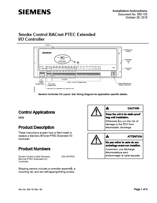
Installation InstructionsDocument No. 550-153October 26, 2016Smoke Control BACnet PTEC Extended I/O ControllerGeneric Controller I/O Layout. See Wiring Diagram for application specific details.Item No. 550-153 Rev. BA Page 1 of 6Control Applications6696Product DescriptionThese instructions explain how to field install or replace a Siemens BACnet PTEC Extended I/O Controller.Product NumbersSmoke Control Listed Siemens BACnet PTEC Extended I/O Controller550-491PKAShipping cartons includes a controller assembly, a mounting rail, and two self-tapping/drilling screws.Document No. 550-153 Installation Instructions October 26, 2016Page 2 of 6 Siemens Industry, Inc.Warning/Caution NotationAccessoriesParts for Smoke Control ComplianceSmoke Control Listed Small Equipment Controller Enclosure (Short board controllers only)540-155KSmoke Control Listed Large Equipment Controller Enclosure (Long board and ATEC controllers)550-002KUL Listed Class 2 transformer with 120/240/277/480 Vac 50/60 HZ 0.5A primary with hub and 24 Vac 96VA secondary w/ hub and circuit breakerTR100VA004NOTE:For smoke control application, primary rating is only 120V/60 Hz.Expected Installation TimeNew controller installation 10 Minutes Replacement (old controller has removable terminal blocks)6 MinutesReplacement (old controller does not have removable terminal blocks)16 MinutesNOTE:You may require additional time for database work at the field panel.Required Tools and Equipment● Small flat-blade screwdriver (1/8-inch bladewidth)● Cabling and connectors● Cordless drill/driver set● ESD wrist strapPrerequisites● Wiring conforms to NEC and local codes andregulations. For further information see the Wiring Guidelines Manual (125-3002).● Room temperature sensor installed (optional). ● 24 Vac Class 2 power available. ● Supply power to the unit is OFF.● Any application specific hardware or devicesinstalled.Document No. 550-153 Installation InstructionsOctober 26, 2016Siemens Industry, Inc. 3 of 6NOTE:If the controller is being installed on a box with 1 or more stages of electric heat, the 550-809 MOV with pre-terminated spade connectors must be installed across the manufacturer-supplied airflow switch. MOVs can be installed at the time the controller is factory mounted; coordinate with the box manufacturer prior to order placement. For field installation, seeMetal Oxide Varistor Kit Installation Instructions (540-986).NOTE:A low-cost temporary RTS (540-658P25) is available that plugs into the RTS port on the controller, providing temperature input and actual space control until a permanent RTS is installed.Installation InstructionsNOTE:All wiring must conform to national and local codes and regulations (NEC, CE, etc.).1. Secure the mounting rail in the controller’sdesired location. 2.Place the ESD wrist strap on your wrist andattach it to a good earth ground. 3. Remove the controller from the static proof bagand snap it into place on the mounting rail.4.Connect the FLN.5. Connect the point wiring (see Wiring Diagram s).6. Plug the room temperature sensor cable into theRTS port. 7. Connect the power trunk. DO NOT apply powerto the controller without first consulting the specialist. This TEC is designed to work with 2-wire AC power (Neutral and Phase (hot) at 24 Vac +/-20%. Use of the earth terminal is optional and if used it should be connected to the nearest earth ground (building steel, conduit or duct work (if earthed)).)Document No. 550-153 Installation Instructions October 26, 2016Page 4 of 6 Siemens Industry, Inc.The installation is complete.Smoke Control ComplianceThe following instructions and information apply if used for smoke control sequence.1. Install Smoke Control Listed products, enclosureand transformer (see Parts for Smoke Control Compliance section for more information). 2. Input Rating:-24V 60 HZ 60 VA3. Digital Output (DO) are the only I/O suitable forsmoke control application. Digital Output (DO) Electrical Ratings:-5VA per DO/maximum 40 VA total.4. The room temperature sensor (RTS) is installedin the same room as the TEC. 5. Connection from the TEC to the field panel is amaximum 4000 feet, 24 AWG minimum.6. Wiring Range:- Transformer: primary 14 AWG - 24 Vac Input Power: 14 to 18 AWG - DO: AI: 18 to 20 AWG - DI: 18 AWG - LAN: 20 to 24 AWG -RST: 24 AWGAll circuits are power limited; FLN is RS-485, RTS is RS-232. Digital Inputs (DI) are dry contacts. See the following documents for more information on configuring smoke control applications:● Smoke Control Systems Application andEngineering Manual (125-1806)● Smoke Control System Application Guide (125-1816)● NFPA and UL Standards Relevant to SmokeControl System Application Guide (125-1817)NOTE:The 24 Vac relay module is not applicable for smoke control application.Document No. 550-153 Installation InstructionsOctober 26, 2016Siemens Industry, Inc. 5 of 6Wiring DiagramNOTE:The controller’s DOs control 24 Vac loads only. The maximum rating is 12 VA for each DO. An externalinterposing relay is required for any of the following:• VA requirements higher than the maximum• 110 or 220 Vac requirements • DC power requirements• Separate transformers used to power the load(for example part number 540-147, Terminal Equipment Controller Relay Module)Wiring for AI with a 4 to 20 mA Sensor.NOTE:When wiring any actuator that uses a 0 to 10V control signal and ties AC neutral to DC common, an additional wire must connect the actuator AC neutral to the DC common of the PTEC/TEC AO being used to controlthe actuator.24 Vac Modulating Control.Document No. 550-153Installation InstructionsOctober 26, 2016Information in this document is based on specifications believed correct at the time of publication. The right is reserved to make changes as design improvements are introduced. Product or company names mentioned herein may be the trademarks of their respective owners. © 2016 Siemens Industry, Inc.Siemens Industry, Inc. Building Technologies Division 1000 Deerfield Parkway Buffalo Grove, IL 60089-4513 USATel. 1 + 847-215-1000Your feedback is important to us. If you havecomments about this document, please send them*****************************************.Document No.550-153Printed in the USAPage 6 of 6Application 6696 – Extended I/O Controller.*A voltage/current switch for AI 3 is located under the controller’s cover on the circuitboard (behind AI 3). It must be set either to voltage or current position according tofunction.NOTE: If the voltage/current switch is set to current and a 4 to 20 mA sensor isconnected to AI 3, then special wiring requirements must be followed. See Wiring for AI 3 with a 4 to 40 mA Sensor drawing. Cyber security disclaimer Products, solutions and services from Siemens include security functions to ensure the secure operation of building automation and control, fire safety, security management, and physical security systems. The security functions on these products, solutions and services are important components of a comprehensive security concept.Drafting, implementing and managing a comprehensive and up-to-date security concept, customized to individual needs, is nevertheless necessary, and may result in additional plant- orsite-specific preventive measures to ensure secure operation of your site regarding building automation and control, fire safety, security management, and physical security. These measures may include, for example, separating networks, physically protecting system components, user training, multi-level defensive measures, etc. For additional information on security as part of building technology and our product, solution and service offerings, please contact your Siemens sales representative or project department. We strongly recommend to always comply with our security advisories on the latest security threats, patches and other related measures. /cert/en/cert-security-advisories.htm。
Carbide3D BitSetter自动工具偏移探测器安装和设置指南说明书
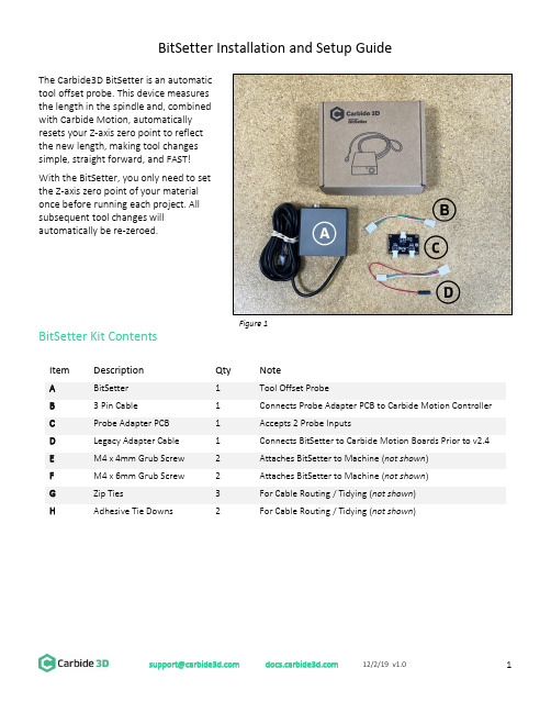
BitSetter Installation and Setup GuideThe Carbide3D BitSetter is an automatictool offset probe. This device measuresthe length in the spindle and, combinedwith Carbide Motion, automaticallyresets your Z-axis zero point to reflectthe new length, making tool changessimple, straight forward, and FAST!With the BitSetter, you only need to setthe Z-axis zero point of your materialonce before running each project. Allsubsequent tool changes willautomatically be re-zeroed.BitSetter Kit ContentsItemDescription Qty Note ABitSetter 1 Tool Offset Probe B3 Pin Cable 1 Connects Probe Adapter PCB to Carbide Motion Controller CProbe Adapter PCB 1 Accepts 2 Probe Inputs DLegacy Adapter Cable 1 Connects BitSetter to Carbide Motion Boards Prior to v2.4 EM4 x 4mm Grub Screw 2 Attaches BitSetter to Machine (not shown ) FM4 x 6mm Grub Screw 2 Attaches BitSetter to Machine (not shown ) GZip Ties 3 For Cable Routing / Tidying (not shown ) HAdhesive Tie Downs2 For Cable Routing / Tidying (not shown )Figure 1Install the BitSetterShapeoko XL/XXL InstallationThe BitSetter attaches to the front of your Shapeoko by sliding over the lip of the front end plate. The unit is secured to the machine with grub screws inserted from the rear of the BitSetter. See Figure 2. 1. Turn off your machine and unplug it. Disconnect the USB cable.2. Insert M4x4mm grub screws into the toptwo screw holes (shown in Figure 3). Juststart the screws so they are barely in thethreads.3. Slide the BitSetter over the edge of the frontend plate, about 4.5 inches (115mm) fromthe right edge of the end plate See Figure 4.4. To make sure the spindle can touch theBitSetter without interference, slowly movethe gantry (by hand) so it is directly abovethe BitSetter. Ensure the center of thespindle is in line with the center of theBitSetter. See Figure 7 below. 5. If necessary, slide your BitSetter to the rightor left along the front end plate to align the trigger with the center of your spindle.6. Once aligned, tighten the two M4x4mm screws so they press into the rail. These need only be snug,do not overtighten!NOTE: If you would prefer your BitSetter to sit higher in the Z direction, you can also install the BitSetter per the Shapeoko 3 installation instructions (see next page).Figure 3Figure 4Figure 2Shapeoko 3 InstallationThe BitSetter attaches to the front of your Shapeoko by sliding over the lip of the front end plate. The unit is secured to the machine with grub screws inserted from the rear of the BitSetter. See Figure 5.1. Turn off your machine and unplug it. Disconnect the USB cable.2. Insert two M4x6mm screws into the middle row of holes. See Figure 6.3. Tighten the screws until they hit the back wall of the BitSetter. These screws will raise your BitSetterup so that it does not rest on the worktable.4. Insert the two M4x4mm screws into the bottom holes;do not tighten them yet. See Figure 5.5. Slide the BitSetter over the lip of the front end plate,about 4.5 inches (115mm) from the right edge of theend plate.6. To make sure the spindle can touch the BitSetterwithout interference, slowly move your gantry (byhand) so it is above the BitSetter. Ensure the center ofthe spindle is in line with the center of the BitSetter.See Figure 7.7. If necessary, slide your BitSetter to the right or leftalong the front end plate to align the trigger with thecenter of your spindle.8. Once aligned, tighten the bottom two M4x4mm screws so they press into the end plate. These needonly be snug, do not overtighten!NOTE: If you are using the stock wasteboard, you can access the bottom screws using a ball-end hex key. If using additional wasteboards, you may need to remove the wasteboard to access the screws.Figure 7 Figure 6Figure 5Route the CableThe BitSetter cable is designed to route to your Carbide Motion controller one of two ways.Routing Option 1ing the cutout on the bottom of the BitSetter, route the cable under the machine, directly back tothe controller.e the included adhesive tie downs and zip ties to secure the cable to the machine. We recommendone tie down immediately behind the BitSetter and another where the wire feeds out near thecontroller.Routing Option 2ing the cutout on the bottom of the BitSetter, route the cable around the front-left side of themachine.e the included adhesive tie downs and zip ties to secure the cable to your machine. Make sure thecable is out of the way and fastened to your machine in convenient locations.Connect the BitSetter to the Controller BoardTo make installation simple, we have included a variety of adapters to allow you to connect the BitSetter without needing to cut or solder any wires.The instructions below apply to versions of the Carbide Motion boards shipped with Shapeoko:- 2.1 - 2.2- 2.3- 2.4d- 2.4eTo identify which version of the Carbide Motion board you own, look in the bottom-left corner of the PCB.Figure 8Version 2.1/2.2/2.3 (Using the Legacy Adapter Cable)1.Connect the female connector (green and white wires) to the probe pins as shown in Figure 9.2.Connect the red wire (+5V) to the upper-leftpin on the AVR PROGRAMMING label asshown in Figure 10.3.Once both wires are plugged in, your boardshould look like Figure 11.4.Connect the Legacy Adapter Cable to the portlabeled TO CARBIDE MOTION on the ProbeAdapter PCB.5.Connect the BitSetter to the port labeledTOOL PROBE on the Probe Adapter PCB.NOTE: If you also have a Carbide 3D probe, plug that into the port labeled TOUCH PROBE on the Probe Adapter PCB.Figure 9Figure 10Figure 11Version 2.4Beginning with version 2.4d of the Carbide Motion Controller PCB, the controller boards have a purpose-built port labeled RESERVED, which is intended for a touch probe.1.Connect the BitSetter:a.If you only have the BitSetter, you can plug it directly into the port labeled RESERVED asshown in Figure 12.b.If you have both the BitSetter and a Touch Probe, use the Probe Adapter PCB as shown inFigure 13.NOTE: If your 2.4d/e board is missing theRESERVED2.After your cable is routed to the Carbide Motion Controller, re-install the controller cover orenclosure. Make sure not to pinch or accidentally loosen any of the cables.Figure 12 Figure 13Set Up and Calibrate Carbide MotionWith the hardware installed, you now need to setup Carbide Motion control software to recognize and calibrate your BitSetter.Connect to Shapeoko1.Open Carbide Motion.2.Power on the Shapeoko, then click the Connect to Cutter button . See Figure 14.3.After the software connects, click the Initialize Machine button. This will begin a homing cycle. SeeFigure 15.Figure 14 Figure 15Clear Offsets and Change to Machine CoordinatesClear Offsets1. After homing completes, click Jog in the top menu bar.2. Click the Set Zero button . See Figure 16.3. On the Set Current Position screen, click the Clear All Offsets button . Then, click DONE . See Figure 17.4. Click the Position label . This will toggle the view to the machine coordinates. See Figure 18.5.Click Rapid Position , then click the SE button to move thespindle to the front-right of the machine. Once in position, clickDONE . See Figure 18.6. From the JOG screen, use the arrows on the screen (or thearrows on your keyboard) to jog the gantry so the spindle isdirectly above the BitSetter (as shown in Figure 19).Figure 16 Figure 17Figure 18Figure 19Configure the Permanent Position of the BitSetterFigure 20 Figure 211.Click Settings in the top menu bar.2.Click the Setup Shapeoko button. See Figure 20.3.Select the appropriate size Shapeoko from the Size dropdown list (Shapeoko 3, XL, XXL). SeeFigure 21.4.Select the Use Shapeoko HDZ checkbox, if you are using an HDZ.5.Select the BitSetter Probe checkbox. This will expand the window and allow you to configure thepermanent location of the BitSetter.6.With your spindle directly above the BitSetter, click the Use Current X/Y button to set the location.This will permanently save the X/Y location of your BitSetter.NOTE: If you physically change the BitSetter location, you will need to re-run this setup.7.Click the Update Shapoeko Configuration button to save the settings. CONGRATULATIONS! Your BitSetter is ready to use!********************* 12/2/19 v1.011Operating Your BitsetterThe start-up workflow using the BitSetter is as follows:1. Power on and connect to machine.2. Initialize Machine – this will begin a homing cycle.3. After the homing cycle completes, the gantry will automatically move to the front-right location and prompt you to insert a tool. Think of this as ‘homing’ the tool off set.4. After the tool is inserted or confirmed, the machine will then measure the length of the tool in the spindle.5. Once the initialization sequence is complete, you can load and run a job by using the Load File feature.Notes About Using Your BitSetter• Ensure tools are long enough to reach the BitSetter trigger button. The minimum length the tool must extend from the collet is 0.5.”• In order to instantiate a tool change and offset measurement, your CAM program must post unique tool numbers with each new tool. Carbide Create does this by default.• If you ever physically move the BitSetter, you will need to reconfigure its new location by following these instructions again.Check Out the BitSetter Installation VideoThere is also a complimentary video to go along with these installation instructions, which can be viewed at: https://youtu.be/I97XwLBmyuc .。
TIBCO BW培训 - 基础知识

TIBCO Training Course
34
Unit 4. 部署与管理
解释BW部署技术 定义运行组件和环境 描述应用部署和管理
校验工程和创建EAR 应用部署配置 流程应用的部署、管理和监控 域资源和用户管理
Steel Ren SOA Consultant TIBCO Training Course 35
Steel Ren SOA Consultant
TIBCO Training Course
31
服务生成结果
抽象WSDL
Schema Port
服务接口定义
Transport 具体WSDL
调用子流程来调用Operation
Steel Ren SOA Consultant
TIBCO Training Course
启动/停止组件 配置流程容错
(Fault-Tolerant)
域目录维护
增加或删除组件
Steel Ren SOA Consultant
TIBCO Training Course
13
Unit 2. 流程设计与测试
知识
使用TIBCO
Designer开发和测试 在BW流程中定义组件 解释资源和管理能力
定义业务服务和流程 配置Adapter 调试流程和Adapter
创建Enterprise Archive(EAR)
Steel Ren SOA Consultant
TIBCO Training Course
8
TIBCO Administrator
基于浏览器界面,用于
- 1、下载文档前请自行甄别文档内容的完整性,平台不提供额外的编辑、内容补充、找答案等附加服务。
- 2、"仅部分预览"的文档,不可在线预览部分如存在完整性等问题,可反馈申请退款(可完整预览的文档不适用该条件!)。
- 3、如文档侵犯您的权益,请联系客服反馈,我们会尽快为您处理(人工客服工作时间:9:00-18:30)。
TIBCO-安装步骤安装顺序:
1.Tibco Rendezvous (RV)
2.Tibco Runtime Agent (TRA)
3.Tibco Administrator
4.Tibco Business Work (BW)
以下是安装步骤图解说明:
安装步骤
选择 I accept the terms of the license agreement 执行下一步;
安装步骤
安装步骤
将Machine和 Hawk Cluster填写为当前主机的IP地址、Encoding编码选择为UTF-8取消Domain information stored in a Database 选项;
HTTP Prot 默认为8080,如有端口冲突可自行修改;
Shutdown Prot 默认为 8005,如有端口冲突可自行修改;
4. tibco-bw安装步骤
全部安装完成后将连接Oracle数据库的jar包()放到tibco\tpcl\\jdbc目录下。
日终流程中使用了一个java方法的jar包,需要把该jar包放到Tibco安装目录下的tibco\bw\\lib\palettes 下。
根据之前创建Domain是的配置在IE浏览器中输入之后弹出admin登录界面。
点击Domain名称进入登录界面;
输入之前设置的用户名密码点击登录进入管理界面;
选择 Application Management?All Applications;
在右上方点击New Application 选项卡;
进入上传EAR 文件的界面;
点击浏览选择本地EAR文件进行上传部署;
选好文件后点击右上方OK按钮;
勾选Deploy on save,然后点击save按钮;
查看Deployment Status都为Success状态说明已部署成功;。