TCN75A数字温度传感器中文数据手册「EasyDatasheet」
温度测量仪器说明书.pdf_1694208893.0651798

1Warning!EN61326-1EN60825-11. Safety notices Before using the thermodetector, please read the manual carefully. Do not use any solvent to clean the thermodetector. Safety symbols:Important information prompt for dangerComplies with European CE safety specificationThe instrument complies with the following standards:Do not align the laser to human eyes or reflective surface2. Notes When the ambient temperature changes in a sudden, it is required to place the thermodetector in the environment for 30 minutes , and measure when internal and external temperatures of the thermodetector coincide.Try to avoid any electromagnetic field caused by electric welding and induction heating.Do not place the thermodetector close to or on a high temperature object.Keep the thermodetector clean, and avoid dust from entering the tube.23. Appearance description1. Alarm indicator2. Liquid crystal display3. Laser control key/digital turn down key ▼4. Mode key5. Back-light/digital turn up key ▲6. Infrared sensor induction zone7. Laser indicator8. Measurement trigger 9. Battery cover4. Liquid crystal display description1: Primary display: Displays measured temperature.2: Function indication: MAX (Maximum value)3: Displays the maximum value4: Fahrenheit degree5: Centigrade degree6: Low voltage indication7: Laser indication8: Measurement indication9: Low alarming10: High alarming11: Data hold12: Radiance indication35. Measurement methods1. Set the upper limit of the instrument alarm:Press and hold the Mode key for 2 seconds, to enter instrument setting, and press MODE key to shift to alarm upper limit setting, in this case, Hi is displayed in the instrument function indication zone, and the alarm upper limit is displayed in the zone. Press ▲/▼ key to increase or decrease the alarm value, and long press ▲/▼ key to accelerate the increase or decrease of the set value.2: Set the low alarm value of the instrumentPress and hold the Mode key for 2 seconds, to enter instrument setting, and press MODE key to shift to alarm lower limit setting, in this case, Low is displayed in the instrument function indication zone, and the alarm lower limit is displayed in the zone. Press ▲/▼ key to increase or decrease the alarm value, and long press ▲/▼ key to accelerate the increase or decrease of the set value.3: Set the instrument radiancePress and hold the Mode key for 2 seconds, to enter the instrument setting, and press the MODE key to shift to the instrument radiance setting, in this case, the instrument radiance indication zone flashes. Press the ▲/▼ key to increase or decrease the radiation value, and long press the ▲/▼ key to accelerate the increase or decrease of the set value.44: Set the instrument temperature unitPress and hold the MODE key for 2 seconds, to enter the instrument setting, and press the MODE key to shift to the instrument temperature measurement unit, the unit symbol on the display flashes, and press the ▲/▼ key to change the unit symbol.5: Exit the settingPress the trigger or long press the MODE key, to exit the instrument setting.6: Turn on/off laserPress the key to turn on or off laser, and the instrument will display the laser symbol7:Turn on or off back-lightPress the key to turn on or off back-light.8: Non-contact temperature measurementAim the thermodetector at the object, and hold the trigger, to conduct continuous measurement of temperature. After displaying stably, release the trigger, and the5When holding the trigger, the secondary display of the instrument will display the maximum value of the measured temperature.When the measured value is greater than the upper limit of high alarm or the measured value is less than the lower limit of low alarm, the red alarm indicator will turn on to alarm.6. Target distance ratio (D:S ratio)The thermodetector has a certain visual angle and visual field, as shown in the following figure.The measured target Tube Light-sensitive componentIn order to guarantee the measured object fills in the visual field of the thermodetector, which means the thermodetector only "sees" the measured object rather than other objects. Larger objects may cause larger temperature measurement distances; for smaller objects, the measurement distances must be close. The ratio of measurement distance to the measured target (D:S) is 12:1, as shown in the following figure:677. RadianceThe radiance characterizes the ability of an object to radiate infrared ray. Larger radiance will lead to stronger radiation ability on the object surface.Radiance of the majority of organic matters or metal oxidized surfaces ranges between 0.85 and 0.98. The radiance of the thermodetector is 0.95 by default. During measurement, set the radiance of the instrument the same with the radiance of the measured object. During measurement, please pay attention to the impact of emissivity on measurement results.The following table is the radiance reference table.Measured surfaceRadiance Aluminum Oxidized0.2~0.4A3003alloy (oxidized)0.3A3003alloy (coarse)0.1~0.3Brass Polishing0.3Oxidized0.5 Copper Oxidized0.4~0.80.6Electrical terminalboardHastelloy0.3~0.8 Ferro-nickel Oxidized0.7~0.95Abrasive blasting0.3~0.6Electropolishing0.15Iron Oxidized0.5~0.9Rust0.5~0.7 Iron(casting)Oxidized0.6~0.95Unoxidized0.2Fusion cast0.2~0.3 Iron(casting)passivation0.9Lead Coarse0.4Oxidized0.2~0.6 Molybdenum oxidation0.2~0.68Nickel oxidation0.2~0.5 Platinum black0.9 Steel Cold rolling0.7~0.9Grinding steel plate0.4~0.6Polished steel plate0.1 ZincOxidized0.1 Asbestos0.95 Asphalt0.95 Basalt0.7 Carbon(unoxidized)0.8~0.9 Graphite0.7~0.8 Silicon carbide0.9 Ceramics0.95 Clay0.95 Concrete0.95 Cloth0.95 Glass plate0.85 Gravel0.9519LCD displayColor LCD display D:S12:18. Replacement of battery When battery is low, the battery symbol will light up, in this case, it is required to replace the battery. Open the battery cover with your hands, a nd replace with a new1.5Vx2AAA battery. Refer to the following figure:9.Technical indexes。
恒温传感器数据手册说明书
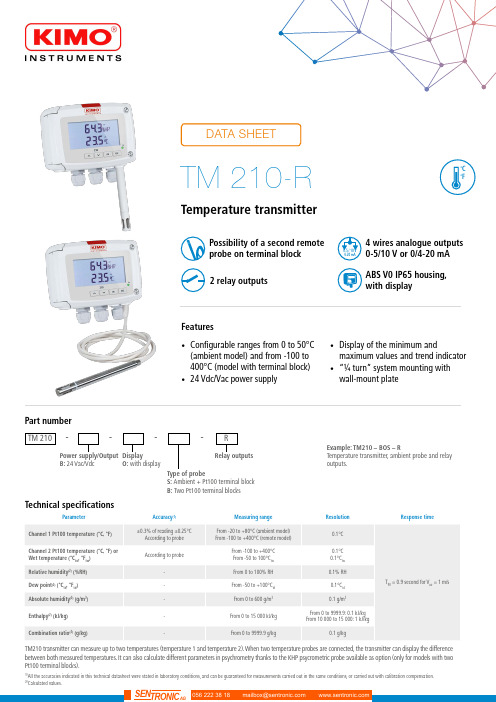
Temperature transmitter(1)All the accuracies indicated in this technical datasheet were stated in laboratory conditions, and can be guaranteed for measurements carried out in the same conditions, or carried out with calibration compensation.(2)Calculated values.Features•Configurable ranges from 0 to 50°C(ambient model) and from -100 to 400°C (model with terminal block)•24 Vdc/Vac power supply•Display of the minimum andmaximum values and trend indicator •“¼ turn” system mounting with wall-mount plate4 wires analogue outputs 0-5/10 V or 0/4-20 mA Possibility of a second remote probe on terminal block ABS V0 IP65 housing, with display2 relay outputsTM 210----Power supply/Output B: 24 Vac/Vdc Part numberDisplay O: with displayType of probeS: Ambient + Pt100 terminal block B: Two Pt100 terminal blocksExample: TM210 – BOS – RTemperature transmitter, ambient probe and relay outputs.Relay outputsRTM210 transmitter can measure up to two temperatures (temperature 1 and temperature 2). When two temperature probes are connected, the transmitter can display the difference between both measured temperatures. It can also calculate different parameters in psychrometry thanks to the KHP psycrometric probe available as option (only for models with two Pt100 terminal blocks).Warning: risk of electric shock2 x 4-20 mA or 2 x 0-20 mAor 2 x 0-5 V or 2 x 0-10 V (4 wires)DOUBLE ISOLATION ou ISOLATION RENFORCÉETechnical features of probesDifferent Pt100 temperature probes are available onthe range from -100 à +400 °C.Features of the housingAll dimensions are in millimeters.Ambient model Remote modelDimensionsPlease contact us in order to define the type of probethat corresponds to your need.ConnectiquesRelays 1 et 21234567LL+ 1. DIP switch (c)2. Pt100 n°1 terminal block3. Pt100 n°2 terminal block4. LCC-S software connection5. Relays6. Analogue outputs (a)7. Power supply terminal block (b)230 VacPeN-+0-5/10 V0/4-20 mAAf cheur régulateur ou automate type passifAf cheur régulateur ouautomate type passifSortie 4-20 mASortie 0-10 VConfiguration of the transmittersIt is possible on the class 210 to configure all the parameters of the transmitter: units, measuring ranges, outputs, channels, calculation func-tions, etc, via different methods:•Keypad for models with display: a code-locking system allows to secure the installation (See class 210 transmitters user manual).•Software (optional) on all models. Simple user-friendly configuration. See LCC-S user manual.Configurable analogue output:It is possible to configure your own intermediary rangesCaution: the minimum difference between the high range and the low range is 20.50-40 °C0 V 4 mA 0+180 °C10 V 20 mANew range-40 °C0 V 4 mA 0+180 °C10 V 20 mA50MountingTo mount the transmitter, mount the ABS plate on the wall (drilling: Ø6 mm, screws and pins are supplied).Insert the transmitter on the fixing plate (see A on the drawing beside). Rotate the housing in clockwise direction until you hear a “click” which confirms that the transmitter is correctly installed.MaintenancePlease avoid any aggressive solvent. Please protect the transmitter and its probes from any cleaning product containing formalin, that may be used for cleaning rooms or ducts.CalibrationOutputs diagnostic: With this function, you can check with a multimeter (or on a regulator / display, or a PLC / BMS) if the transmitter out-puts work properly. The transmitter generates a voltage of 0 V , 5 V and 10 V or a current of 4 mA, 12 mA and 20 mA Certificate: Class 210 transmitters are supplied with adjusting certificates. Calibration certificates are available as an option.Options and accessoriesPrecautions for usePlease always use the device in accordance with its intended use and within parameters described in the technical features in order not to compromise the protection ensured by the device.Only the accessories supplied with the device must be used.Les dimensions sont exprimées en millimètres.F T a n g – T M 210-R – 17/04/19 – R C S (24) P ér i g u e u x 349 282 095 N o n -c o n t r a c t u a l d o c u m e n t – W e r e s e r v e t h e r i g h t t o m o d i f y t h e c h a r a c t e r i s t i c s o f o u r p r o d u c t s w i t h o u t p r i o r n o t i c e .。
TMPx75温度传感器说明书

TMPx75 具有 I 2C 和 SMBus 接口的温度传感器(采用行业标准 LM75 尺寸和引脚)1 特性•TMP175:27 个地址•TMP75:8 个地址,NIST 可追溯•数字输出:与 SMBus ™、两线制和 I 2C 接口兼容•分辨率:9 至 12 位,用户可选•精度:–-40 °C 至 +125 °C 范围内为 ±1 °C (典型值)–-40 °C 至 +125 °C 范围内为 ±2 °C (最大值)•低静态电流:50μA ,0.1μA (待机)•宽电源电压范围:2.7V 至 5.5V•小型 8 引脚微型小外形尺寸 (MSOP) 封装和 8 引脚小外形集成电路 (SOIC) 封装2 应用•电源温度监控•计算机外设过热保护•笔记本电脑•手机•电池管理•办公机器•恒温器控制•环境监测和供热通风与空气调节 (HVAC)•机电器件温度TMP175 和 TMP75 内部框图T V+A1A0A23 说明TMP75 和 TMP175 器件属于数字温度传感器,是负温度系数 (NTC) 和正温度系数 (PTC) 热敏电阻的理想替代产品。
该器件无需校准或外部组件信号调节即可提供典型值为 ±1 °C 的精度。
器件温度传感器为高度线性化产品,无需复杂计算或查表即可得知温度。
片上 12 位模数转换器 (ADC) 具备低至 0.0625°C 的分辨率。
此器件提供业界通用的 LM75 SOIC-8 和 MSOP-8 外形尺寸。
TMP175 和 TMP75 与 SMBus 、两线制和 I 2C 接口兼容。
TMP175 器件可与多达 27 个器件共用一根总线。
TMP75 可与多达八个器件共用一根总线。
TMP175 和 TMP75 都具有 SMBus 警报功能。
TMP175 和 TMP75器件适用于在通信、计算机、消费类、环境、工业和仪器等各种应用中进行扩展温度测量。
Atmel AT30TK175数字温度传感器评估套件用户指南说明书

Atmel Digital Temperature Sensors Evaluation KitAtmel AT30TK175 Starter KitHardware User GuideFeatures•Four digital temperature sensor devices: •Atmel® AT30TSE002B•Atmel AT30TS75•Atmel AT30TS750•Atmel AT30TSE758•Four event LEDs•Four alarm status LEDs:•Critical, high, low, and normal•Software switchable V CC: 3.3V, 5.0V, and OFF •Power LED Contents•One Atmel AT30TK175 adapter board•One Atmel AT88Microbase AVR® base module •6-inch USB cable•18-inch extension cableIntroductionThis starter kit utilizes the Atmel AT30TK175 adapter board to allow users to experiment and develop with the AtmelAT30TSE002B, AT30TS75, AT30TS750, and AT30TSE758 digital temperature sensors.The AT30TK175 daughterboard interfaces with the Atmel AT88Microbase board (included in the kit) to provide communication to a PC via a USB interface, allowing designers to learn and experiment with the temperature sensor demonstration utility. In addition, this kit supports a modular approach, enabling the AT30TK175 daughterboard to connect directly to an Atmel STK® series AVR development platform to easily add temperature monitoring capabilities to applications.Figure 1.Atmel AT30TK175 adapter boardAlarm status LEDs1.Atmel AT30TK175STK Starter KitThe AT30TK175 is sold with the AT88Microbase to form the Atmel AT30TK175STK starter kit. For additional information on the AT88Microbase, see the “Atmel AT88Microbase Hardware User Guide.”The Atmel AT30TK175 daughterboard with the Atmel AT88Microbase moduleFigure 1-1.2.Board ConfigurationTable 2-1. Seven-bit device address2.2.10-pin Interface HeaderTable 2-1.I2C pins: SCL, SD2 Atmel AT30TK175 Starter Kit Hardware User GuideFigure 2-2.10-pin interface header orientationNote:VCC_SEL and VCC_EN are board-level options that allow users to set the board V CC to 3.3V or 5.0V and disable V CC with VCC_EN. These options are provided to allow the temperature sensor to be evaluated withboth V CC operating voltages and to evaluate the nonvolatile registers (see Section 2.3).2.3.Alarm Status LEDsTable 2-1.Alarm status LEDs2.4.V CC Enable and Select PinsTable 2-1.V CC enable and select pinsControl High Low StateVCC_EN X ON (Default)VCC_EN X OFFVCC_SEL X 3.3V (Default)VCC_SEL X 5.0VAtmel AT30TK175 Starter Kit Hardware User Guide 33.References and Further InformationSchematics, Gerber files, bill of materials (BOM), and development and demonstration software are conveniently downloadable from the Atmel website.4.EVALUATION BOARD/KIT IMPORTANT NOTICE4 Atmel AT30TK175 Starter Kit Hardware User GuideAtmel Corporation 2325 Orchard Parkway San Jose, CA 95131 USATel: (+1)(408) 441-0311 Fax:(+1)(408) 487-2600 Atmel Asia LimitedUnit 01-5 & 16, 19FBEA Tower, Millennium City 5418 Kwun Tong RoadKwun Tong, KowloonHONG KONGTel:(+852) 2245-6100Fax:(+852) 2722-1369Atmel Munich GmbHBusiness CampusParkring 4D-85748 Garching b. MunichGERMANYTel:(+49) 89-31970-0Fax:(+49) 89-3194621Atmel Japan9F, Tonetsu Shinkawa Bldg.1-24-8 ShinkawaChuo-ku, Tokyo 104-0033JAPANTel:(+81)(3) 3523-3551Fax: (+81)(3) 3523-7581© 2011 Atmel Corporation. All rights reserved. / Rev.: 8745A–DTS–5/11Atmel®, logo and combinations thereof, and others are registered trademarks or trademarks of Atmel Corporation or its subsidiaries. Other terms and product names may be trademarks of others.Disclaimer: The information in this document is provided in connection with Atmel products. No license, express or implied, by estoppel or otherwise, to any intellectual property right is granted by this document or in connection with the sale of Atmel products. EXCEPT AS SET FORTH IN THE ATMEL TERMS AND CONDITIONS OF SALES LOCATED ON THE ATMEL WEBSITE, ATMEL ASSUMES NO LIABILITY WHATSOEVER AND DISCLAIMS ANY EXPRESS, IMPLIED OR STATUTORY WARRANTY RELATING TO ITS PRODUCTS INCLUDING, BUT NOT LIMITED TO, THE IMPLIED WARRANTY OF MERCHANTABILITY, FITNESS FOR A PARTICULAR PURPOSE, OR NON-INFRINGEMENT. IN NO EVENT SHALL ATMEL BE LIABLE FOR ANY DIRECT, INDIRECT, CONSEQUENTIAL, PUNITIVE, SPECIAL OR INCIDENTAL DAMAGES (INCLUDING, WITHOUT LIMITATION, DAMAGES FOR LOSS AND PROFITS, BUSINESS INTERRUPTION, OR LOSS OF INFORMATION) ARISING OUT OF THE USE OR INABILITY TO USE THIS DOCUMENT, EVEN IF ATMEL HAS BEEN ADVISED OF THE POSSIBILITY OF SUCH DAMAGES. Atmel makes no representations or warranties with respect to the accuracy or completeness of the contents of this document and reserves the right to make changes to specifications and products descriptions at any time without notice. Atmel does not make any commitment to update the information contained herein. Unless specifically provided otherwise, Atmel products are not suitable for, and shall not be used in, automotive applications. Atmel products are not intended, authorized, or warranted for use as components in applications intended to support or sustain life.。
Jencons 产品型号及温度传感器数据表说明书
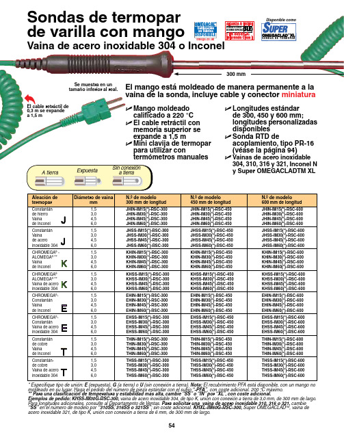
El mango está moldeado de manera permanente a la vaina de la sonda, incluye cable y conector miniatura* Especifique tipo de unión: E (expuesta), G (a tierra) o U (sin conexión a tierra). Nota: El recubrimiento PFA está disponible, con un mango no moldeado en su lugar. Haga el pedido del número de pieza estándar con el sufijo “-PFA”, con coste adicional. 200 °C máximo. ** Para una clasificación de temperatura y estabilidad más alta, cambie “SS” o “IN” por “XL ”, con coste adicional.Ejemplos de pedido: KHSS-IM30G-RSC-300, vaina de acero inoxidable 304, de tipo K, unión con conexión a tierra de 3,0 mm, de 300 mm de largo.Para longitudes adicionales, consulte al Departamento de Ventas. Para solicitar una vaina de acero inoxidable 310, 316 o 321, cambie “SS” en el número de modelo por “310SS, 316SS o 321SS”; sin coste adicional. KHXL-IM60G-RSC-300, Super OMEGACLAD TM , vaina de acero inoxidable 321, de tipo K, unión con conexión a tierra de 6 mm, de 300 mm de largo.El cable retráctil de 0,3 m se expande a 1,5 mSe muestra en un tamaño inferior al real.U M ango moldeado calificado a 220 °C U E l cable retráctil con memoria superior se expande a 1,5 m U M ini clavija de termopar para utilizar contermómetros manuales U L ongitudes estándar de 300, 450 y 600 mm; longitudes personalizadas disponibles U S onda RTD deacoplamiento, tipo PR-16 (véase la página 94)U V ainas de acero inoxidable304, 310, 316 y 321, Inconel Ny Super OMEGACLADTM XLPROBE TIPS CUTAWA Y ART PROBE TIPS CUTAWA Y ART Sondas de termopar de varilla con mangoDisponibilidad de sondas depunta especial económicas*Las calificaciones de temperatura dependen del tipo de termopar, el diámetro de la vaina y el entorno.Sonda de aireEl elemento expuesto permite el flujo de aire para una medición rápida. Calificada a 870 °C. Disponible con diámetro de 4,5 mm y unión expuesta solamente.Para hacer el pedido, añada el sufijo “-AP ” al número de modelo por un coste adicional.Ejemplo de pedido: KHSS-IM45-RSC-300-AP , sonda con mango de 300 mm de largo , tipo K, DE de 4,5 mm, vaina de acero inoxidable 304, unión expuesta, punta de sonda de aire.Nota: Disponibilidad de otros estilos, consulte Sonda de penetración (muy popular)Punta cónica, para inserción en materiales blandos y semicongelados. Calificada a 1.150 °C. Disponible con diámetro de 4,5 o 6 mm y unión con conexión a tierra solamente.Para hacer el pedido, añada el sufijo “-NP ” al número de modelo por un coste adicional.Ejemplo de pedido: KHSS-IM45-RSC-300-NP , sonda con mango de 300 mm de largo , tipo K, DE de 4,5 mm, vaina de acero inoxidable 304, unión con conexión a tierra, punta de sonda cónica.Nota: Disponibilidad de otros estilos, consulte Cable retráctilEl cable retráctil de 0,3 m se expande a 1,5 m, la clavija de termopar estándar se acopla a todos los termómetros manuales para una conexión práctica.U Large Backlit Display U Built-In IR Pyrometer Protegido por patentes estadounidenses e internacionales y solicitudes pendientes.PATENTADO¡S ond a s de t e r m o p a r c o nU S B i n c o r p or a d o ! C o n s u l t ee s .o m e g a .c o mVisite para obtener más información acerca del SUPERMETER TMMedidor manual recomendadoHHM290Sonda noincluida.。
Honeywell TX787 温度传感器说明书

may be stored in a "configuration file" on the PC for future use.After configuration, and at periodic intervals, the calibration may be veri-fied by simulating and varying the input signal over the defined range and comparing the output signal to the ideal. If calibration is necessary,the PC software is used to adjust the transmitter's digital references. Be-cause of the self-calibrating technol-ogy utilized in the TX787, the cali-bration verification interval may be significantly longer than for earlier technology transmitters.The Calibration and Configuration Software, Isolated RS232/TX787Communications Adapter and User's Guide are included in the model TX780-SOFT.by spikes and surges on field wiring entering the computer via its unpro-tected serial port.The TX787 utilize state of the art microprocessor technology and yields higher accuracy and long-term stability with lower power con-sumption than prior generation trans-mitters. The device automatically performs frequent self-testing and auto-calibration while in service, re-sulting in very stable long-term per-formance - stability greater than 0.1% of span over 12 months.To maximize traceability, each unit may be assigned a tagID, a job or a project number, the purchase order and date on which it was procured,and a message in addition to its serial number. This data, along with the selected input type and range,last calibration date, and serial num-ber are stored in the transmitter.OPERATIONEvery TX788 is factory calibrated and may be simply configured to perform the desired function using the Device Configuration screen (fig-ure 1) and the Sensor Selection screen (figure 2) shown. Just fasten the DB-9 connector to the computer's serial port and the keyed 5-pin con-nector to the port under the access cover on the top or the transmitter.There is no need to provide an ex-ternal power supply and load to the TX787's output to configure the transmitter.Units previously placed in service may have their configuration " up-loaded" to the PC. Their operating parameters may be reviewed and if necessary revised and downloaded again. All configuration parametersAPPLICATIONModel TX787 and TX788 is an ex-tremely versatile two-wire transmit-ter that may be used in any applica-tion requiring an isolated 4-20mA current loop proportional to a ther-mocouple, RTD, millivolt, milliamp,voltage, resistance or potentiometer input. Typical applications include providing accurate, stable signals to distributed control systems (DCS),supervisory control and data acqui-sition systems (SCADA), environ-mental monitoring and control sys-tems (EMCS), data acquisition and control systems (DACS) and cus-tody transfer / pipeline systems. The output of the TX787 and TX788 may also be used by an analog or digital display device.DESCRIPTIONThe TX787 is a programmable two-wire transmitter that is configured to provide an isolated 4-20mA signal in proportion to the desired range of its input signal. The TX787 accepts ther-mocouple, 2-,3-, or 4 wire RTD, po-tentiometer, and millivolt inputs. The TX788 accepts millivolt, voltage, and milliamp inputs.Configuration is performed by con-necting the transmitter to a standard PC serial port (9-pin RS232C) using an isolated interface adapter and running a user-friendly, Windows-based program. Unique PC-Only technology in the TX787 allows all configuration information to be de-fined and modified with only a PC,the interface adapter, and the trans-mitter. No loop supply, input simula-tion, or meter on the output is re-quired! The fully isolated adapter reduces the risk of expensive dam-age to the PC which can be causedTX787, TX788Programmable, Isolating Two-Wire Temperature TransmittersInstruction Sheet M-2919SPECIFICATIONS Minimum Span t/c:200C if zero offset < 6500C500C if zero offset > 6500C 1250C if zero offset > 12500C (type C only)RTD:120C if zero offset < 750C200C if zero offset < 2750C 500C if zero offset > 2750CmV:1mV if zero offset < 25mV 5mV if zero offset < 150mV 10mV if zero offset > 150mV mA:1mA if zero offset < 15mA 3mA if zero offset > 15mAVolts:0.3V if zero offset < 5V0.5V if zero offset > 5VInput ImpedenceVolts: 200k ΩMillivolts: 10m ΩMilliamps: 5Ωt/c Burnout FunctionProgrammable: upscale or downscalet/c Burnout Detection Current<0.2µARTD Excitation CurrentFilter BandProgrammable from 0 to 120%DampingProgrammable from 0.0 to 32.0secondsCommon Mode Rejection120dBOperating Temperature Range-20 to 70o CDimensions mm(inches)H 55.3 (2.10) X W 77.7 (3.06)X D 61.0 (2.40)Weight0.56lbs Warranty3 yearsLong Term StabilityBetter than 0.1% of span in 12monthsTemperature Stability<0.01% of span per 0C Isolation1000VDC input to output Minimum Output Current3.85mAMaximum Output Current22.5mALoop Voltage Drop< 9VDC at 20mA Supply Voltage Range9 - 36 VDCMaximum Effect of Change in Supply Voltage<0.002% of span per Volt Effect of Ambient Temperature Change on Cold Junction Compensation0.020C/ 0C CJC Accuracy0.50C Update Time>3 Conversions per second Turn On Time< 4 SecondsFax: (95) 203-359-7807e-mail:*****************Fax: (514) 856-6886Fax: (203) 359-7700Servicing Europe:Fax: (31) 20 6434643Fax: 49 (07056) 8540Postbus 8034, 1180 LA Amstelveen, The Netherlands Tel: (31) 20 6418405Toll Free in Benelux: 06 0993344e-mail:************Ostravska 767, 733 01 Karvina Tel: 42 (69) 6311899e-mail:***************9, rue Denis Papin, 78190 Trappes Tel:33 0130-621-400Toll Free in France: 05-4-06342e-mail:****************Daimlerstrasse 26, D-75392 Deckenpfronn, GermanyTel:49 (07056) 3017Toll Free in Germany: 0130 11 21 66e-mail:*****************25 Swannington Road,Broughton Astely, Leicestershire,LE9 6TU, England Tel: 44 (1455) 285520Fax: 44 (1455) 283912Fax: 33 0130-699-120Fax: 42 (69) 6311114P.O. Box 7, Omega Drive Irlam, Manchester,M44 5EX, England Tel: 44 (161) 777-6611Fax: 44 (161) 777-6622Toll Free in England: 0800-488-488e-mail:************976 BergarLaval (Quebec) H7L 5A1Telephone: (514) 856-6928e-mail:****************For immediate technical sevice or application assistance:Sales Service: 1-800-826-6342 / 1-800-TC-OMEGA Customer Service: 1-800-622-2378 / 1-800-622-BEST Engineering Service: 1-800-872-9436 / 1-800-USA-WHEN TELEX: 996404 EASYLINK: 62968934 CABLE: OMEGA Tel: (95) 800-TC-OMEGA En Espanol: (203) 359-1660 ext. 2203Stamford, CT 06907-0047Telephone: (203) 359-1660e-mail:**************ISO 9001 CertifiedCanada:USA and Canada:Mexico and Latin America:Benelux:Czech Republic:France:Germany/Austria:United Kingdom:ISO 9002 CertifiedRETURN REQUEST/ INQUIRIESDirect all warranty and repair requests/inquiries to the OMEGA Customer Service Department. BEFORE RETURNING ANY PRODUCT(S) TO OMEGA,PURCHASER MUST OBTAIN AN AUTHORIZED RETURN (AR) NUMBER FROM OMEGA'S CUSTOMER SERVICE DEPARTMENT (IN ORDER TO AVOID PROCESSING DELAYS). The assigned AR number should then be marked on the outside of the return package and on any correspondence.The purchaser is responsible for shipping charges, freight, insurance and proper packaging to prevent breakage in transit.FOR WARRANTY RETURNS, please have the following information available BEFORE contacting OMEGA:1.P.O. number under which the product was PURCHASED,2.Model and serial number of the product under warranty, and3.Repair instructions and/or specific problems relative to the productOMEGA is pleased to offer suggestions on the use of its various products. However, OMEGA neither assumes responsibility for any omissions or errors nor assumes liability for any damages that result from the use of its products in accordance with information provided by OMEGA, either verbal or written. OMEGA warrants only that the parts manufactured by it will be as specified and free of defects. OMEGA MAKES NO OTHER WARRANTIES OR REPRESENTATIONS OF ANY KIND WHATSOEVER,EXPRESSED OR IMPLIED, EXCEPT THAT OF TITLE, AND ALL IMPLIED WARRANTIES INCLUDING ANY WARRANTY OF MER-CHANTABILITY AND FITNESS FOR A PARTICULAR PURPOSE ARE HEREBY DISCLAIMED. LIMITATION OF LIABILITY: The rem-edies of purchaser set forth herein are exclusive and the total liability of OMEGA with respect to this order, whether based on contract, warranty, negligence, indemnification, strict liability or otherwise, shall not exceed the purchase price of the compo-nent upon which liability is based. In no event shall OMEGA be liable for consequential, incidental or special damages.CONDITIONS: Equipment sold by OMEGA is not intended to be used, nor shall it be used: (1) as a "Basic Component" under 10 CFR 21(NRC), used in or with any nuclear installation or activity; or (2) in medical applications or used on humans. Should any Product(s) be used in or with any nuclear installation or activity, medical application, used on humans, or misused in any way, OMEGA assumes no responsi-bility as set forth in our basic WARRANTY/DISCLAIMER language, and additionally, purchaser will indemnify OMEGA and hold OMEGA harmless from any liability or damage whatsoever arising out of the use of the Product(s) in such a manner.FOR NON-WARRANTY REPAIRS, consult OMEGA for current repair charges. Have the following information available BEFORE contacting O MEGA:1.P.O. number to cover the COST of the repair,2.Model and serial number of product, and3.Repair instructions and/or specific problems relative to the product.OMEGA's policy is to make running changes, not model changes, whenever an improvement is possible. This affords our customers the latest in technology and e ngineering.OMEGA is a registered trademark of OMEGA ENGINEERING, INC.ã Copyright 1996 OMEGA ENGINEERING, INC. All rights reserved. This documentation may not be copied, photocopied, reproduced, translated, or reduced to any electronic medium or machine-readable form, in whole or in part, without prior written consent of OMEGA ENGINEERING, INC.It is the policy of OMEGA to comply with all worldwide safety and EMC/EMI regulations that apply. OMEGA is constantly pursuing certification of its products to the European New Approach Directives. OMEGA will add the CE mark to every appropriate device upon certification.The information contained in this document is believed to be correct but OMEGA Engineering, Inc. accepts no liability for any errors it contains, and reserves the right to alter specifications without notice.WARNING: These product are not designed for use in, and should not be used for, patient connected applications.721-0709-00A 8/98Figure 1 Device ConfigurationFigure 2 Sensor SelectionTable 1INPUT CONNECTIONS (1) Accuracy includes input accuracy, output accuracy, andlinearity for any 2500C span within the conformance range at astable 250C ambient temperature; minimum accuracy over entireconformance range is + 0.1% of full conformance span.(2) For other RTD Types, consult Factory(3) α =.00385 and .003916(4) Percent of full scale rangeTable 2FIELD MOUNTINGThe TX787 is designed for installation in industrial field environments. A sealed, die-cast aluminum housing protects against corrosion, moisture, dust and electrical noise such as radio frequency (RFI) and electromagnetic (EMI) inter-ference. All circuit boards are urethane coated for environmental protection.。
I2C实践(一)-LM75A温度传感器_图文.
FPGA/CPLD开发套件实验教程—— PERI2-4DI 篇实验四、I 2C 实践(一)-LM75A 温度传感器实验目的:在这一课里,我们一起来学习I2C 协议,以及I2C 驱动的编写方法,并通过FPGA/CPLD来驱动LM75A 温度传感器,读出当前温度信息。
实验原理:(1 I2C串行总线概述采用串行总线技术可以使系统的硬件设计大大简化、系统的体积减小、可靠性提高。
同时,系统的更改和扩充极为容易。
常用的串行扩展总线有: I2C (Inter IC BUS )总线、单总线(1-WIRE BUS )、SPI (Serial Peripheral Interface )总线及Microwire/PLUS等。
本课仅讨论I2C 串行总线。
I2C 总线是PHLIPS 公司推出的一种串行总线,是具备多主机系统所需的包括总线裁决和高低速器件同步功能的高性能串行总线。
I2C 总线只有两根双向信号线。
一根是数据线SDA ,另一根是时钟线SCL 。
I2C 总线通过上拉电阻接正电源。
当总线空闲时,两根线均为高电平。
连到总线上的任一器件输出的低电平,都将使总线的信号变低,即各器件的SDA 及SCL 都是线“与”关系。
每个接到I2C 总线上的器件都有唯一的地址。
主机与其它器件间的数据传送可以是由主机发送数据到其它器件,这时主FPGA/CPLD开发套件实验教程—— PERI2-4DI 篇机即为发送器,总线上接收数据的器件则为接收器。
在多主机系统中,可能同时有几个主机企图启动总线传送数据,为了避免混乱, I2C 总线要通过总线仲裁,以决定由哪一台主机控制总线。
在FPGA/CPLD应用系统的串行总线扩展中,我们经常遇到的是以FPGA/CPLD为主机,其它接口器件为从机的单主机情况。
(2I2C总线的数据传送1)、数据位的有效性规定I2C 总线进行数据传送时,时钟信号为高电平期间,数据线上的数据必须保持稳定,只有在时钟线上的信号为低电平期间,数据线上的高电平或低电平状态才允许变化。
MTLx575温度传感器转换器说明书
37© 2016 EatonAll Rights ReservedPublication No.Eaton Electric Limited,Great Marlings, Butterfield, LutonBeds, LU2 8DL, UK.Tel: + 44 (0)1582 723633 Fax: + 44 (0)1582 422283E-mail:********************EUROPE (EMEA):+44(0)******************************THE AMERICAS:+********************************ASIA-PACIFIC:+*********************************The given data is only intended as a product description and should not be regarded as a legalwarranty of properties or guarantee.In the interest of further technical developments, we reserve the right to make design changes.The MTLx575 converts a low-level dc signal from a temperature sensor mounted in a hazardous area into a 4/20mA current for driving a safe-area load. Software selectable features include linearisation, ranging, monitoring, testing and tagging for all thermocouple types and 2-, 3- or 4-wire RTDs. (For thermocouple applications the HAZ-C JC plug on terminals 1–3 includes an integral CJC sensor). Configuration is carried out using a personal computer. A single alarm output is provided and may be configured for process alarm or to provide notice of early thermocouple failure.SPECIFICATIONSee also common specificationNumber of channelsOneSignal sourceTHC types J, K, T, E, R, S, B or N to BS 60584 and XKmV inputRTDs 2/3/4-wire platinum to BS 60751Pt 100, Pt 500, Pt 1000Cu-50 & Cu-53Ni 100/500/1000 DIN 43760Location of signal sourceZone 0, IIC, T4-6 hazardous areaDivision 1, Group A, hazardous locationInput signal range–75 to +75mV, or 0 to 400Ω (0 to 1000Ω Pt & Ni sensors)Input signal span3 to 150mV, or 10 to 400Ω (10 to 1000Ω Pt & Ni sensors) RTD excitation current200µA nominalCold junction compensationAutomatic or selectableCold junction compensation error≤ 1.0°CCommon mode rejection120dB for 240V at 50Hz or 60Hz (500ms response) Series mode rejection40dB for 50Hz or 60HzCalibration accuracy (at 20°C)(includes hysteresis, non-linearity and repeatability) Inputs: (500ms response)mV/THC: ± 15µV or ± 0.05% of input value(whichever is greater)RTD: ± 80mΩOutput: ± 11µATemperature drift (typical)Inputs:mV/THC: ± 0.003% of input value/°CRTD: ± 7mΩ/°COutput: ± 0.6µA/°CExample of calibration accuracy and temperature drift (RTD input - 500ms response)S pan:250ΩAccuracy: ± (0.08/250 + 11/16000) x 100%= 0.1% of spanTemperature drift: ± (0.007/250 x 16000 + 0.6) µA/°C= ±1.0µA/°CSafety drive on sensor failureUpscale, downscale, or off Early burnoutE arly burnout detection for thermocouples (when selected)Alarm trips when loop resistance increase is > 50ΩOutput range4 to 20mA nominal into 600Ω max.Alarm output (configurable)Relay ON in alarm, 250mA @ 35V maxMaximum lead resistance (THC)600ΩResponse timeConfigurable - 500 ms default(Accuracy at 100/200ms - contact MTL)LED indicatorGreen: power and status indicationYellow: alarm indication, on when contacts are closed Maximum current consumption (with 20mA signal) 50mA at 24VPower dissipation within unit (with 20mA signal)1.2W at 24VSafety descriptionRefer to certificate for parameters. Um=253V rms or dc ConfiguratorA personal computer running MTL PCS45 software with aPCL45USB serial interface.MTL4575MTL5575EPSx575 Rev4 010916。
TC系列多路温度测试仪说明书
TC系列多路温度测试仪说明书OPERATION MANUALTC系列多路温度测试仪1目录第一章快速入门 (5)1.1 前面板介绍 (5)1.2 后面板介绍 (5)1.3 按键功能描述 (6)1.4 指示灯功能描述 (6)1.5 出厂标准附件 (7)第二章技术规格 (7)主要技术参数 (7)2.12.2 补充特性 (7)第三章面板操作 (8)3.1 基本测量模式3.1.1 定点测量模式 (8)3.1.2 巡检测量模式 (8)3.2 设置操作 (8)第四章仪器通讯协议 (10)4.1 通讯设置 (10)4.2 帧格式 (10)4.3串口通讯命令字快速扫描 (11)4.4命令字的使用 (11)第五章注意事项 (16)第六章常见问题及解决方法 (16)6.1 仪器开机不能正常显示 (16)6.2 温度测量结果不对及出错 (17)2安全请勿自行在仪器上安装替代零件,或执行任何未经授权的修改。
请将仪器送回给威博科技有限公司的维修部门进行维修,以确保其安全特性。
请在购买和使用仪器前仔细参考本手册,以避免产生经济纠纷或仪器损坏。
仪器内部无操作人员可维修的部件。
若需维修服务,请联络受过训练的维修人员。
品质保证TC系列多路温度测试仪完全达到手册中所标称的各项技术指标。
售后服务威博科技有限公司承诺对本产品自购买日期起给予一年的质量保证~服务限制售后服务不适用于因以下情况所造成的损坏:顾客不正确或不适当的维修产品;未经授权的修改和误用;顾客自行安装的电路造成的损坏,或顾客使用自己的产品造成的瑕疵。
通告本手册的内容如有更改,恕不另行通知。
注意为了保证测量精度,建议开机十分钟后开始操作3简介TC系列多路温度测试仪,适用于家电、电机、电热器具等行业的制造厂家和质检部门对温度参数的测量。
为了满足用户的需求,用户可以进行如下选择:8路或16路温度测量、是否配置微型打印机。
本系列产品具有如下功能和优点: , 通过仪器设置,用户可以选择使用铜/铜镍(T型)、镍铬/镍硅(K型)或铁/铜镍(J型)热电偶, 在被测物带电的情况下,仪器可以继续测量使用, 在仪器总的巡检路数范围之内,用户可以选择任何几路进行测量 , 三种巡检速度选择:0.2S、0.4S、1.0S, 两种测量模式选择:定点、巡检, 可以设置测量温度上、下限和报警提示, 具有定时打印功能,并可以设置定时打印间隔时间(在配置微型打印机的情况下), 数字LED显示, 按键操作, 断电设定数据保持记忆功能, 错误自动检测和报警、显示闪烁提示, 可通过计算机进行软件监控附:如客户需要温控器功能,需特别声明。
omega CN7500 温度传感器产品说明书
P-23配件(可在现场安装)* 可从cn.omega .com/cn7500下载免费CN7-A 软件订购示例:CN7523,双输出控制器,DC 脉冲和机械式继电器 RS485通讯功能。
CN7500系列温度/过程控制器的高级控制功能能够应对最艰巨的温度或过程应用。
CN7500控制器封装在紧凑型1⁄32 DIN 外壳中,它配备两个4位数字LED 显示屏,可在本地显示过程值和设定值。
控制方法有开/关、PID 、自动调谐和手动调谐。
64种温度和时间(斜坡/恒值)控制措施为PID 控制提供支持。
双回路输出控制允许同时进行加热和冷却。
可将第二个输出配置成使用13种内置报警功能中其中一种的报警模式。
RS485通讯功能为标配。
可提供多达247个通讯地址,传输速度达到2400 ~ 38,400 bps 。
其它功能包括通用输入、可选温度单位(°C/°F)、可选分辨率、高采样率以及安全保护功能。
U 两个4位数字LED 显示屏U 8个斜坡/恒值程序,每个程序8段U 通用输入信号U 自动调谐U 双控制输出U 标配RS485通讯功能U 具备报警功能U 提供免费软件CN7500系列1⁄32 DIN 斜坡/恒值 控制器规格输入:热电偶、RTD 、DC 电压或DC 电流显示屏:两个4位数字、7段式6.35 mm (25")高LED ; PV :红色 SV :绿色精度:量程的±0.25%,±1最低有效数位电源电压:100 ~ 240 Vac ,50/60 Hz 功耗:最大5 VA工作温度:0 ~ 50°C (32 ~ 122°F)备用存储器:非易失性存储器额定控制输出:继电器:SPST ,5A @ 250 Vac (电阻性) 电压脉冲:14 V ,10 ~ -20%(最大40 mA )电流:4 ~ 20 mA通讯:RS485 MODBUS ® A-5-11/RTU 通讯协议重量:114 g (4 oz)面板开孔:45 x 22.5 mm (1.772 x 0.886")最大面板厚度:3.40 mm (0.14")面板厚度:99.80 mm (3.86")。
- 1、下载文档前请自行甄别文档内容的完整性,平台不提供额外的编辑、内容补充、找答案等附加服务。
- 2、"仅部分预览"的文档,不可在线预览部分如存在完整性等问题,可反馈申请退款(可完整预览的文档不适用该条件!)。
- 3、如文档侵犯您的权益,请联系客服反馈,我们会尽快为您处理(人工客服工作时间:9:00-18:30)。
热响应 响应时间
VDD
2.7
—
5.5
V
IDD
—
200
500
µA 连续工作
ISHDN
—
0.1
2
µA 关断模式
VPOR
—
1.7
—
V VDD 下降沿
TACY TACY TACY
—
±0.5
—
-3.0
—
+3.0
—
±1.5
—
°C VDD = 3.3V °C VDD = 3.3V °C VDD = 3.3V
100
50 -55 -35 -15 5
25 45 65 85 105 125 TA (°C)
图 2-5:
电源电流——环境温度曲线
Temperature Accuracy (°C)
3.0
Resolution
2.0
11-Bit
1.0
12-Bit
0.0
VDD = 3.3V 160 Samples
-1.0
-2.0
2005 Microchip Technology Inc.
DS21935A_CN 第 1 页
中文手册全文下载
TCN75A
1.0 电气特性
绝对最大额定值 †
VDD....................................................................... 6.0V 所有输入 / 输出引脚上的电压 .....GND - 0.3V 至 5.5V 存储温度 ............................................ -65°C 至 +150°C 通电时的环境温度 ............................. -55°C 至 +125°C 结温 (TJ)......................................................... 150°C 所有引脚上的 ESD 保护 (HBM:MM)...... (4 kV:400V) 每个引脚上的闭锁电流 .................................. ±200 mA
† 注:如果器件运行参数超过上述各项最大额定值,即可能对 器件造成永久性损坏。上述数值为运行条件最大值,我们不建 议器件在该规范范围外运行。如果器件长时间在绝对最大额定 条件下工作,其稳定性会受到影响。
直流特性
电气规范:除非另有说明, VDD = 2.7V 至 5.5V, GND = 地, TA = -40°C 至 +125°C。
中文手册全文下载
TCN75A
双线串行温度传感器
特性
• 温度 - 数字转换器 • 12 位分辨率时的精度:
- +25°C 时,为 ±0.5°C (典型值) - +25°C 至 +100°C 时,为 ±3°C (最大值) • 用户可选分辨率:9 – 12 位 • 工作电压范围:2.7V 至 5.5V • 双线接口:兼容 I2C™ • 工作电流:200 µA (典型值) • 关断电流:2 µA (最大值) • 节能的单次温度测量 • 封装形式:MSOP-8, SOIC-8
TCN75A
概述
Microchip Technology Inc. 的 TCN75A 数字温度传感器 将 -40°C 到 +125°C 范围内的温度转换为数字字,精度 为 ±1.5°C (典型值)。
TCN75A 产品带有用户可编程寄存器,可灵活用于各种 温度检测应用中。用户可选择寄存器设置,允许选择 9 位到 12 位的温度测量精度,省电关断模式和单次测量 模式 (在关断模式下根据命令进行单次转换)配置,以 及温度警告输出和温度迟滞限制参数。当温度变化超过 规定限制时,TCN75A 输出一个警告信号。用户可设置 警告输出信号的极性 (低电平有效或高电平有效),用 作温控器工作的比较器输出或基于微处理器系统的温度 事件中断输出。
—
—
0.4
V IOL= 3 mA
IOH
—
—
1
µA VOH = 5V
IOL
6
—
—
mA VOL = 0.6V
CIN
—
10
—
pF
迟滞
VHYST 0.05 VDD —
—
V
条件
图形符号描述
电压
输入
VDD
VIH
VIL 时间
电流
IIN 时间
电压 VDD VOL
电流 IOL
IOH
输出 时间 时间
温度特性
电气规范:除非另有说明, VDD = +2.7V 至 +5.5V 且 GND = 地。
—
1.4
—
s 从 27°C (空气)升到 125°C (油槽)过程中,达 到 63% (89°C)的时间
DS21935A_CN 第 2 页
2005 Microchip Technology Inc.
中文手册全文下载
TCN75A
数字输入 / 输出引脚特性
电气规范:除非另有说明, VDD = 2.7V 至 5.5V, GND = 地, TA = -40°C 至 +125°C。
典型应用
• 个人电脑和服务器 • 硬盘驱动器和其他 PC 外设 • 娱乐系统 • 办公设备 • 数据通信设备 • 通用温度监测设备
典型应用
VDD
PICmicro®
单片机
R
SDA
I/O 端口 SCLK
ALERT
RPULL-UP
VDD
1 SDA VDD 8 2 SCLK A0 7
3 ALERT A1 6 4 GND A2 5
5 lots 32 Samples/lot
160 Samples
图 2-4: TA = +25°C
Temperature Accuracy (°C)
温度精度柱状图,
IDD (µA)
400
350 300 250
VDD = 2.7V VDD = 3.3V
VDD = 5.0V VDD = 5.5V
200
150
参数
符号
最小值
典型 值
温度范围
规定温度范围 工作温度范围 存储温度范围 封装热阻
TA
-40
—
TA
-40
—
TA
-65
—
热阻, 8 引脚 SOIC
θJA
—
163
热阻, 8 引脚 MSOP
θJA
—
206
注 1: 在此范围内工作, TJ 不能超过最大结温 (+150°C)。
最大值
+125 +125 +150
参数
符号 最小值 典型值 最大值 单位
条件
双线 I2C™ 兼容接口
串行端口频率
fSC
0
— 400 kHz
时钟周期
tSC
2.5
—
—
µs
时钟低电平时间
tLOW
1.3
—
—
µs
时钟高电平时间
tHIGH
0.6
—
—
µs
上升时间
tR
20
—
300
ns VDD 的 10% 到 90%(SCLK,SDA)
下降时间
tF
20
2005 Microchip Technology Inc.
中文手册全文下载
TCN75A
2.0 典型性能曲线
注:
以下图表来自有限数量样本的统计结果,仅供参考。所列出的性能特性未经测试,我们不作保证。一些图 表中列出的数据可能超出规定的工作范围 (如:超出了规定电源电压范围),因此不在担保范围。
图 2-1:
平均温度精度——环境温度
曲线, VDD = 3.3V
Temperature Accuracy (°C)
3.0
2.0 VDD = 2.7V
VDD = 3.3V
1.0 VDD = 5.0V
VDD = 5.5V
0.0
12-Bit Resolution 160 Samples
-1.0
-2.0
-3.0 -55 -35 -15 5 25 45 65 85 105 125 TA (°C)
参数
符号 最小值 典型值 最大值 单位
条件
电源电压 工作电压范围 工作电流 关断电流
上电复位 (POR)阀值 温度传感器精度 12 位分辨率时的精度:
TA = +25°C +25°C < TA ≤ +100°C -40°C < TA ≤ +125°C 内部 Σ-∆ ADC 转换时间: 9 位分辨率 10 位分辨率 11 位分辨率 12 位分辨率 警告输出 (漏极开路) 高电平电流
9-Bit 10-Bit
-3.0 -55 -35 -15 5
25 45 65 85 105 125 TA (°C)
图 2-3:
平均温度精度——环境温度
曲线, VDD = 3.3V
ISHDN (µA)
1
0.8
0.6
0.4 0.2
0 -55 -35 -15 5 25 45 65 85 105 125 TA (°C )
— —
单位
°C 注 1 °C °C
°C/W °C/W
条件
2005 Microchip Technology Inc.
DS21935A_CN 第 3 页
中文手册全文下载
TCN75A
串行接口时序规范