AUTOMODE 课件
AutoMod基本操作

AutoMod學生版與專業版之切換 (3/3
)
底下的License Server的對話視窗中,只要輸入License Server Name即可;若點選Password Version則會出現輸入授權碼 (Authorization Codes)的對話視窗,使用者需根據購買專業版時, 公司所給予的授權碼輸入textbox中,並檢查其checksum與所附的是 否相同,若有不同一定是輸入錯誤所致。若點選學生版則會自動進入 AutoMod,但會有學生版使用上的限制。
刪 除
AutoMod學生版與專業版之切換 (2/3
)
在上面的Authorization視窗,我們可以根據需求點選所 要設定的版本。例如若要設定為單機專業版則點選 Password Version,若要定義為Server專業版則點選 License Server,若要定義為學生版則點選Student Version即可。
第二節 AutoMod基本架構
Auto Mod
檔案 程序 子 系統 系統 系
統
執行 分析 系統 系統
子系 自系 路統 輸系 天機 橋存 管
模統 動統 線 送統 車系 式槽 線
式
倉 儲
移 動
帶 系
系統 統
起 重系 統
與 儲
第三節 AutoMod基本概念
程序系統(Process System) 搬運系統(Movement System) Loads 擺放Loads的區域(Territory)和空間
關閉AutoMod (1/2)
關閉AutoMod (2/2)
AutoMod學生版限制 (1/4)
在AutoMod的學生版中建構模式會有實 體上的限制,一個模式中實體不能超過 200個,而11.0版以前的版本限制為100 個,這些實體指的就是如人員、設備、 儲存區等等。
AutoMod基本操作教学内容

項則所有實體都將變成線框架構(Wire-frame)。 Friction:勾選此項,當你在調整調整圖形大小或旋轉圖形時,滑
鼠放開改變即停止,反之若清除此項,當你在調整調整圖形大小 或旋轉圖形時,必須按空白鍵或去勾選Friction選項,其改變動作 才會停止。
執行模式 (2/3)
執行模式視窗分成三個部分
模擬視窗
此視窗顯示出模式的佈置(layout)並以3-D動畫方式呈現。
狀態視窗(status)
此視窗顯示出目前模擬時間及模擬狀態是處於中斷或正在進行 中。
訊息視窗(message)
此視窗顯示出關於此模式執行過程中的輸出或錯誤的訊息。
AutoMod
AutoMod
The End
AutoMod
AutoMod環境
在整個AutoMod軟體中,主要可分成兩個環境:
編輯環境 提供使用者建構模式的環境及各項參數的設定。
模擬環境 可利用模擬環境進行模擬以獲得相關的統計資料, 並將模式以動畫方式呈現。
AutoMod
執行模式 (1/3)
AutoMod
AutoMod
第四節 範例練習 (2/2)
在建模完成後,以Run Control設定模擬8小時,分 析:
文件查核區域的使用效率(Util) 將卸貨停車區空間由改為2及6,並記綠各別的使用效
率(Util)、平均數量(Average)、平均卸貨時間(Av_Time) 及平均等待時間(Av_Wait)。
AutoMod
第四節 範例練習 (1/2)
模組一:AutoMod的簡介 - 建構你的第一個 AutoMod模式
第一章模拟与Automod模拟软体

AutoMod
Step3 資料收集
(2ห้องสมุดไป่ตู้2)
輸入的資料包含:
歷史資料(historical data)
模擬政策(policies) 隨機程序與資料(random) 常數(constant)
資料的定義更要明確,譬如停機時間是否包括設備修理時
間、而設備修理時間是否也包括等待物料及修理人員的時
使用統計分析去獲得模式正確的結果。
AutoMod
Step10 模式額外的執行
根據模擬完成後的分析,決定是否需要增加額外
的運轉測試,而這些額外的測試可能必須再重新
設計模式的某一部份,並回步驟八的實驗設計階
段,重新定義實驗設計的內容。
AutoMod
Step11 書面報告整理
將結果以書面方式紀錄下來,可在未來參酌或修改模式時,
AutoMod
Step12 模式結果的執行
最後執行階段的成功端賴前述十一項步驟的實施
的程度,若最終使用者在模式建立階段能參與並
了解模式本身的特性與結果,則模式執行階段的
構的模式,是否能真實描繪出實際系統的特性與
彼此之間行為。確認模式的專業人員必須評估模
擬的程序 (procedures) 與語法 (algorithms) ,是否能
適當表達出模式定義範圍內所模擬的系統的行為。
AutoMod
Step8 實驗設計
經過模式驗證與確認的步驟後,我們即可設計適
當的實驗程序以分析系統的行為與結果。其中系
AutoMod
第一節 模擬基本概念
(5/5)
AutoMod 雖然建模的過程是以圖示的方式來建構,
无人驾驶的英语课件PPT

Other potential applications include long haul trucking, public transportation, and even self driving taxis or shared mobility services
3D Reconstruction
The creation of a 3D model of the environment from sensor data to provide more accurate representation of the scene
Path planning technology
Application scenarios for autonomous driving
Autonomous driving has the potential to revolutionize transportation, particularly in urban areas where traffic congestion and pollution are major issues
Techniques used to regulate the vehicle's velocity, acceleration, and steel angle to achieve desired performance and safety standards
Risk Assessment
The evaluation of potential hazards and their associated risks to inform decision making processes
专业版与学生版(AUTOMOD automod)
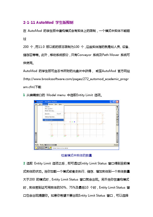
2-1-11 AutoMod 学生版限制在 AutoMod 的学生版中建构模式会有实体上的限制,一个模式中实体不能超过200 个,而11.0 版以前的版本限制为100 个,这些实体指的就是如人员、设备、储存区等等。
此外,移动系统部分,只有Conveyor 系统及Path Mover 系统可供使用。
AutoMod 的学生版可由本书所附的光盘片中获得,或至AutoMod 官方网站(/pages/272_automod_academic_program.cfm)下载1 从编辑接口的 Model menu 中选取Entity Limit 选项。
检查模式中实体的数量2 选取 Entity Limit 选项之后,即可透过Entity Limit Status 窗口得到目前模式实体的状态。
当你加载一个模式或者去执行、储存、增加实体到一个实体数量大于200 的模式时,Entity Limit Status 窗口就会出现。
另外当你在建构模式时,实体若到达可用实体的50%、75%及最后10 个时,Entity Limit Status 窗口也会出现提醒你。
如果你希望不要出现Entity Limit Status 窗口,可以选择Disable Warnings 的选项来关闭它。
模式中实体限制状态除此之外,这些实体会根据其本身之特性,被分类于不同的系统,如输送带系统、搬运系统等等。
因此为了得到更详细的实体数据,可以选择Show Entity Allocation 的选项来得到相关信息。
实体分类2-1-12 AutoMod 学生版与专业版之切换在某些情况下,我们会有学生版与专业版之间切换的需求,譬如:原先已安装了学生版,但因为已购买专业版而想改成专业版因教学需要,专业版数目不足而需改为学生版要将网络Server 专业版改为单机专业版要将单机专业版改为网络Server专业版我们可以不用重新安装而透过底下所介绍的小技巧来达成。
AUTOMODE 课件

1.6 Process 的概念
每个模型有且只有1个Process系统 进程系统定义了货物在模型中的执行逻辑 每个Process系统会有很多Processes 进程是 逻辑子系统,定义了货物(load)的一系列活 动 注意.可以形象理解 Processes是 Process系统的逻辑子系统 Processes的命名应该是唯一的,所以建议使用“P”作为首 字母命名,如: P_start,P_inspection,P_paint 模型中的每个进程都有arriving procedure,此程序要在 source file 中定义
物流仿真
2011-9-8
12
1.9 新建AutoMod模型
步骤1:启动Automod 步骤2:菜单,Model New,选择模型保存目录,键 入要新建的模型名字(如Model1),保存; 注意. Save和Export模型的区别 Export 导出 :会产生或更新modelname.arc的目录 Save 保存 :会产生或更新modelname.dir的目录
AutoMod 软件学习
2011-9-8
物流仿真
1
第一讲 AutoMod 基本操作
AutoMod操作 作业模型与系统(Models & Systems) 进程(Process)的概念 实体(Loads) 和 实体类型(Load Types) 域( Territories )的概念 使用BEdit编写逻辑定义文件 语法Syntax 运行控制
2011-9-8 物流仿真 28
1.15 随机分布 Statistical Distributions
常见的分布: 常数Constant wait for 5 min 均匀分布Uniform wait for uniform 5,1 min 正态分布Normal wait for normal 5,1 min 三角分布Triangular wait for triangular 4,5,6 min 指数分布Exponential wait for exponential 5 min
自动设置模式说明书

•Press the button to display [A1L].pressure.(When OUT1 setting is not necessary, press the and buttonsbutton to display [AP2].5, Preparation and setting of OUT2 device•Prepare the sensor for which OUT2 is to be set, and perform the setting of OUT2 in the same manner as that for OUT1.•After [A2L] is displayed and measurement starts, when thebuttons button and complete auto-preset mode. After that, measurement The set values are displayed in auto-preset as follows.ON = A - (A - B)/4 A = Max. pressure OFF = B + (A - B)/4B = Min. pressureFine adjustment function of displayed valueThis removes irregularities between CH1 to CH4 output values, to allow the same displayed value.It is possible to make fine adjustment within ±5%F.S. of the measured data on the displayed value for each pressure sensor.Copy functionWith the Copy function, 5 items can be copied, Pressure setting value, Range setting,Display unit, Output type and Response time.Auto-shift functionThis function corrects the set value of each switch output according to a change of pressure source. Even if the pressure source is changed, the controller can make a correction on switch output.Automatic identification functionThis function identifies the pressure range of the sensor connected to the controller.When [Aon] is set at the Auto identification mode, when power is re-applied this function activates.(This function is only applicable for use with the SMC PSE530 series pressure sensors).To set this function, refer to the SMC website (URL )Other SettingsPeak / Bottom hold display Key lock Zero clearChannel selects Channel scansTo set each of these functions, refer to the SMC website(URL ) for more detailed information, or contact SMC.MaintenanceHow to reset the product after a power cut or forcible de-energizingThe setting of the product will be retained as it was before a power cut or de-energizing.The output condition is also basically recovered to that before power cut or de-energizing,but may change depending on the operating environment. Therefore, check the safety of the whole installation before operating the product. If the installation is using accurate control,wait until the product has warmed up (approximately 20 to 30 minutes).TroubleshootingError IndicationThis function is to display error location and content when a problem or an error occurs.Note: Specifications are subject to change without prior notice and any obligation on the part of the manufacturer.© 2011 SMC Corporation All Rights ReservedAkihabara UDX 15F, 4-14-1, Sotokanda, Chiyoda-ku, Tokyo 101-0021, JAPAN Phone: +81 3-5207-8249 Fax: +81 3-5298-5362URL Auto-presetWhen the auto-preset function is selected, the set pressure can be calculated and memorized from a measured value. The set value is automatically optimized by repeating suction and release.button to display [AP1].2, Preparation of OUT1 device•Prepare the sensor for which OUT1 is to be set.button to change the4, Setting of Auto-shift compensation•[C_5] ([C_3] for CH2 to CH4) and the auto-shift corrected value will be displayed in turn.If the auto-shift input function is off, the button to return to measurement mode.SpecificationsOutline with Dimensions (in mm)Refer to the product catalogue or SMC website (URL ) for more information about the product specifications and outline dimensions.Refer to the SMC website (URL ) for more information about troubleshooting.5, Selection of pressure setting method•There are two methods for pressure setting: manual and auto-preset, either one of which can be selected. The auto-preset is provided for an automatic optimum set-up by using a sample for a case in which switch output is used to checkbutton to set.ConnectorConnecting / Disconnectinginto the socket, holding the lever andconnector body, and push the connector until the lever hooks into the housing, and locks. When removing the connector, press down the lever to release the hook from the housing and pull the connector straight out.Multi ChannelPressure Sensor ControllerOperation ManualPSE200 SeriesSafety InstructionsInstallationMounting with panel mount adapterFix the panel mount adapter to the product with the mounting screws (nominal size: 3 x 8 L, 2 pcs.) supplied.•Panel mount adapter (Model: ZS-26-B)Panel mount adapter + Front protective cover (Model: ZS-26-01)□48 conversion adapter (Model: ZS-26-D)Mounting and InstallationNames of individual partsThank you for purchasing an SMC PSE200 Series Multi Channel Pressure Sensor Controller.Please read this manual carefully before operating the product and make sure you understand its capabilities and limitations.Please keep this manual handy for future reference.To obtain more detailed information about operating this product,please refer to the SMC website (URL ) or contact SMC directly.These safety instructions are intended to prevent hazardous situations and/or equipment damage.These instructions indicate the level of potential hazard with the labels of"Caution", " Warning" or "Danger". They are all important notes for safety and must be followed in addition to International standards (ISO/IEC) and other safety regulations.OperatorPin No.3, Setting of output stylebutton and select the normally button to set.2)The operating mode and output style for OUT2 can be set. (only CH1)•Use the same procedure as for OUT1.4, Setting of response time•Set response time of switch output. Output chattering is prevented by setting the button to set.mode[Default setting]mode[Default setting]Flow SettingManual settingManually select a set value for the controller for each respective channel.button during the button to display set values.•[P_1] or [n_1] and set value are displayedin turn.button to change the button is to decrease.button once to decrease by one digit, and press it continuously to button to finish the setting.Pressure Setting(Model: ZS-26-01)Power / Output connector pin numbersAutomatic identification function releasebutton to display [SH1], and then button to display [AoF], and then press thebutton.Selection of Pressure range, Output style, Response time and Pressure setting method.Detects pressure, displays values and performs switching. Other functions such as zero clear can also be set if necessary.button for 2 seconds or longer.1, Setting of pressure rangebutton to set.( )101 kPa-101 kPa [Default setting]101 kPa1 MPa(Only PSE530 series)(Other than PSE530 series)2, Selection of display unit (with unit conversion function)button will change the unit and will automatically convert set values.button to set and to move to setting the output mode.∗: When automatic identification mode is ON, the controller will change to the pressure rangerequired for the connected pressure sensor (PSE530 only) when power is supplied.∗: When the pressure range setting is changed, the set value changes, so the pressure settingmust be performed again.[Default setting]Hysteresis mode (P_1, P_3 P_2, P_4)•When the hysteresis is set at 2 digits or less in hysteresis mode, if the input pressure fluctuates around the set value, switch output may cause chattering.•In window comparator mode the hysteresis is fixed at 3 digits. When setting, allow 7digits or more between P1 and P2 (and P3 and P4).2, Setting of OUT1 [P_2] (for CH1 to CH4)•[P_2] or [n_2] and set value are displayed in turn.button to change the Initial Settingmode[Default setting]mode∗: The panel mount adapter can be rotated by 90 degrees for mounting.∗: Front panel of this Controller meets IP65 (if 48 conversion adapter is used, it meets IP40). However, if the panel mount adapter is not secure or the instrument is not seated correctly,water might enter. The screws should be further tightened 1/4 to 1/2 turns after assembly.Attaching the connector to the sensor wire Strip the sensor wire as shown to the right.(Refer to the table below for corresponding connector and wire gauge).WiringConnectionConnections should only be made with the power supply turned off.Use separate routes for the controller wiring and any power or high voltage wiring.Otherwise, malfunction may result due to noise.Ensure that the FG terminal is connected to ground when using a commercially available switch-mode power supply.Check that the above preparation has been performed correctly, then part A shown should be pressed in by hand to make temporary connection.Part A should then be pressed in using a suitable tool, such as pliers.The e-con connector cannot be re-used once it has been fully crimped. In cases of connection failure such as incorrect order of wires or incomplete insertion, please use a new connector.If the sensor is not connected correctly, [----] or [---] will be displayed.Do not cut the insulator.Insert the corresponding wire colour shown in the table into the pin number printed on the sensor connector, to the bottom.Refer to the product catalogue or SMC website (URL )for more information about panel cut-out dimensions.。
2024年度AutoOSEK操作系统PPT学习教案

在实践环节中,我通过亲手搭建开发环境和 编写代码,更加熟悉了AutoOSEK操作系统 的开发过程,也掌握了一些实用的开发技巧 和工具。
通过与其他学员的交流和讨论,我 发现了自己在学习过程中的不足之 处,也学到了很多新的知识和思路 ,这对我的学习和成长都有很大的 帮助。
35
THANK YOU
感谢聆听
2024/3/23
27
实时系统性能评估方法
响应时间
系统对外部事件作出响应的时间
吞吐量
单位时间内系统处理的任务数量
2024/3/23
28
实时系统性能评估方法
• CPU利用率:CPU资源的使用情况
2024/3/23
29
实时系统性能评估方法
模拟仿真
通过仿真工具模拟实际运行环境,对系统进 行压力测试
2024/3/23
、中断管理、资源管理等核心原理。
AutoOSEK操作系统的开发环境和工具链
详细讲解了AutoOSEK操作系统的开发环境搭建、工具链使用以及相关的开发流程和规 范。
2024/3/23
AutoOSEK操作系统在汽车电子领域的应用
通过案例分析,介绍了AutoOSEK操作系统在汽车电子领域的应用场景和优势,包括在 车身控制、动力总成、底盘控制等方面的应用。
2024/3/23
15
资源共享与保护
01
互斥锁
通过锁机制实现资源的互斥访问 ,确保同一时刻只有一个任务可 以访问共享资源。
信号量
02
03
消息队列
使用计数器控制对共享资源的访 问,实现多个任务之间的同步和 互斥。
提供消息的发送和接收机制,实 现任务之间的异步通信和数据共 享。
2024/3/23
- 1、下载文档前请自行甄别文档内容的完整性,平台不提供额外的编辑、内容补充、找答案等附加服务。
- 2、"仅部分预览"的文档,不可在线预览部分如存在完整性等问题,可反馈申请退款(可完整预览的文档不适用该条件!)。
- 3、如文档侵犯您的权益,请联系客服反馈,我们会尽快为您处理(人工客服工作时间:9:00-18:30)。
2011-9-8
物流仿真
2
1 AutoMod 操作
启动 AutoMod AutoMod的文件结构 导入模型 编译模型 运行窗口控制:鼠标和 View Control 运行 AutoMod模型 模型中的实体
2011-9-8
物流仿真
3
1.1 导入模型Import model
菜单: 菜单:Model Open; AutoMod安装目录\demos\gswa\examp02-1\ 正确结果: 显示loading信息 importing or reading the different systems creating entities and paths 显示模型窗口编辑窗口
2011-9-8
物流仿真
30
建立进程 步骤1:模型编辑处于Process系统窗口; 步骤2:Process工具条,Processes New; 步骤3:键入要新建的进程名称,如Pstart ;
2011-9-8
物流仿真
31
建立Load 步骤1:模型编辑处于Process系统窗口; 步骤2:Process工具条,Loads New; 步骤3:键入要新建的Load名称,如L_start; 步骤4:设置其他属性,如产生属性,起始Pstart,每5 分钟产生1个; 步骤5:保存;
2011-9-8 物流仿真 29
作业1
平均间隔5分钟(按照指数分布exponentially distributed ),有1辆卡车到达; 卡车将等待7-13分钟(按照distributed uniformly分布 ); 向消息窗口输出等待的信息; 等待结束后,卡车离开系统。 (建议加上两个Queues,便于看效果)
2011-9-8
物流仿真
27
send to
begin Pstart arriving wait for uniform 10,2 min print this load “ was just delayed” to message send to Pnext /*实体从Pstart进程转移到Pnext进程*/ /* Pstart Pnext */ end 作用:将实体从逻辑上转移到下个进程; 语法: send to 下个进程名称 ; 不代表物理意义上的转移 一般作为进程的最后一个执行逻辑语句
2011-9-8
物流仿真
16
颜色设置如下:
2011-9-8
物流仿真
17
2011-9-8
物流仿真
18
导入图形(路径:软件存储盘找到软件文件夹——demos— —graphics——cell——找到所需模型即可)
2011-9-8
物流仿真
19
2011-9-8
物流仿真
20
2011-9-8
物流仿真
21
AutoMod 软件学习
2011-9-8
物流仿真
1
第一讲 AutoMod 基本操作
AutoMod操作 作业模型与系统(Models & Systems) 进程(Process)的概念 实体(Loads) 和 实体类型(Load Types) 域( Territories )的概念 使用BEdit编写逻辑定义文件 语法Syntax 运行控制
2011-9-8
物流仿真
4
对刚才打开的模型,选择运行(Run),将会打开 模型运行窗口。运行窗口如下:
2011-9-8
物流仿真
5
1.2 运行窗口的控制
鼠标: 左键:主键,可以点选、拖选 右键:辅助功能 View Control 在左下的快捷工具栏上
2011-9-8
物流仿真
6
1.3 View Control 的快捷键
物流仿真
2011-9-8
12
1.9 新建AutoMod模型
步骤1:启动Automod 步骤2:菜单,Model New,选择模型保存目录,键 入要新建的模型名字(如Model1),保存; 注意. Save和Export模型的区别 Export 导出 :会产生或更新modelname.arc的目录 Save 保存 :会产生或更新modelname.dir的目录
2011-9-8
物流仿真
10
1.7 实体(Loads)的概念
Loads 是模型中的活动单位; AutoMod 是靠实体驱动的,即是“实体”来完成各个进 程的逻辑的; 实体所占据的物理上的空间被称为“域territories” Loads在模型中将会有如下行为: 从系统第一个进程产生并进入进程; 在进程中完成各种操作 在逻辑上会从一个进程转到下一个进程 离开系统,即该实体消失(die) 注意:如果不产生实体或者没有实体进入,进程将不会被 执行。
s /<Shift>S: 放大缩小 x / <Shift>X:围绕 x-轴 旋转 y / <Shift>Y:围绕 y-轴旋转 z / <Shift>Z :围绕 z-轴旋转 w :turns solids 开关 v :顶视图 top view <control/shift>u :前视图 previous view h:帮助 help p:开始运行模型,相当于Continue d/<shift>d:运行速度的加快/减慢
2011-9-8
物流仿真
23
1.14 逻辑语法Syntax
AutoMod提供给用户的仿真逻辑语言 比较直观的自然语言 基础语法: begin/end arriving wait print send
2011-9-8
物流仿真
24
begin/end and arriving
begin Pstart arriving procedure /*the logic for the process called Pstart will be here这段 是注释文字,不需键入*/ End 这是每个进程的逻辑语言的套路
2011-9-8
物流仿真
35
1.12新建系统System
步骤1:打开你刚才新建的模型; 步骤2:菜单,System New; 步骤3:键入要新建的系统名称,如Conv1,从(System Type )下拉列表中选择,如:Conveyor 步骤4:新建确定,保存;
2011-9-8
物流仿真
22
1.13 新建模型中的逻辑文件
步骤1:模型编辑处于Process系统窗口 ; 步骤2:Process工具条,Source Files New; 步骤3:键入要新建的文件名称,如 logic.m; 步骤4:保存; 步骤5:编辑logic.m文件
2011-9-8 物流仿真 11
1.8 实体类型和域的概念
实体类型: 每个实体都有用户定义的类型(load type) 图形属性,如形状、大小、颜色 被创建的属性,如这种load是在Pstar这个进程中每隔5 分钟被创造1个 注意.Load的名称最好用“L”开头 域( territory) 实体在某个时刻独占的物理空间: 队列(Queues) 运输车辆(Vehicles) 辊道(Conveyor sections)
2011-9-8
物流仿真
13
1.10 新建process
左键点击process New 输入process的名称 完成
2011-9-8
物流仿真
14
1.11 建立load type
点击load New 输入名称 编辑图形属性:颜色、大小等 编辑被创建属性
2011-9-8
物流仿真
15
单击Edit Graphic进入编辑图形属性界面:
物流仿真
26
begin Pstart arriving wait for uniform 10,2 min print this load “ was just delayed” to message /*会在消息窗口( message window)中显示如下消息 :“实体ID名称 was just delayed” */ end 作用:向某个输出端口发出一个消息; 语法: print 消息内容 消息端口 ; 消息内容可以包含保留字或者程序变量;
2011-9-8
物流仿真
25
wait for
begin Pstart arriving wait for uniform 10,2 min /*等待一个时间段,长度是(2,10)的Uni分布,单位是 分钟*/ end 作用:等待一个时间段 语法: wait for 时间长度 时间单位
2011-9-8
2011-9-8
物流仿真
7
1.4 AutoMod模型的运行
模型运行: 方法1:运行窗口, “Control” 菜单->“Continue” 方法2:快捷键,p
2011-9-8
物流仿真
8
1.5 Automod 的模型组成
1个 process system 模型的逻辑和核心 0~n个运动系统(movement systems) Conveyor systems Vehicle systems Pathmover Power & Free AS/RS Bridge Crane Kinematics 0~n个静态系统(static systems)
2011-9-8 物流仿真 28
1.15 随机分布 Statistical Distributions
常见的分布: 常数Constant wait for 5 min 均匀分布Uniform wait for uniform 5,1 min 正态分布Normal wait for normal 5,1 min 三角分布Triangular wait for triangular 4,5,6 min 指数分布Exponential wait for exponential 5 min