10GB以太网应用指南
10G EPON解决方案

10G EPON解决方案概述:10G EPON(Ethernet Passive Optical Network)是一种基于以太网技术的被动光纤接入网络,它提供了高速、高带宽的数据传输能力。
本文将详细介绍10G EPON 解决方案的技术原理、优势和应用场景。
一、技术原理:10G EPON采用了一对一的光分复用方式,即每个用户端独享一条光纤,通过光纤传输数据。
光信号在OLT(Optical Line Terminal)和ONU(Optical Network Unit)之间进行传输,OLT负责光信号的发送和接收,ONU负责光信号的接收和解析。
在10G EPON解决方案中,OLT和ONU之间采用了TDMA(Time Division Multiple Access)技术,将时间划分为多个时隙,每个时隙用于传输一个ONU的数据。
这样可以实现多个用户同时接入网络,提高网络的带宽利用率。
二、优势:1. 高速传输:10G EPON提供了10Gbps的传输速率,远远超过了传统的EPON 网络,能够满足用户对高带宽的需求。
2. 高带宽利用率:采用TDMA技术,多个用户可以同时接入网络,提高了网络的带宽利用率,降低了网络的延迟。
3. 灵活性:10G EPON支持灵活的业务配置,可以根据用户的需求进行灵活的带宽分配和业务隔离。
4. 易于升级:10G EPON可以通过软件升级的方式进行扩展和升级,无需更换硬件设备,降低了网络升级的成本。
三、应用场景:1. 宽带接入:10G EPON可以为家庭用户提供高速的宽带接入服务,满足用户对高带宽的需求,支持高清视频、在线游戏等应用。
2. 企业接入:10G EPON可以为企业用户提供高速、稳定的网络接入,支持大规模数据传输和云计算等应用。
3. 移动回传:10G EPON可以作为移动网络的回传网络,为移动基站提供高速、可靠的传输通道,支持大规模的移动数据传输。
结论:10G EPON解决方案是一种高速、高带宽的光纤接入网络方案,具有高带宽利用率、灵活性和易于升级的优势。
BLADE和Voltaire携手推出行业最高密度的10Gb以太网网络方案
m to o ia ra n to k. e rp lt na e ew rs
(6 1)T C 的 纠 错 性 能 进 行 了 仿 真 , 用 B S 调 制 方 式 , 1 ,13 P 使 PK
在误码 率为 1- 0 6时 , 码 增 益 可 以达 到 75 B 以 上 。 码 码 编 . d 编
,
L cn aBoo ik表 示 u id r vc
,
“ 当像 BL ADE和 Voti l r 样 的 厂 商 a e这
通 过 V l i s g g cl ao ( MA 软 件 优化 了 以太 网 , ot r Mes i e r r v a e a n Ac e t ) 从 而 进 一 步减 少应 用 延 迟 ,为 高频 率交 易领 域 等 用 户提 供 了
“ 对 端 到 端 性 能 的 统 一 网 络 架 构 和 平 面 网络 拓 扑 为 那 针
大规 模 扩 展 的 V l i — L E方 案可 提 供 仅 为 2 oa e B A tr D . 秒 4微 的 端 到端 延 迟 。 其 他 交 换 方 案 会严 重 影 响性 能 , 而 延迟 是 前 者
f】 赵 宏 建 . u b 乘 积 码 仿 真研 究 . 线 电通信 技 术 , 04 5 Tro 无 2 0
() 2 - 9 2: 8 2.
B A E和 V l i 携手推 出行业最高密度 的 lGb以太 网网络方案 L D ot r ae O
近 日 ,领 先 的 数 据 中 心 网 络厂 商 布 莱德 网路 技 术 有 限 公 知 网络 , 当虚 拟 机 移 动 时 , 网络 策 略 也 随 着 自动 移 动 。同时 它
更 多 的 竞争 性 优 势 。
戴尔10Gb以太网直通模块用户手册说明书

Dell 10Gb Ethernet Pass Through -k for M1000eUser ManualRev 1.016 Port Pass Through ModuleDocument Number: 3303Rev 1.02____________________Information in this SXEOLFDWLRQ is subject to change without notice.© 2010 Dell Inc. All rights reserved.Reproduction of these materials in any manner whatsoever without the written permission of Dell Inc. is strictly forbidden.Trademarks used in this text: Dell™, the DELL logo, and PowerEdge™ are trademarks of Dell Inc.Other trademarks and trade names may be used in this SXEOLFDWLRQ to refer to either the entities claiming the mark and names or their products. Dell Inc. disclaims any proprietary interest in trademarks and trade names other than its own. Dec. 2010Rev: A00Dell -10GbE PTM Rev 1.0 Table of ContentsIntended Audience 5Conventions 5 Chapter 1 Overview 61.1 Features 61.2 Serial Number and Product Version Information 7 Chapter 2 Installation and Basic Operation 82.1 Unpacking the Pass Through Module 82.2 Insertion and Removal of the PTM 82.2.1 PTM Insertion 82.2.2 PTM Removal 92.3 Connecting the External Ports 92.3.1 10 Gigabit Ethernet SFP+ Modules 92.3.2 Installation and Removal of Optical Transceiver Modules 92.4 LED Indicators 102.4.1 System LEDs 102.4.2 Port LEDs 102.4.3 Installation Safety Warnings 122.4.4 Mechanical Installation 132.4.5 Cable Installation 13 Chapter 3 Troubleshooting 14 Appendix A Specifications15A.1Mechanical Drawing with Dimensions 17 Appendix B Supported Cables and Media Types18 Appendix C EMC Certification Statements19C.1FCC Statements (USA) 19C.2EN Statements (Europe) 19C.3ICES Statements (Canada) 20C.4VCCI Statements (Japan) 20C.5KCC Certification (Korea) 20 Appendix D Interface Connector Pinouts22D.1SFP+ Interface 223Rev 1.04Related DocumentationThe documentation set accompanying the DEll Pass Through Module includes the following:Table 1 - Reference Documents and Web SitesRevision HistoryFirmware and Firmware Update ToolsDell Pass Through Module Software User Manual Latest Supported Cables and Optical ModulesSee Supported Cables and Media Types on page 18 in this documentTable 2 - Revision HistoryRevisionDateDescription1.0April 01st, 2011Initial ReleaseDell -10GbE PTM Rev 1.05About this ManualThis manual describes the installation and basic use of the Dell 10Gb Ethernet Pass Through -k 16 port module for blade servers.Intended AudienceThis manual is intended for users and system administrators responsible for installing and setting up the Dell 10Gb Ethernet Pass Through -k module for blade servers.ConventionsThe terms downlink (internal–from servers) and uplink (external–out to the world) are used throughout the document.The term PTM is used to indicate the Dell 10Gb Ethernet Pass Through -k module.Caution: This symbol indicates the possibility of physical injury to the user or installer.OverviewRev 1.061OverviewThe PTM is an I/O module designed for the PowerEdge M1000e Dell Chassis. The product pro-vides 10Gigabit connectivity for blade servers to Ethernet LANs. The product supports the follow-ing Ethernet protocols.Each front panel port provides connectivity to the blade with the corresponding number in the chassis.Figure 1: Dell 10Gb Ethernet Pass Through -k module Front Panel1.1FeaturesThe PTM feature set includes:Internal Links•16 ports of 10Gb Ethernet 10GBASE-KR through the backplane External links•16 SFP+ front panel ports of 10Gb Ethernet IEEE and Other Ethernet Standards Compliance •IEEE 802.3ae 10Gigabit Ethernet support•IEEE 802.3ap Ethernet Operation over Electrical Backplanes•Including KR startup protocol and Forward Error Correction (FEC) support •Supports KR auto-negotiation •Jumbo Frames up to 9K support Connectors and Cabling •Twin Axial Pair connector •Optical modules for SR and LR •All ports support active cablesTable 3 - ProtocolsPhysical ConnectionsPass Through -k ProtocolBlade Servers to PTM (Internal Links)KR Front Panel Ports (External Links)10G XFIDell -10GbE PTM Rev 1.07Front Panel Indicators•Per port status LEDs: Link Up, Link Activity •System status LEDs: Power Supply, Status1.2Serial Number and Product Version InformationThe serial number and product version information are found on the label seen in the figure below.Figure 2: Generic Product labelInstallation and Basic OperationRev 1.082Installation and Basic Operation2.1Unpacking the Pass Through ModuleBefore you install your new PTM, unpack it and make sure that there is no visible damage that may have occurred during shipping. Your package should contain the following items:•Dell 10Gb Ethernet Pass Through -k module for Blade Servers •This Users ManualThe PTM is shipped without optical modules.If anything in the package is damaged or missing, please contact your customer representative immediately.2.2Insertion and Removal of the PTMThe Dell 10Gb Ethernet Pass Through -k module may be plugged into fabric slots A1, A2, B1, B2, C1, and C2.Determine which slot to use, based on desired system configuration.2.2.1PTM InsertionInsert the PTM into the chassis as shown in the following diagram:Figure 3: Dell Chassis Slots for the PTMSlot A1Slot B1Slot C1Slot A2Slot B2Slot C2Dell -10GbE PTM Rev 1.0 The PTM supports hot-insertion into the chassis. If the PTM is inserted to a powered chassis, thepower LED (green) should turn on immediately.2.2.2PTM RemovalThe PTM supports hot-removal. It may be removed when the chassis is powered on or off.The PTM must not be removed during a firmware update process.Note: Firmware update is in progress when the Yellow LED is blinking.2.3Connecting the External PortsThe PTM front panel presents 16 SFP+ ports. Each port provides connectivity to a server with therespective number. Figure 4 shows the front panel view of the PTM.Figure 4: Dell 10Gb Ethernet Pass Through -k module Front Panel2.3.110 Gigabit Ethernet SFP+ ModulesThe PTM supports SFP+ modules for 10 Gigabit Ethernet, with 10GBASE-SR and 10GBASE-LRPHYs. SFP+ modules must be approved for use with this PTM. Modules not approved may notwork. See Supported Cables and Media Types on page 19 for lists of approved Direct AttachedCopper cables (DACs) and optical modules.2.3.2Installation and Removal of Optical Transceiver ModulesOptical transceiver modules have a locking mechanism which can be opened or closed.To insert the module into the cage:1.Open the module’s locking mechanism.2.Make sure that the male connectors on the module aligns with the female connector inside ofthe cage. Also check that there is no dirt or foreign matter in the module or in the cage.3.Insert the module into the adapter card module cage.4.Close the locking Mechanism.To remove the module from the cage:1.Unlock the locking mechanism by opening the handle.2.Pull the module out of the cage.9Installation and Basic OperationRev 1.0102.4LED Indicators2.4.1System LEDsThe system status LEDs indicate whether the PTM is receiving power from the chassis, and the state of the PTM.There are two system LEDs on the end of the module. The LED indications and meanings are explained in the figure and table below.Figure 5: Indicator LEDsTable 4 - PTM states and LED configurations:2.4.2Port LEDsThe PTM has two I/O LEDs per port. The I/O LEDs are located on the I/O panel. The green LED, when lit, indicates that the driver is running and a valid physical connection between nodes exists. If the green LED is blinking, it indicates a problem with the physical link. The yellow LED when lit, indicates a valid data activity link, this is the logical link. The yellow LED illuminates when theThe IO Module is on and ready when this LED is green.This LED can be blue or Yel-low. A fault is indicated when the Yellow LED is blinking. See Table 4.Dell -10GbE PTM Rev 1.0 network is discovered over the physical link. A valid data activity link without data transfer is des-ignated by a constant yellow LED indication. A valid data activity link with data transfer is desig-nated by a blinking yellow LED indication. If the LEDs are not active, either the physical link orthe logical link (or both) connections have not been established.Figure 6: Physical and Logical Link IndicationsInstallation and Basic OperationRev 1.02.4.3Installation Safety Warnings1.Installation Instructions2.Over-temperature3.During Lightning - Electrical Hazard4.Copper Direct Attached SFP+ Cable Connecting/Disconnecting5. Equipment Installation6.Equipment Disposal7.Local and National Electrical Codes8.Hazardous Radiation ExposureRead all installation instructions before connecting the equip-ment to the power source.This equipment should not be operated in an area with an ambi-ent temperature exceeding the maximum recommended: 40°C (104°F). An air flow of 9CFM at this maximum ambient temper-ature is required.During periods of lightning activity, do not work on the equip-ment or connect or disconnect cables.Copper Direct Attached SFP+ cables are heavy and not flexible,as such they should be carefully attached to or detached from the connectors. Refer to the cable manufacturer for special warnings and instructions.This equipment should be installed, replaced, or serviced only by trained and qualified personnel.Disposal of this equipment should be in accordance to all national laws and regulations.This equipment should be installed in compliance with local and national electrical codes.Caution – Use of controls or adjustment or performance of procedures other than those specified herein may result in hazardous radiationexposure.Dell -10GbE PTM Rev 1.02.4.4Mechanical Installation2.4.4.1To install the PTM1.Make sure that there is no foreign matter or dirt in the back plane connector or in the chassis slot.2.Push the PTM into the chassis. Make sure that the ears on the latch hook onto the latching bar.3.Push the latch handle towards the orange latch release until it locks.2.4.4.2To remove the PTM1.Push the orange latch release and the latch handle will pop out2.Pull the handle out until it is 90 degrees from the front of the PTM.3.Pull the PTM out of the chassis.2.4.5Cable InstallationAll cables can be inserted or removed with the unit powered on. To insert a cable, press the con-nector into the port receptacle until the connector is firmly seated. The GREEN LED indicator, above each SFP+ port, will light when the physical connection is established (that is, when the unit is powered on and a cable is plugged into the port with the other end of the connector plugged into a functioning port). After plugging in a cable, lock the connector using the latching mechanism particular to the cable vendor. When a logical connection is made the yellow light will come on. When data is being transferred the yellow light will blink.To remove, disengage the locks and slowly pull the connector away from the port receptacle. Both LED indicators will turn off when the cable is unseated.Cable lengths should be used which allow for routing horizontally around to the side of the chassis before bending upward or downward in the rack.CLASS 1 LASER PRODUCT and reference to the most recent laser standards:IEC 60825-1:2007/03 y EN 60825-1:2007Always install and remove cables by pushing or pulling the cable and connector in a straight line with the pass through module.Cables, especially long copper cables, can weigh a substantial amount. Make sure that the weight of the cable is supported on its own and not hanging from the pass through module.Rev 1.0Troubleshooting 3TroubleshootingAs soon as a pass through module is plugged in make sure that the status LED shows green.The power LED for the pass through module shuts off:1.Check that the there is adequate ventilation.2.Make sure that there is nothing blocking the front or rear of the chassis and that the fan mod-ules and ventilation holes are not blocked (especially dust over the holes).3.If you find dust blocking the holes it is recommended to clean the fan unit and remove the dustfrom the front and rear panels of the pass through module using a vacuum cleaner.4.Remove and Reinstall the PTM.Rev 1.0Appendix A: SpecificationsTable 5 - Dell 10Gb Ethernet Pass Through Module Specification DataPhysical Power and EnvironmentalSize:W X D X HWeight:SerDes Speeds:Connectors andCabling:Optical Cable: External Port Types: Internal Port Types:Air Flow:24.7 cm X 28.5 cm X 2.9 cm1.978kg10 Gb/s per portSFP+Direct attached copper cables sup-portedOptical cables supportedDAC (SFP+)KR3CFM @ 30o C ambient temperature9CFM @ 40o C ambient temperatureMaximumPower:Typ Power:Temperature:Humidity:Altitude:Shock:Vibration:Power throughSFP+:Latency:Latency (with-out FEC)Latency (withFEC)40.55W passive cables56.73W active cables34.41W passive cables50.59W active cables0° to 40° Celsius10% - 90% non-condensingmax 1W per port90ns290ns(FEC is an optional require-ment in IEEE802.3ap).Dell -10GbE PTM Rev 1.0 Protocol Support Regulatory ComplianceEthernet: Blade Servers to PTM (InternalLinks):QoS:IEEE 802.3ae 10Gigabit EthernetsupportIEEE 802.3ap Ethernet Operationover Electrical Backplanes8 Priority Queues for EthernetSafety:EMC(Emissions):Environmental:UL60950C-UL to CAN/CSA 22 2No.60950-1TUV/GS to EN 60950-1,Amendment A1-A4, A11CB-IEC60950-1, all coun-try deviationsCC 47CFR Part 15 Class AEN 55022 Class AICES-003 Class AVCCI Class AAS/NZS CISPR 22 Class ACISPR 22 Class AEN 55024EN 300386CEEU: IEC 60068-2-64: Ran-dom VibrationEU: IEC 60068-2-29:Shocks, Type I / IIEU: IEC 60068-2-32: FallTestTable 5 - Dell 10Gb Ethernet Pass Through Module Specification Data Physical Power and EnvironmentalRev 1.0A.1: Mechanical Drawing with DimensionsAll dimensions are in centimeters.Figure 7: Mechanical Drawing24.723.05.52.9Dell -10GbE PTM Rev 1.0 Appendix B: Supported Cables and Media TypesThe following cables and optical modules are approved for the Dell PTM.Table 6 - Direct Attached Cables (DAC)DPN Reference Length (m)Speed Molex Custom PNK585N SFP-H10GB-CU1M 110.3125Gbps74752-9093J564N SFP-H10GB-CU3M 310.3125Gbps74752-9094H603N SFP-H10GB-CU5M 510.3125Gbps74752-9096G840N SFP-H10GB-CU7M 710.3125Gbps74752-9098R620M30 AWG0.510.3125Gbps74752-1051G692K30 AWG110.3125Gbps74752-1101P540M30 AWG210.3125Gbps74752-1201Y984J28 AWG310.3125Gbps74752-2301N651M28 AWG410.3125Gbps74752-2401C855K28 AWG510.3125Gbps74752-3501Table 7 - Optical ModulesDPN Reference Speed ManufacturerN743D ASSY,XCVR,SFP+,LC-LC,SFP+SR10.3125Gbps FinisarT307D ASSY,XCVR,SFP+,LC-LC,SFP+LR10.3125Gbps FinisarW365M ASSY,XCVR,SFP+,LC-LC,SFP+SR,A V10.3125Gbps AvagoW373M ASSY,XCVR,SFP+,LC-LC,SFP+LR,AV10.3125Gbps AvagoRev 1.0Appendix C: EMC Certification StatementsTable 8 lists the approved certification status per bridge in different regions of the world.C.1: FCC Statements (USA)Class A Statements:§ 15.21StatementWarning! Changes or modifications to this equipment not expressly approved by the partyresponsible for compliance could void the user's authority to operate the equipment.§15.105(a) StatementNOTE: This equipment has been tested and found to comply with the limits for a Class A digital device, pursuant to Part 15 of the FCC Rules. These limits are designed to provide reasonable pro-tection against harmful interference when the equipment is operated in a commercial environment. This equipment generates, uses, and can radiate radio frequency energy and, if not installed and used in accordance with the instruction manual, may cause harmful interference to radio commu-nications. Operation of this equipment in a residential area is likely to cause harmful interference in which case the user will be required to correct the interference at his own expense.C.2: EN Statements (Europe)EN55022 Class A Statement:Table 8 - Bridge Certification StatusPass through Module P/NFCC Class (USA)EN Class (Europe)ICES Class (Canada)VCCI (Japan)cTUVus KCC CB c-TickDell 10GbE Pass Through -kAAAAWarning: This is a class A product. In a domestic environment this productmay cause radio interference in which case the user may be required to take adequate measuresmeasures.Dell -10GbE PTM Rev 1.0C.3: ICES Statements (Canada)Class A Statement:“This Class A digital apparatus complies with Canadian ICES-003.Cet appareil numérique de la classe A est conforme à la norme NMB-003 du Canada.”C.4: VCCI Statements (Japan)Class A Statement:C.4.1: Translation"This is a Class A product based on the standard of the Voluntary Control Council for Interferenceby Information Technology Equipment (VCCI). If this equipment is used in a domestic environ-ment, radio interference may occur, in which case the user may be required to take corrective actions."C.5: KCC Certification (Korea)Korea's "Regulation for Certification of Information and Communication Equipment," requiresEMC testing and certification for many electronic products. Korean EMC certifications are issued by Radio Research Laboratory (RRL), which is organized under the Ministry of Information and Communications (MIC). EMC testing includes electromagnetic emissions (EMI) and susceptibil-ity (EMS). Certified equipment is labeled with the MIC mark and certification number.Rev 1.0C.5.1: Translation:“Class A Device This device is registered for EMC requirements for industrial use. The seller or buyer should be aware of this. If this type was sold or purchased by mistake, it should be replaced with a residential-use type.”22Dell -10GbE PTM Rev 1.023Appendix D: Interface Connector PinoutsD.1: SFP+ InterfaceFigure 8: SFP+ Connector Pinout - Rear View of Module With Pin PlacementTable 9 - SFP+ PinoutPinSymbol NameDescription1 VeeT Transmitter Ground (Common with Receiver Ground) a2 TX_Fault Transmitter Fault.b3 TX_Disable Transmitter Disable. Laser output disabled on high or open. c 4SDA2-wire Serial Interface Data Line d 5 SCL 2-wire Serial Interface Clock Line d6 MOD_ABS Module Absent. Grounded within the module d7 RS0 No connection required8 RX_LOS Loss of Signal indication. Logic 0 indicates normal operation. e 9RS1No connection required10 VeeR Receiver Ground (Common with Transmitter Ground) a 11 VeeR Receiver Ground (Common with Transmitter Ground)a 12 RD-Receiver Inverted DATA out. AC Coupled 13 RD+ Receiver Non-inverted DATA out. AC Coupled 14VeeRReceiver Ground (Common with Transmitter Ground) aRev 1.02415 VccR Receiver Power Supply16 VccT Transmitter Power Supply17 VeeT Transmitter Ground (Common with Receiver Ground) a18 TD+ Transmitter Non-Inverted DATA in. AC Coupled.19 TD- Transmitter Inverted DATA in. AC Coupled.20 VeeT Transmitter Ground (Common with Receiver Ground)aa. Circuit ground is internally isolated from chassis ground.b.T FAULT is an open collector/drain output, which should be pulled up with a 4.7k – 10kOhms resistor on the host board if intended for use. Pull up voltage should be between 2.0V to Vcc + 0.3V. A high output indicates a transmitter fault caused by either the TX bias cur-rent or the TX output power exceeding the preset alarm thresholds. A low output indicates normal operation. In the low state, the output is pulled to <0.8V.c. Laser output disabled on TDIS >2.0V or open, enabled on TDIS <0.8Vd.Should be pulled up with 4.7kΩ – 10kΩ on host board to a voltage between 2.0V and 3.6V.MOD_ABS pulls line low to indicate module is plugged in.e.LOS is open collector output. Should be pulled up with 4.7kΩ – 10kΩ on host board to avoltage between 2.0V and 3.6V. Logic 0 indicates normal operation; logic 1 indicates loss of signal.Table 9 - SFP+ PinoutPin Symbol Name Description。
10G EPON解决方案
10G EPON解决方案1. 简介10G EPON(Ethernet Passive Optical Network)是一种基于以太网技术的被动光纤接入网络解决方案,能够提供高带宽、高速率的数据传输服务。
本文将详细介绍10G EPON解决方案的技术原理、优势和应用场景。
2. 技术原理10G EPON采用了一种被动光纤网络架构,其中包括OLT(Optical Line Terminal)和ONU(Optical Network Unit)两个主要组件。
OLT负责管理整个网络,提供上行和下行数据传输的功能;ONU则是终端用户接入设备,负责将光信号转化为电信号,并与终端设备进行数据交互。
在10G EPON网络中,OLT和ONU之间通过光纤传输数据。
OLT通过光纤向ONU发送下行数据,ONU则通过光纤将上行数据发送回OLT。
这种光纤传输方式可以提供高速率和高带宽的数据传输,满足现代网络应用对大数据传输的需求。
3. 优势10G EPON解决方案具有以下优势:3.1 高速率和高带宽:10G EPON能够提供高达10Gbps的下行速率和10Gbps的上行速率,满足大规模数据传输的需求。
3.2 灵活性:10G EPON支持多种业务接入方式,包括以太网、IP、视频等,可以适应不同应用场景的需求。
3.3 节约成本:10G EPON采用被动光纤网络架构,不需要使用光电转换器等主动设备,降低了网络建设和维护的成本。
3.4 可靠性:10G EPON采用光纤传输,具有抗干扰、抗电磁干扰等特性,提供稳定可靠的数据传输服务。
4. 应用场景10G EPON解决方案广泛应用于以下场景:4.1 宽带接入:10G EPON可以为家庭用户提供高速宽带接入服务,支持高清视频、在线游戏等大流量应用。
4.2 企业网络:10G EPON可以满足企业对高速率、高带宽的数据传输需求,提供稳定可靠的网络连接。
4.3 数据中心:10G EPON可以为数据中心提供高速率的数据传输服务,支持大规模数据存储和处理。
IBM Flex System EN4054 4-port 10Gb 以太网适配器说明书

®IBM Flex System EN4054 4-port 10Gb Ethernet AdapterIBM Redbooks Product GuideThe IBM Flex System EN4054 4-port 10Gb Ethernet Adapter is for Power System-based Flex System compute nodes that are based on an Emulex chipset. It supports connectivity to 1 Gb and 10 Gb Ethernet Flex System switches.Figure 1 shows the adapter.Figure 1. IBM Flex System EN4054 4-port 10Gb Ethernet AdapterDid you know?This EN4054 is based on industry-standard PCIe architecture and offers the flexibility to operate as a quad-port 10Gb or 1Gb Ethernet device. The adapter connects to any of the integrated Flex System Ethernet switches and I/O modules that are installed inside the Flex System Enterprise Chassis. This connectivity is via the internal midplane of the chassis and eliminates the need for transceivers or DAC cables between the adapter and switch.Ordering informationIBM Flex System is a new category of computing that integrates multiple server architectures, networking, storage, and system management capability into a single system that is easy to deploy and manage. IBM Flex System has full built-in virtualization support of servers, storage, and networking to speed provisioning and increased resiliency. In addition, it supports open industry standards, such as operating systems, networking and storage fabrics, virtualization, and system management protocols, to easily fit within existing and future data center environments. IBM Flex System is scalable and extendable with multi-generation upgrades to protect and maximize IT investments.The following table lists the ordering information for the adapter.Table 1. Ordering informationDescription Feature codeIBM Flex System EN4054 4-port 10Gb Ethernet Adapter1762FeaturesThe adapter includes the following features:Four-port 10 Gb Ethernet adapter●Dual-ASIC Emulex BladeEngine 3 (BE3) controller●Connection to 1 Gb or 10 Gb data center infrastructure (1 Gb and 10 Gb auto-negotiation)●PCI Express 2.0 x8 host interface●Full-duplex (FDX) capability●Bus-mastering support●Direct memory access (DMA) support●Preboot Execution Environment (PXE) support●IPv4/IPv6 TCP, UDP checksum offload:●Large send offload (LSO)●Large receive offload●Receive side scaling (RSS)●IPv4 TCP Chimney Offload●TCP Segmentation Offload●VLAN insertion and extraction●Jumbo frames up to 9000 bytes●Load balancing and failover support, including adapter fault tolerance (AFT), switch fault tolerance●(SFT), adaptive load balancing (ALB), teaming support, and IEEE 802.3adEnhanced Ethernet (draft):●Enhanced Transmission Selection (ETS) (P802.1Qaz)●Priority-based Flow Control (PFC) (P802.1Qbb)●Data Center Bridging Capabilities eXchange Protocol, CIN-DCBX and CEE-DCBX (P802.1Qaz) ●Supports Serial over LAN (SoL)●Total Max Power: 23.1 W●Supported serversThe following table lists the IBM Flex System compute nodes that support the adapters.Table 2. Supported serversFor the latest information about the expansion cards that are supported by each blade server type, see this website:/servers/eserver/serverproven/compat/us/I/O adapter cards are installed in the slot in supported servers, such as the p270, as highlighted in the following figure.Figure 2. Location of the I/O adapter slots in the IBM Flex System p270 Compute NodeSupported I/O modulesThese adapters can be installed in any I/O adapter slot of a supported IBM Flex System compute node. One or two compatible 1 Gb or 10 Gb I/O modules must be installed in the corresponding I/O bays in the chassis. The following table lists the switches that are supported. When connected to the 1 Gb switch, the adapter operates at 1 Gb speeds. When connected to the 40 Gb switch, the adapter operates at 10 Gb speeds.To maximize the number of usable adapter ports, you also might need to order switch upgrades to enable more ports, as listed in the following table. Alternatively, for CN4093, EN4093R, and SI4093 switches, you can use Flexible Port Mapping, which is a new feature of Networking OS 7.8 that allows you to minimize the number of upgrades needed. For more information, see the Product Guides for the switches that are available at this website:/portals/flexsystem?Open&page=pg&cat=switchesThe table also specifies how many ports of the adapter are supported after the indicated upgrades are applied. Switches should be installed in pairs to maximize the number of ports enabled and to provide redundant network connections.Table 3. I/O modules and upgrades for use with the EN4054 adapterDescription Feature code(e-config)Port count(per pairof switches)IBM Flex System EN6131 40Gb Ethernet Switch ESW62IBM Flex System Fabric CN4093 10Gb Converged Scalable Switch + CN4093 10Gb Converged Scalable Switch (Upgrade 1) ESW2ESU14IBM Flex System Fabric EN4093R 10Gb Scalable Switch + EN4093 10Gb Scalable Switch (Upgrade 1)ESW735964IBM Flex System Fabric EN4093 10Gb Scalable Switch + EN4093 10Gb Scalable Switch (Upgrade 1)359335964IBM Flex System EN4091 10Gb Ethernet Pass-thru37002IBM Flex System Fabric SI4093 System Interconnect Module + SI4093 System Interconnect Module (Upgrade 1)ESWAESW84IBM Flex System EN2092 1Gb Ethernet Scalable Switch + EN2092 1Gb Ethernet Scalable Switch (Upgrade 1) 359835944Cisco Nexus B22 Fabric Extender for IBM Flex System ESWB2 IBM Flex System EN4023 10Gb Scalable Switch(Base switch has 24 port licenses; Upgrades 1 & 2 may be needed)ESWD4* This column indicates the number of adapter ports that will be active if indicated upgrades are installed.The following table shows the connections between adapters that are installed in the compute nodes to the switch bays in the chassis.Table 4. Adapter to I/O bay correspondenceI/O adapter slot in the serverPort on the adapter Corresponding I/O module bay in the chassis Port 1Module bay 1Port 2Module bay 2Port 3*Module bay 1Slot 1Port 4*Module bay 2Port 1Module bay 3Port 2Module bay 4Port 3*Module bay 3Slot 2Port 4*Module bay 4Port 1Module bay 1Port 2Module bay 2Port 3*Module bay 1Slot 3(full-wide compute nodes only)Port 4*Module bay 2Port 1Module bay 3Port 2Module bay 4Port 3*Module bay 3Slot 4(full-wide compute nodes only)Port 4*Module bay 4* Ports 3 and 4 require Upgrade 1 of the EN4093 10Gb or the EN2092 1Gb switch. The EN4091 Pass-thru and Cisco B22 supports only ports 1 and 2 (and only when two I/O modules are installed).The connections between the adapters that are installed in the compute nodes to the switch bays in the chassis are shown in the following figure. The figure shows half-wide servers, such as the p270 with two adapters, and full-wide servers, such as the p460 with four adapters.Figure 3. Logical layout of the interconnects between I/O adapters and I/O modulesOperating system supportThe EN4054 4-port 10Gb Ethernet Adapter supports the following operating systems: AIX 5L for POWER Version 5.3●AIX Version 6.1●AIX Version 7.1●IBM i 6.1●IBM i 7.1●IBM Virtual I/O Server●Red Hat Enterprise Linux 5 for IBM POWER●Red Hat Enterprise Linux 6 for IBM POWER●SUSE LINUX Enterprise Server 11 for IBM POWER●Support for operating systems is based on the combination of the expansion card and the blade server on which it is installed. For more information about the specific versions and service packs that are supported, see the following IBM ServerProven website. Select the blade server, and then select the expansion card to see the supported operating systems:/systems/info/x86servers/serverproven/compat/us/WarrantyThere is a 1-year, customer-replaceable unit (CRU) limited warranty. When installed in a server, these adapters assume your system’s base warranty and any IBM ServicePac® upgrade.Physical specificationsThe adapter features the following dimensions and weight:Width: 100 mm (3.9 in)●Depth: 80 mm (3.1 in)●Weight: 13 g (0.3 lb)●The adapter features the following shipping dimensions and weight (approximate): Height: 58 mm (2.3 in)●Width: 229 mm (9.0 in)●Depth: 208 mm (8.2 in)●Weight: 0.4 kg (0.89 lb)●Regulatory complianceThe adapter conforms to the following standards:United States FCC 47 CFR Part 15, Subpart B, ANSI C63.4 (2003), Class A●United States UL 60950-1, Second Edition●IEC/EN 60950-1, Second Edition●FCC - Verified to comply with Part 15 of the FCC Rules, Class A●Canada ICES-003, issue 4, Class A●UL/IEC 60950-1●CSA C22.2 No. 60950-1-03●Japan VCCI, Class A●Australia/New Zealand AS/NZS CISPR 22:2006, Class A●IEC 60950-1(CB Certificate and CB Test Report)●Taiwan BSMI CNS13438, Class A●Korea KN22, Class A; KN24●Russia GOST ME01, IEC-60950-1, GOST R 51318.22-99, GOST R 51318.24-99, GOST R●51317.3.2-2006, and GOST R 51317.3.3-99IEC 60950-1 (CB Certificate and CB Test Report)●CE Mark (EN55022 Class A, EN60950-1, EN55024, EN61000-3-2, and EN61000-3-3)●CISPR 22, Class A●Popular configurationsThe adapters can be used in various configurations. The following figure shows two EN4054 4-port 10Gb Ethernet Adapters installed in both slots of the p270, which in turn is installed in the chassis. The chassis also has four IBM Flex System Fabric EN4093R 10Gb Scalable Switches, each with Upgrade 1 installed to enable 28 internal ports.Figure 4. Example configurationThe following table lists the parts that are used in the configuration.Table 5. Components that are used when the adapter is connected to the 10 GbE switchesMachine type / Feature code Description Quantity1 - 147954-24X IBM Flex System p270 Compute Node or othersupported server1762IBM Flex System EN4054 4-port 10Gb Ethernet2 per serverAdapter7893-92X IBM Flex System Enterprise Chassis14ESW7IBM Flex System Fabric EN4093R 10Gb ScalableSwitch43596IBM Flex System Fabric EN4093 10Gb ScalableSwitch (Upgrade 1)Related publicationsFor more information, see the following resources:IBM Flex System Product Guides for Switches:●/portals/flexsystem?Open&page=pg&cat=switchesIBM Flex System Product Guides for Servers and Chassis:●/portals/flexsystem?Open&page=pg&cat=nodesIBM Flex System Information Center (User's Guides for servers and options):●/infocenter/flexsys/informationIBM Flex System Interoperability Guide:●/fsigIBM Redbooks® publication IBM Flex System Products and Technology, SG24-7984:●/abstracts/sg247984.htmlIBM Configurator for e-business (e-config):●/services/econfig/ServerProven for IBM Flex System:●/systems/info/x86servers/serverproven/compat/us/flexsystems.htmlNoticesThis information was developed for products and services offered in the U.S.A.IBM may not offer the products, services, or features discussed in this document in other countries. Consult your local IBM representative for information on the products and services currently available in your area. Any reference to an IBM product, program, or service is not intended to state or imply that only that IBM product, program, or service may be used. Any functionally equivalent product, program, or service that does not infringe any IBM intellectual property right may be used instead. However, it is the user's responsibility to evaluate and verify the operation of any non-IBM product, program, or service. IBM may have patents or pending patent applications covering subject matter described in this document. The furnishing of this document does not give you any license to these patents. You can send license inquiries, in writing, to:IBM Director of Licensing, IBM Corporation, North Castle Drive, Armonk, NY 10504-1785 U.S.A.The following paragraph does not apply to the United Kingdom or any other country where such provisions are inconsistent with local law: INTERNATIONAL BUSINESS MACHINES CORPORATION PROVIDES THIS PUBLICATION "AS IS" WITHOUT WARRANTY OF ANY KIND, EITHER EXPRESS OR IMPLIED, INCLUDING, BUT NOT LIMITED TO, THE IMPLIED WARRANTIES OF NON-INFRINGEMENT, MERCHANTABILITY OR FITNESS FOR A PARTICULAR PURPOSE. Some states do not allow disclaimer of express or implied warranties in certain transactions, therefore, this statement may not apply to you. This information could include technical inaccuracies or typographical errors. Changes are periodically made to the information herein; these changes will be incorporated in new editions of the publication. IBM may make improvements and/or changes in the product(s) and/or the program(s) described in this publication at any time without notice.Any references in this information to non-IBM Web sites are provided for convenience only and do not in any manner serve as an endorsement of those Web sites. The materials at those Web sites are not part of the materials for this IBM product and use of those Web sites is at your own risk.IBM may use or distribute any of the information you supply in any way it believes appropriate without incurring any obligation to you. Information concerning non-IBM products was obtained from the suppliers of those products, their published announcements or other publicly available sources. IBM has not tested those products and cannot confirm the accuracy of performance, compatibility or any other claims related to non-IBM products. Questions on the capabilities of non-IBM products should be addressed to the suppliers of those products. This information contains examples of data and reports used in daily business operations. To illustrate them as completely as possible, the examples include the names of individuals, companies, brands, and products. All of these names are fictitious and any similarity to the names and addresses used by an actual business enterprise is entirely coincidental.Any performance data contained herein was determined in a controlled environment. Therefore, the results obtained in other operating environments may vary significantly. Some measurements may have been made on development-level systems and there is no guarantee that these measurements will be the same on generally available systems. Furthermore, some measurement may have been estimated through extrapolation. Actual results may vary. Users of this document should verify the applicable data for their specific environment.COPYRIGHT LICENSE:This information contains sample application programs in source language, which illustrate programming techniques on various operating platforms. You may copy, modify, and distribute these sample programs in any form without payment to IBM, for the purposes of developing, using, marketing or distributing application programs conforming to the application programming interface for the operating platform for which the sample programs are written. These examples have not been thoroughly tested under all conditions. IBM, therefore, cannot guarantee or imply reliability, serviceability, or function of these programs.© Copyright International Business Machines Corporation 2014. All rights reserved.Note to U.S. Government Users Restricted Rights -- Use, duplication or disclosure restricted byGSA ADP Schedule Contract with IBM Corp.This document was created or updated on November 7, 2014.Send us your comments in one of the following ways:Use the online Contact us review form found at:●/redbooksSend your comments in an e-mail to:●***************.comMail your comments to:●IBM Corporation, International Technical Support OrganizationDept. HYTD Mail Station P0992455 South RoadPoughkeepsie, NY 12601-5400 U.S.A.This document is available online at /redbooks/abstracts/tips1227.html . TrademarksIBM, the IBM logo, and are trademarks or registered trademarks of International Business Machines Corporation in the United States, other countries, or both. These and other IBM trademarked terms are marked on their first occurrence in this information with the appropriate symbol (® or ™), indicating US registered or common law trademarks owned by IBM at the time this information was published. Such trademarks may also be registered or common law trademarks in other countries. A current list of IBM trademarks is available on the Web at/legal/copytrade.shtmlThe following terms are trademarks of the International Business Machines Corporation in the United States, other countries, or both:AIX®IBM®IBM Flex System®POWER®Redbooks®Redbooks (logo)®ServicePac®The following terms are trademarks of other companies:Intel, Intel logo, Intel Inside logo, and Intel Centrino logo are trademarks or registered trademarks of Intel Corporation or its subsidiaries in the United States and other countries.Java and all Java-based trademarks are trademarks of Sun Microsystems, Inc. in the United States, other countries, or both.Other company, product, or service names may be trademarks or service marks of others.IBM Flex System EN4054 4-port 10Gb Ethernet Adapter11。
10Gbit_s以太网技术剖析

10Gbit /s 以太网技术剖析仲肇伟(华中科技大学,湖北武汉 430074)摘要:文章简述了10Gbit /s 以太网(10GbE )技术的发展、标准类型和参考模型;分析了IEEE 802.3ae 的主要特点、局域网物理层与广域网物理层的差异与适用范围;探讨了提高10GbE 应用可靠性的主要技术、标准化后的技术动态和发展前景.关键词:10Gbit /s 以太网;多协议标签交换;弹性分组环;城域环协议;虚拟交换冗余协议中图分类号:TN915 文献标识码:A 文章编号:1005-8788(2003)01-0028-04Analysis of 10GbE technologyZHONG Zhao -wei(Huazho ng U niv ersity o f Science and T echno log y ,Wuhan 430074,China )Abstract :T his paper outlined the techno logy development ,standard ty pes and reference mo ldel o f 10Gbit/s Ether net (10GbE),Analy sed m ain features of IEEE 802.3ae,the dif-ference betw een physical layer of LAN and that of WAN and their application spheres,dis-cussed the main technolo gies to enhance the application reliability of 10GbE ,the technical trends after its standardization ,and its developm ent prospects .Key words :10GbE;MPLS;RPR;M RP;VSRP 2002年6月,IEEE 802.3ae 作为10Gbit /s 以太网(10GbE)标准获得正式批准.随着IEEE 802.3ae 的发布,在以太网技术中第1次包括了在广域网(WAN )中应用的内容,“以太网等于局域网(LAN )”的概念也随之划上了句号.20世纪90年代以来,以太网传输速率平均每4年提高一个数量级;应用领域从LAN 向城域网(M AN )和WAN 扩展.近年来EFM (Ethernet in the Fir st Mile)的标准化进程迅速,预计在2003年9月正式批准“IEEE 802.3ah ”,以太网无处不在即将成为现实.1 10GbE 标准1.1 10GbE 标准的种类标准化的10GbE 标准分7种,分别称为10Gbit/s Base-SR/LR/ER/SW/LW/EW/LX4.其中,面向LAN 的有10Gbit /s Base -LX 4/SR /LR /ER 4种;面向WAN 的有10Gbit/s Base-SW/LW/EW 3种.不同类型标准之间的差异列于表1中.表1 10GbE 7种类型标准比较标准名称10Gbit /s Base -PHY数据速度Gbit /sP CS 传输速度G bit /s P M Dnm光纤类型传输距离L X 4L AN -P HY 108B /10B 3.125×41310W WD M M M F /SM F300m /10kmSR L AN -P HY 1064B/66B 10.3124850M M F 300m L R L AN -P HY 1064B/66B 10.31241310SM F 10km ER L AN -P HY 1064B/66B 10.31241550SM F 40km SW W A N -PHY 9.294264B /66B +W IS 9.95328850M M F 300m L W W A N -PHY 9.294264B/66B+W IS 9.953281310SM F 10km EW W A N -PHY9.294264B/66B+W IS9.953281550SM F40km 注:P HY 为物理层;P CS 为物理编码子层;P M D 为物理介质相关子层;L A N -PHY 为局域网物理层;WA N -P HY 为广域网物理层;W IS 为广域网接口子层收稿日期:2002-10-26作者简介:仲肇伟(1962-),男,山东济宁人,甘肃省电信公司高级工程师,目前在华中科技大学攻读在职硕士研究生.282003年 第1期(总第115期)光通信研究ST UDY ON OPT IC AL C OM M UNICAT ION S2003(Su m.No.115)1.2 10GbE参考模型10GbE的参考模型如图1所示.注:L L C为逻辑链路控制;M A C为介质访问控制;M DI为介质相关接口;PM A为物理介质连接子层;RS为协调子层;X GM II为与介质无关的10G bE接口.图1 10GbE参考模型 WAN-PHY是一种新技术,它借用了在电信网络中广泛应用的10Gbit/s SONET系统的帧结构,以低廉的成本将以太网应用推广到WAN中.这对主干网上快速增加的数据传输业务十分有利,在北美,75%以上的Internet信息量都要经过通信营运商SONET OC-192主干网传输.这并不是说不是WAN-PH Y就不能在WAN中应用,而是说可以直接与原有W AN的骨干网接续.1.3 LAN-PHY和WAN-PHY应用上的区别通常说来,LAN-PHY是面向LAN的,WAN-PHY是面向WAN的,但在实际上LA N-PHY并不是只适用于LAN,它也适用于M AN.10Gbit/s Base-LR/LX4传输距离能够达到10km,10Gbit/s Base-ER还能够达到40km.尽管在802.3ae标准中没有说明,但在实际应用中只要改变PMD,传输距离还能够进一步延长.千兆以太网(GbE)标准中,传输距离最远为5~10km,实际上设备供应商独自更改PM D已经使传输距离超过了150km.在重新规划网络的情况下,还能够用LAN-PH Y构建WAN.基于SONET OC-192的长途密集波分复用(DWDM)传输等场合,数字包封技术(前向纠错和控制信号一起打包)得到应用,而且已经作为IT U-T G.709光传送网(OT N)的一部分被标准化.近来,MAN应用的DW DM系统也在使用数字包封技术.10GbE和DWDM技术组合应用的情况下,从技术上讲LAN-PHY和前向纠错(FEC)组合应用是可行的,但是实现起来非常费事.这种情况下,特别需要W AN-PHY发挥其作用.2 提高10G bE可用性的技术随着以太网自身技术的发展,其可靠性得到了显著提高,但是,同PoS(Packet over SONET)技术相比,在可靠性和链路失效时的自愈能力方面仍然存在较大的差距.消除这种差距对服务提供商至关重要,10GbE速率高、应用范围广,解决可用性问题不容回避.现阶段增强以太网可用性的办法已经不只是依靠其自身的技术进步,还可以与多种其他技术融合或者组合应用.2.1 快速扩展生成树协议(RST P)与GbE一样,提高10GbE可用性应该用L2交换功能来解决.其一,扩展生成树协议(STP)可在出现故障时进行更快速度的倒换.设备供应商各显其能在L2交换中应用这种技术,而且这种技术已经作为IEEE802.1w RST P标准化.采用RSTP使故障复原时间改善到以秒为单位(数秒~数十秒),但是,这样的恢复速度仍然不能被电信营运商和客户所接受.2.2 城域环协议(M RP)和虚拟交换冗余协议(VSRP)RSTP技术实现链路自愈的速度较慢,现在不29仲肇伟: 10Gbit/s以太网技术剖析同厂商正在开发或者利用一些新技术,以便更好地支持10GbE 正常运行.例如使用M RP 和VSRP.M RP 提供瞬间故障检测、隔离和故障恢复,使得以太网在一个方向中断时,可以在50ms 内倒换到备用链路上.VSRP 是以RFC 2338标准的虚拟路由冗余协议(VRRP)为基础的协议,可以在第2层网络拓扑中提供类似SONET 的故障恢复时间,为整个或部分网络拓扑结构提供瞬间故障恢复.厂商各自独立开发的技术给不同厂商设备之间的互通带来限制,但是各厂商间的技术差异与竞争又为解决以太网可用性问题提供了更多选择,有力地促进了以太网技术的进步.2.3 弹性分组环(RPR)RPR 是满足电信营运商恢复时间小于50ms 要求的技术之一,目前正处在由IEEE 802.17工作组标准化的过程中.RPR 技术并不是以太网技术,而是一种新的M AC 技术,跟IEEE 802.3MAC 不同,RPR 的M AC 是IEEE 802.17定义的M AC ,但是2001年3月,802.17工作组发起动议,要求RPR M AC 支持SONET 、SDH 、GbE 和10GbE (IEEE 802.3)物理层,使802.17M AC 能够兼容现有其它基于IEEE 标准的PHY ,特别是由IEEE 802.3ae 工作组完成的工作.RPR 支持10GbE 的分层结构图中没有定义RPR M AC 的更上层,如果采用L2交换,以太网和RPR 能够在L 2接续,这样RPR 就可以用来提高以太网的可用性.RPR 保护技术可以有两种不同的应用形式,一种是在发现故障区域后,发送节点倒换发送数据流的方向,绕开故障区域;另一种是在发现故障区域后采取返回数据流的方式来避开故障区间.后一种方式简单,倒换时间短.图2所示为RPR 保护示意,当正常传输环路出现光纤断裂故障时,数据流折回,与原传输方向反向传输,并建立新的拓朴选择最短传输路径.这种保护方案实际上是上述两种RPR 保护方式的组合应用,体现出了RPR 保护的优点.图2 RPR 保护示意图2.4 多协议标签交换(MPLS )M PLS 有别于以太网的技术.组合应用MPLS 技术是提高10GbE 可用性的又一技术途径.利用M PLS 技术提高以太网可用性的讨论比较多,基本上都是在出现故障时加速重新选路、提高传输路径倒换速度.比如快速重选路由方式和热备份LSP (Label Sw itched Path )方式.快速重选路由方式,是在出现故障的情况下,按照预先确定好的迂回路由施行高速倒换.热备份LSP 方式是预先将多条路径编组,发生故障时在该组路径中高速选择迂回路由.这两种方式都在标准化之中,倒换时间不超过50ms.VPLS (Virtual Pr iv ate LAN Ser vice )受到了电信营运商的青睐,他们利用M PLS 网络提供L2VPN ,实现广域以太网服务.由于VPLS 成为在M PLS 网上仿真L2交换的技术,因此也作为一种提高以太网可用性的技术而备受关注.3 10GbE 发展动向与未来展望随着IEEE 802.3ae 的发布,依据标准生产的产品陆续应市.就目前而言,包括IEEE 802.3ae 正式发布之前的产品在内,在L 2/3交换设备中以LAN -PHY 的产品为主流,并且用于取代GbE 实现L2/3交换的更大容量连接.预计在下一步上市的10GbE 设备中,WAN-PHY 会实际应用,此外还将用在路由器和光传输等设备中.在路由器中将替代价格昂贵的OC-192Po S 接口.10GbE 的WAN -PHY 和OC-192PoS 并无互换性,可实现的功能方面也没有什么不同,但是使用10GbE 可以实现低成本.新开发在IEEE802.3ae 标准中没有包括但是方便应用的产品,如UNI -PHY 和XENPAK 等.U NI-PHY 是适应LAN-PHY 和WAN -PHY 两者的芯片组,通过设定即可以实现倒换功能.XEN-30光通信研究2003年 第1期 总第115期PAK定义了网络链路的结构、规则与功能,且完全符合10GbE标准.这样简化了建立10GbE系统与组件的过程.先行推出的产品尚未使用这些技术,当产品上应用这些技术之后,将给用户带来方便, 10GbE的应用也会更灵活.以太网技术将与SONET技术融合.10GbE的WAN-PH Y在目前是以低廉的成本把以太网扩展到WAM的有效选择.但是,10GbE WAN-PHY只不过是把以太网推广至WAN的第1步.从光传输的角度来看,以太网技术和同步光传输技术正在走向融合.通用成帧过程(GFP)的应用就是具体体现. GFP可以看做是一种Ethernet over SONET技术.应用GFP技术,就可以在标准的SONET/SDH网络上高效地传送包括以太网、FC(Fibr e Channel)、ESCON(Enter prise Systems Co nnection)和数字视频广播(DVB)在内的任何数据,而且能够不降低服务质量、不浪费带宽.具体地说,通过组合应用VC (Virtual Co ncatenation)和LCAS(Link Capacity Adjustm ent Schem e)技术,不仅可实现以太网在SON ET上的传送,而且还能按照不同的数据动态分配相应的带宽.GFP也可望应用于下一代M PLS-GM PLS技术,RPR也将采用GFP作为其PHY.以太网技术在接入网中的应用即将标准化. EFM是连接LA N和M AN的以太网接入技术, IEEE802.3ah EFM任务组已完成了作为EFM规范基础的技术标准方案,预计2003年9月获得正式批准.EFM标准化之后,端到端的以太网技术就齐全了,EFM对于实现以太网无处不在具有重要意义,也是加速10GbE推广应用的重要环节.进一步降低10GbE设备成本.目前10GbE应用比预期的缓慢,与其经济性能密切相关.尽管10GbE比同等速率的SONET系统具有明显的经济优势,却不好与10个GbE相比.尤其是以低成本实现接入线路的宽带化之后,对实现低成本的10GbE主干网的要求将会更高.实现远距离传输.以太网产品厂家为了促进10GbE产品的应用,正开发适应远距离传输的产品,目前已有厂家推出传输距离为150km的产品.10GbE在以太网市场中占有重要位置,其应用将稳步增长,图3所示为对10GbE产品增长情况的预测.基于10GbE的速率升级-100GbE或者40GbE.近10余年以太网发展迅速,传输速度大致图3 10GbE产品增长预测每4年提高10倍.以10GbE为基础的以太网升级速率尚无定论,可能是100GbE或者是40GbE.有的以太网产品供应商认为,虽然40GbE可以保持与40Gbit/s SONET系统接轨,但是从以太网发展的角度看,100GbE的吸引力更大.按IEEE802.3标准化的规律,预计2006年以后才可能实现这种更高速率的标准化.4 结束语技术经济上的优势使以太网成为发展最为迅速的技术之一.10GbE刚刚开始应用,而更高速率以太网的研究工作已经起步,以太网承载于SON ET OC-768、SONET OC-1536的方式也在开始探索.业界无不关注以太网的发展.参考文献:[1] 近藤卓司.10 !∀#—∃%!∀大解剖[DB/OL].http://w w w.atm arkit.co.jp/fnetw ork/tokusyuu/1310gbe/10g be01.htm l,2002-07.[2] M annix O'Connor.The Ethernet physicallay er as used in resilient packet ring system sv ersion9.0.[DB/OL].http://w w w.10gea.o rg,2002-04.[3] 近藤卓司.M AN&登场∋光亻云送技彳术示&进化10Gbit/s#—∃%!∀[DB/OL].http://w w w.atmarkit.co.jp/fnetw ork/tokusy uu/12m an/man01.html,2002-06. [4] 日经BP社.“最后一公里联盟”完成EFM的技术标准方案[DB/OL].http://w ww.chi-nateleco /new s/02/200207/010*******.htm l,2002-07.31仲肇伟: 10Gbit/s以太网技术剖析。
10G EPON解决方案

10G EPON解决方案简介:10G EPON(Ethernet Passive Optical Network)是一种基于以太网技术的被动光纤传输网络,它提供了高速、高带宽的数据传输能力,适用于大规模的宽带接入和数据中心应用。
本文将详细介绍10G EPON解决方案的技术原理、优势和应用场景。
一、技术原理10G EPON解决方案基于EPON技术,采用了波分复用(WDM)技术将上行和下行数据进行分离传输,从而实现了高速的数据传输。
其主要技术原理包括以下几个方面:1.1 光纤传输10G EPON利用光纤作为传输介质,通过光模块将电信号转换为光信号,然后通过光纤进行传输。
光纤具有低损耗、大带宽和抗干扰等优势,能够满足高速数据传输的需求。
1.2 波分复用技术10G EPON采用波分复用技术将上行和下行数据进行分离传输。
上行数据通过不同的波长进行传输,下行数据也通过不同的波长进行传输,从而实现了双向数据传输,提高了网络的传输效率。
1.3 光网络单元(ONU)光网络单元是10G EPON网络中的终端设备,它连接到用户的终端设备,如计算机、路由器等。
ONU通过光纤接收下行数据,并将上行数据通过光纤发送到光线路终端(OLT)。
1.4 光线路终端(OLT)光线路终端是10G EPON网络中的中心设备,它连接到光纤传输网,负责管理和控制整个网络。
OLT将下行数据分发给各个ONU,同时收集和处理上行数据。
二、优势10G EPON解决方案具有以下几个优势:2.1 高速传输10G EPON提供了高达10Gbps的传输速率,能够满足大规模宽带接入和数据中心的高速数据传输需求。
相比于传统的EPON解决方案,10G EPON具有更高的传输速率和更大的带宽。
2.2 高带宽10G EPON提供了大带宽的传输能力,能够支持多种多媒体应用和高清视频流媒体。
用户可以同时进行高清视频观看、在线游戏和大文件下载等操作,无需担心带宽不足的问题。
高速10GE接口研究
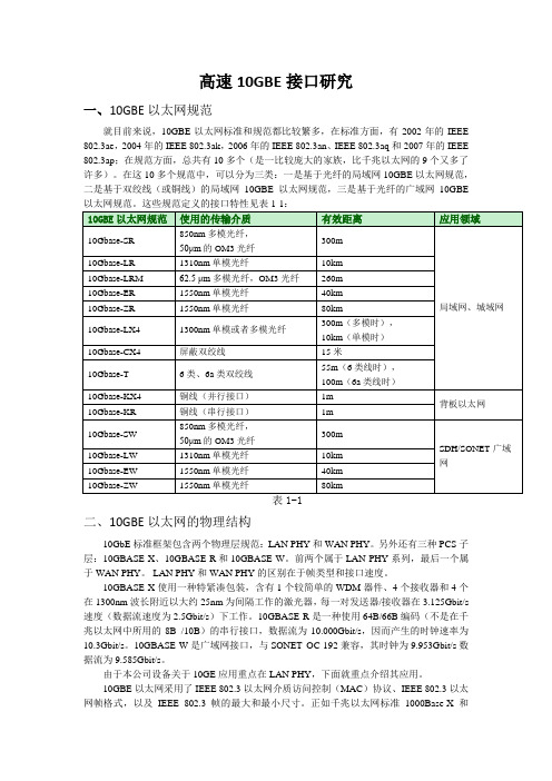
高速10GBE接口研究一、10GBE以太网规范就目前来说,10GBE以太网标准和规范都比较繁多,在标准方面,有2002年的IEEE 802.3ae,2004年的IEEE 802.3ak,2006年的IEEE 802.3an、IEEE 802.3aq和2007年的IEEE 802.3ap;在规范方面,总共有10多个(是一比较庞大的家族,比千兆以太网的9个又多了许多)。
在这10多个规范中,可以分为三类:一是基于光纤的局域网10GBE以太网规范,二是基于双绞线(或铜线)的局域网10GBE以太网规范,三是基于光纤的广域网10GBE二、10GBE以太网的物理结构10GbE标准框架包含两个物理层规范:LAN PHY和WAN PHY。
另外还有三种PCS子层:10GBASE-X、10GBASE-R和10GBASE-W。
前两个属于LAN PHY系列,最后一个属于WAN PHY。
LAN PHY和WAN PHY的区别在于帧类型和接口速度。
10GBASE-X使用一种特紧凑包装,含有1个较简单的WDM器件、4个接收器和4个在1300nm波长附近以大约25nm为间隔工作的激光器,每一对发送器/接收器在3.125Gbit/s 速度(数据流速度为2.5Gbit/s)下工作。
10GBASE-R是一种使用64B/66B编码(不是在千兆以太网中所用的8B /10B)的串行接口,数据流为10.000Gbit/s,因而产生的时钟速率为10.3Gbit/s。
10GBASE-W是广域网接口,与SONET OC-192兼容,其时钟为9.953Gbit/s数据流为9.585Gbit/s。
由于本公司设备关于10GE应用重点在LAN PHY,下面就重点介绍其应用。
10GBE以太网采用了IEEE 802.3以太网介质访问控制(MAC)协议、IEEE 802.3以太网帧格式,以及IEEE 802.3帧的最大和最小尺寸。
正如千兆以太网标准1000Base-X和1000Base-T保留了以太网模型的基本内容一样,10GBE以太网在本质上仍然是以太网在速度和距离方面的自然进化。
- 1、下载文档前请自行甄别文档内容的完整性,平台不提供额外的编辑、内容补充、找答案等附加服务。
- 2、"仅部分预览"的文档,不可在线预览部分如存在完整性等问题,可反馈申请退款(可完整预览的文档不适用该条件!)。
- 3、如文档侵犯您的权益,请联系客服反馈,我们会尽快为您处理(人工客服工作时间:9:00-18:30)。
10Gb以太网应用指南10Gb以太网应用指南毫无疑问,为了能用一种解决方案来支持存储、数据中心和LAN,网络工程师正在建立10千兆以太网网络。
但是,对于设计和管理数据中心及其连接,从基础布线到网络组件的方方面面,IT团队都有很多选择。
在本手册中,我们划分了以太网与数据中心、云计算、802.11n、交换机等几个方面,学习如何选择正确的可以影响10千兆以太网距离、速度和总体性能的布线方式。
同时,通过介绍灵活性和阻止延时来了解10千兆以太网网络如何影响数据中心优化。
了解即将使用的10千兆以太网协议如何处理数据包丢失的挑战以及如何实现网络中更有效的流量优先级划分等内容。
以太网与数据中心10 GbE已经最终进化为一个可行的解决方法——至少目前是。
了解10千兆网络是如何为在数据中心和存储处理网络负荷和阻止延时方面减少开支和增加灵活性的。
IEEE和Internet Engineering Task Force (IETF)目前正在着手开发一些能够提高网络有效性和减少数据包丢失类似情况发生的协议。
他们的工作对于确保Fibre Channel over Ethernet (FCoE)和Internet SCSI (iSCSI)的性能是至关重要的。
以10 Gigabit Ethernet优化数据中心聚合增强型以太网:新协议增强数据中心以太网以太网与云计算今年关于“云”计算的探讨相当的多。
企业开始考虑的不仅是目前他们的企业看起来是如何的,而且还在考虑以后它需要如何架构。
这样他们会开始考虑:我们是否要外包一个公用“云”,还是开始考虑如何建立一个专有的“云”?这几乎对每一个公司而言都是很重要且值得深入探讨的。
探讨Arista的“云”计算网络和10 Gigabit Ethernet(一)探讨Arista的“云”计算网络和10 Gigabit Ethernet(二)以太网与802.11n市场以及无线设备的数量和多样性正日益提升,更多的公司正部署无线电话、打印机、桌上电脑和其它的行业特定设备,如医疗设备等,这种增生正在支持Wi-Fi的设备中推动着一个快速的增长。
在公司目前的WLAN部署过快时,802.11回答了许多公司目前正奋力解决的范围和性能问题。
802.11n:以太网的终结?以太网与交换机随着10G以太网的发展和思科Nexus系列交换机产品的发布,曾经被认为已经成熟的以太网市场面临着新一轮的革新。
服务器虚拟化和前瞻应用对高速带宽的需求促使厂商去发展和应用下一代以太网技术。
10G以太网掀起网络交换革新浪潮综合技巧大量不同的网线和互连类型都能够支持10 Gigabit Ethernet (10 GbE)。
解决方案的不同在于最大互连距离、功率和发热、信号延迟时间、可靠性和对未来需求的可适应性上。
总开销不止包括设备接口和网线的花费。
人力往往也是其中的一个主要的因素。
选择一个解决方案需要针对我们的应用需求来仔细地评估每个选项。
10G以太网互连解决方案——需谨慎使用10Base—T/2/5/F/35—以太网100Base-(T) TX/T4/FX-以太网以10 Gigabit Ethernet优化数据中心Ethernet在很长时间里都是占主导地位的LAN技术。
目前,10 Gigabit Ethernet (10 GbE)的出现已经激发了数据中心新的应用。
有两个主要因素使之成为可能:竞争性的价格和性能简化数据中心网络的需求Gigabit Ethernet能够远远满足大多数的LAN应用,但是,它对于将服务器与存储区域网络(SAN)和网络附加存储器(NAS)之间的连接,或者服务器之间的连接则是不够的。
Fibre Channel和InfiniBand已经广泛用来满足这些目标了。
Fibre Channel支持最高达到8 Gbps的速率,常见的InfiniBand接口支持10 Gbps速率,并且还有20 Gbps的服务器和交换机端口。
10 GbE的价格和性能虽然10 GbE无法匹配高端InfiniBand传输速率,但是它对于大多数数据中心还是足够的。
尽管性能很有竞争力,但是10 GbE还没有被很快采用。
10 GbE标准IEEE Std 802.3ae在2002年已经完成,但是,高昂的组件价格延缓了开始的接受度。
现在价格降下来了,这样,10 GbE接口卡和交换机的销售也加速起来了。
2008年8月,加州Redwood City的一家市场调查公司Dell'Oro Group,报告了2008年第二季度10 GbE交换机端口的发货第一次超过了250,000。
原始数据速率并不是唯一重要的因素。
好的SAN性能要求服务器和存储之间有较低的延迟时间。
大多数Ethernet交换机都是设计用于LAN的。
它们必须在开始传输之前接收完整输入桢。
交换机供应商目前通过为数据中心应用而专门设计的交换机来解决这个问题。
在读取了足够确认目标地址的输入桢之后,低延迟交换机便开始向输出链路传输数据。
结果是,低延迟的交换机比InfiniBand交换机更有竞争力。
降低服务器CPU负载和冗余处理服务器CPU负载是一个关键的性能因素。
在大多数计算机系统中,CPU处理需要用来支持网络传输的数据复制和协议处理。
随着数据传输速率的增加,CPU负载也会增大。
在10 Gbps时, CPU的处理负载就无法接受了。
网卡供应商已经在他们的10 GbE卡上整合了三个机制来处理这个问题。
TCP/IP卸载引擎(TOE)是一个网卡上的有特定用途的处理器。
TOE用于将协议处理从CPU转移到网络接口上。
减少负荷可以提高CPU应用性能。
因为优化网卡处理器经过优化后可以更快地传输桢,这样就降低了延迟时间。
远程内存直接读取(Remote Direct Memory Access,RDMA)为服务器到服务器的数据传输提供一个高效的机制。
它通过直接将数据从应用内存空间拷贝到网卡上的方式来减少延迟和CPU负载。
这种单一硬件拷贝避免了先从应用内存拷贝到内核,再拷贝到网络设置驱动器,然后才拷贝到网卡的三步过程。
iWARP (Internet Wide Area RDMA Protocol)是由Internet Engineering Task Force (IETF)开发的,它可以在没有任何服务器操作系统支持的情况下,让一台服务器上的应用直接读取或写入另一台服务器上运行的应用。
使用TOE和RDMA需要修改操作系统软件。
其中必须删除协议处理代码。
Microsoft已经提供TCP Chimney Offload来支持Windows Server 2003、Vista 和Windows Server 2008上的TOE和RDMA。
OpenFabrics Alliance正在开发TOE和RDMA的Linux支持。
简化数据中心网络以Ethernet取代Fibre Channel和InfiniBand可以节省开支和添加灵活性。
Fibre Channel和InfiniBand是专门用于连接服务器和存储的技术。
它们两者都不能扩展到数据中心。
一个10 GbE网络和一个交换机就可以支持LAN、服务器到服务器通信以及SAN,同时还可以连接广域网。
数据中心职员都熟悉Ethernet和IP网络技术,因此用一个网络替代多个网络可以简化员工培训和支持的开支。
Fibre Channel和 InfiniBand两者都要求各自特有的网线类型。
10 GbE使用标准双绞线或者光纤。
作为未来的回报,一个高容量的交换机所消耗的能量和产生的热量比两台较小的交换机要少些。
Ethernet Virtual LANs (VLANs)可以在流量模式发生变化时实现快速地迁移。
在流量级允许的条件下,LAN、服务器到服务器和SAN流量可以在相同的布线下分配到独立VLAN上,或者随着流量的增加迁移到单独的线路上。
Ethernet和 iSCSI上的Fibre ChannelEthernet(FCoE)上的Fibre Channel是由一群设备供应商一起开发的,它是在保持用户在部署Fibre Channel的投资的同时利用单一网络技术的一种方式。
Fibre Channel 数据包不再使用Fibre Channel接口、网线和交换机传输,而是通过Ethernet传输的。
类似的,iSCSI也提供了一种保持现有系统的投资同时利用单一网络的好处。
通过iSCSI连接的存储对于服务器而言就像是一个直接连接的SCSI磁盘驱动器。
标准的SCSI命令是在Ethernet 上的通过TCP/IP协议传输的。
Fibre Channel和InfiniBand技术,与Ethernet相反,它们可以保证在传输中不会丢失数据包。
为了纠正这个问题,目前IEEE仍正在开发一个Ethernet协议,它将通过提供灵活的优先级划分和消除网络拥挤来减少数据包丢失。
鉴于未来价格的降低、性能的提高、电源的节省和需求简化,这个产品将继续提高10 GbE在数据中心的使用率。
聚合增强型以太网:新协议增强数据中心以太网价格、性能和灵活性已经让10 Gigabit Ethernet (10 GbE)成为数据中心的一个有吸引力的选择方案。
虽然10GbE 也已经有所进展,但是,在现有以太网协议中功能的缺失限制了其更好地突破。
以太网存在的主要问题是,当交换机或者终端节点被输入的数据包暂时淹没时,它无法保证数据包不会丢失。
IEEE和Internet Engineering Task Force (IETF)目前正在着手开发协议以便提高网络有效性和减少数据包丢失等类似情况发生。
他们所从事的工作对于保证Fibre Channel over Ethernet (FCoE)和Internet SCSI (iSCSI)的性能是至关重要的。
目前正在解决的问题:•流量优先级划分•拥塞控制•改良路由选择这些用来处理这些问题的协议集已经被命名为整合增强型以太网(Converged Enhanced Ethernet)或者无损以太网(Lossless Ethernet)。
流量优先级划分和控制相对于其它竞争技术,10 GbE的主要优势在于存储区域网络(SAN)的独立网络、服务器到服务器通信以及用单一10 GbE 网络替代LAN。
10 GbE链路可能有足够的带宽来传输所有的三种数据类型,然而,暴增的流量可能冲垮交换机或者终端。
SAN性能对于延时相当的敏感。
存储的访问减慢对于服务器和应用性能有一定的影响。
服务器到服务器流量也受到延时的影响,而LAN流量则较为不敏感。
因此,必须有一个机制来对重要流量分配高优先级,而低优先级数据则直有在链路可用时才传输。
现有以太网协议并不提供所需要的控制。
接受节点可以发送一个802.3x PAUSE命令中止数据流,但是PAUSE会终止所有数据包。