TI MOTOR DRIVER
DRV8801

DRV8800-Q1DRV8801-Q1 SLVSAS7–FEBRUARY2011DMOS FULL-BRIDGE MOTOR DRIVERSCheck for Samples:DRV8800-Q1,DRV8801-Q1FEATURES•Low-Power Mode•Qualified for Automotive Applications•Synchronous Rectification•Low ON-Resistance[R ds(ON)]Outputs•Diagnostic Output•Overcurrent Protection•Internal Undervoltage Lockout(UVLO)•Motor Lead Short-to-Supply Protection•Crossover-Current Protection•Short-to-Ground Protection•16-Pin QFN With PowerPAD™PackageDESCRIPTION/ORDERING INFORMATIONDesigned to control dc motors by using pulse width modulation(PWM),the DRV8800-Q1/DRV8801-Q1is capable of peak output currents up to±2.8A and operating voltages up to36V.The PHASE and ENABLE inputs provide dc motor speed and direction control by applying external pulse-width modulation(PWM)and control signals.Internal synchronous rectification control circuitry provides lower power dissipation during PWM operation.Internal circuit protection includes motor lead short-to-supply/short-to-ground,thermal shutdown with hysteresis, undervoltage monitoring of VBB and VCP,and crossover-current protection.The DRV8800-Q1/DRV8801-Q1is supplied in a thin-profile16-pin QFN(RTY)PowerPAD™package,providing enhanced thermal dissipation.The devices are lead free(Pb free).ORDERING INFORMATIONT A PACKAGE(1)(2)ORDERABLE PART NUMBER TOP-SIDE MARKINGDRV8800QRTYRQ1PREVIEWPlastic QFN16(S-PQFP-16)–RTYDRV8801QRTYRQ1DRV8801Q–40°C to125°CDRV8800QPWPRQ1PREVIEWTSSOP-PWPDRV8801QPWPRQ1PREVIEW(1)For the most current package and ordering information,see the Package Option Addendum at the end of this document,or see the TIwebsite at .(2)Package drawings,thermal data,and symbolization are available at /packaging.Please be aware that an important notice concerning availability,standard warranty,and use in critical applications of TexasInstruments semiconductor products and disclaimers thereto appears at the end of this data sheet.PowerPAD is a trademark of Texas Instruments Incorporated.UNLESS OTHERWISE NOTED this document contains©2011,Texas Instruments Incorporated PRODUCTION DATA information current as of publication date.Products conform to specifications per the terms of TexasInstruments standard warranty.Production processing does notnecessarily include testing of all parameters.DRV8800-Q1RTY PACKAGE (TOP VIEW)DRV8801-Q1RTY PACKAGE (TOP VIEW)PHASE GND nSLEEP ENABLEPHASE GND nSLEEP ENABLEGND CP2CP1OUT BGND CP2CP1OUTBNC –Do not connectN CO U T AS E N S EV B BM O D E 2O U T A S E N S EV B BM O D En F A U L TV R E GV C PM O D E 1n F A U L TV P R O P IV C PDRV8800-Q1DRV8801-Q1SLVSAS7–FEBRUARY 2011TERMINAL FUNCTIONSTERMINALNAMEDESCRIPTIONNO.DRV8800-Q1DRV8801-Q11PHASE PHASE Phase logic input for direction control 2GND GND Ground3nSLEEP nSLEEP Sleep logic input 4ENABLE ENABLE Enable logic input5NC MODE 2No connect (DRV8800-Q1),Mode 2logic input (DRV8801-Q1)6OUT+OUT+DMOS full-bridge output positive 7SENSE SENSE Sense power return 8VBB VBB Load supply voltage9OUT-OUT-DMOS full-bridge output negative 10CP1CP1Charge-pump capacitor 111CP2CP2Charge-pump capacitor 212GND GND Ground13VCP VCP Reservoir capacitor14VREG VPROPI Regulated voltage (DRV8800-Q1),Winding current proportional voltage output (DRV8801-Q1)15nFAULT nFAULT Fault open-drain output 16MODE MODE 1Mode logic inputPowerPADPowerPADExposed pad for thermal dissipation connect to GND pins2Submit Documentation Feedback©2011,Texas Instruments IncorporatedProduct Folder Link(s):DRV8800-Q1DRV8801-Q112345678910111213141516PWP PACKAGE (TOP VIEW)NC VREG VCP GND CP2CP1OUT -VBBnFAULT MODE PHASE GND nSLEEP ENABLE OUT+SENSEDRV8800-Q112345678910111213141516PWP PACKAGE (TOP VIEW)MODE 2VPROPI VCP GND CP2CP1OUT -VBBnFAULT MODE 1PHASE GND nSLEEP ENABLE OUT+SENSEDRV8801-Q1DRV8800-Q1DRV8801-Q1SLVSAS7–FEBRUARY 2011TERMINAL FUNCTIONSTERMINALNAMEDESCRIPTIONNO.DRV8800-Q1DRV8801-Q11nFAULT nFAULT Fault open-drain output 2MODE MODE 1Mode logic input3PHASE PHASE Logic input for direction control 4GND GND Ground5nSLEEP nSLEEP Sleep logic input 6ENABLE ENABLE Enable logic input7OUT+OUT+DMOS full-bridge output positive 8SENSE SENSE Sense power return 9VBB VBB Load supply voltage10OUT-OUT-DMOS full-bridge output negative 11CP1CP1Charge-pump capacitor 112CP2CP2Charge-pump capacitor 213GND GND Ground14VCP VCP Reservoir capacitor15VREG VPROPI Regulated voltage (DRV8800-Q1),Winding current proportional voltage output (DRV8801-Q1)16NC MODE 2No connect (DRV8800-Q1),Mode 2logic input (DRV8801-Q1)PowerPADPowerPADExposed pad for thermal dissipation connect to GND pins©2011,Texas Instruments Incorporated Submit Documentation Feedback3Product Folder Link(s):DRV8800-Q1DRV8801-Q1DRV8800-Q1DRV8801-Q1SLVSAS7–FEBRUARY 2011DRV8800-Q1TYPICAL APPLICATION DIAGRAM4Submit Documentation Feedback©2011,Texas Instruments IncorporatedProduct Folder Link(s):DRV8800-Q1DRV8801-Q1DRV8800-Q1DRV8801-Q1 SLVSAS7–FEBRUARY2011DRV8801-Q1TYPICAL APPLICATION DIAGRAM©2011,Texas Instruments Incorporated Submit Documentation Feedback5Product Folder Link(s):DRV8800-Q1DRV8801-Q1.1ufDRV8800-Q1DRV8801-Q1SLVSAS7–FEBRUARY 2011DRV8800-Q1FUNCTIONAL BLOCK DIAGRAM6Submit Documentation Feedback©2011,Texas Instruments IncorporatedProduct Folder Link(s):DRV8800-Q1DRV8801-Q1.1uf DRV8800-Q1 DRV8801-Q1 SLVSAS7–FEBRUARY2011DRV8801-Q1FUNCTIONAL BLOCK DIAGRAM©2011,Texas Instruments Incorporated Submit Documentation Feedback7Product Folder Link(s):DRV8800-Q1DRV8801-Q1DRV8800-Q1DRV8801-Q1SLVSAS7– ABSOLUTE MAXIMUM RATINGS(1)over operating free-air temperature range(unless otherwise noted)MIN MAX UNIT VBB Load supply voltage(2)40V Output current 2.8AV Sense Sense voltage±500mV VBB to OUTx36VOUTx to SENSE36V VDD Logic input voltage(2)–0.37V Human-Body Model(HBM)±2kV ESD rating Machine Model(MM)150V Charged-Device Model(CDM)750Continuous total power dissipation See Dissipation Ratings TableT A Operating free-air temperature range–40125°CT J Maximum junction temperature190°CT stg Storage temperature range–40125°C (1)Stresses beyond those listed under“absolute maximum ratings”may cause permanent damage to the device.These are stress ratingsonly,and functional operation of the device at these or any other conditions beyond those indicated under“recommended operating conditions”is not implied.Exposure to absolute-maximum-rated conditions for extended periods may affect device reliability.(2)All voltage values are with respect to network ground terminal.DISSIPATION RATINGST A=25°C DERATING FACTOR PACKAGEθJAPOWER RATING ABOVE T A=25°C RTY41.63W24mW/CPWP32.6 3.8W31mW/C RECOMMENDED OPERATING CONDITIONSMIN NOM MAX UNITV IN Input voltage,VBB83238VT A Operating free-air temperature–40125°C8Submit Documentation Feedback©2011,Texas Instruments IncorporatedProduct Folder Link(s):DRV8800-Q1DRV8801-Q1DRV8800-Q1DRV8801-Q1 SLVSAS7–FEBRUARY2011 ELECTRICAL CHARACTERISTICSover recommended operating conditions(unless otherwise noted)PARAMETER TEST CONDITIONS MIN TYP MAX UNITf PWM<50kHz6mA IBB Motor supply current Charge pump on,Outputs disabled 3.2Sleep mode10μAV IH2PHASE,ENABLE,V MODE input voltageV IL0.8V IH 2.7nSLEEP input voltage VV IL0.8I IH V IN=2V<1.020PHASE,MODE input currentμAI IL V IN=0.8V–20≤–2.020I IH V IN=2V40100ENABLE input currentμAI IL V IN=0.8V1640I IH V IN=2.7V2750nSLEEP input currentμAI IL V IN=0.8V<110V OL nFAULT output voltage I sink=1mA0.4V VBBNFR VBB nFAULT release8V<VBB<40V1213.8VV IHys Input hysteresis,except nSLEEP100500800mVSource driver,I OUT=–2.8A,T J=25°C0.48Source driver,I OUT=–2.8A,T J=125°C0.740.85R ds(ON)Output ON resistanceΩSink driver,I OUT=2.8A,T J=25°C0.35Sink driver,I OUT=2.8A,T J=125°C0.520.7SENSE connected to ground through someVTRP RSENSE/ISense voltage trip500mVresistanceSource diode,I f=–2.8A 1.4V f Body diode forward voltage VSink diode,I f=2.8A 1.4PWM,Change to source or sink ON600t pd Propagation delay time nsPWM,Change to source or sink OFF100t COD Crossover delay500ns DAGain Differential AMP gain Sense=0.1V to0.4V5V/V Protection CircuitryVUV UVLO threshold VBB increasing 6.57.5V IOCP Overcurrent threshold3At OCP Overcurrent protection period 1.2ms TJW Thermal warning temperature Temperature increasing160°C TJWHys Thermal warning hysteresis Recovery=TJW–TJWHys15°C TJTSD Thermal shutdown temperature Temperature increasing175°C TJTSDHys Thermal shutdown hysteresis Recovery=TJTSD–TJTSDHys15°C©2011,Texas Instruments Incorporated Submit Documentation Feedback9Product Folder Link(s):DRV8800-Q1DRV8801-Q1SLEEP ENABLE PHASE MODEV BBV BBV OUT-V OUT+I OUTX(~200us)DRV8800-Q1DRV8801-Q1SLVSAS7–FEBRUARY 2011Figure 1.PWM Control Timing10Submit Documentation Feedback©2011,Texas Instruments IncorporatedProduct Folder Link(s):DRV8800-Q1DRV8801-Q1I PEAKI I OUTx V OUT +V OUT-Enable,Sourceor SinkBLANKCharge PumpCounter NFAULT Motor LeadShort Condition Normal DC Motor CapacitanceDRV8800-Q1DRV8801-Q1 SLVSAS7–FEBRUARY 2011Figure 2.Overcurrent Control TimingFUNCTIONAL DESCRIPTIONDevice OperationThe DRV8800-Q1/DRV8801-Q1is designed to drive one dc motor.The current through the output full-bridgeswitches and all N-channel DMOS are regulated with a fixed off-time PWM control circuit.Logic InputsIt is recommended to use a high-value pullup resistor when logic inputs are pulled up to V DD .This resistor limitsthe current to the input in case an overvoltage event occurs.Logic inputs are nSLEEP,MODE,PHASE,andENABLE.Voltages higher than 7V on any logic input can cause damage to the input structure.VREG (DRV8800-Q1Only)This output represents a measurement of the internal regulator voltage.This pin should be left disconnected.Avoltage of approximately 7.5V can be measured at this pin.VPROPI (DRV8801-Q1Only)This output offers an analog voltage proportional to the winding current.Voltage at this terminal is five timesgreater than the motor winding current (VPROPI =5×I).VPROPI is meaningful only if there is a resistorconnected to the SENSE pin.If SENSE is connected to ground,VPROPI measures 0V.During slow decay,VPROPI outputs 0V.VPROPI can output a maximum of 2.5V,since at 500mV on SENSE,the H-bridge isdisabled.DRV8800-Q1DRV8801-Q1SLVSAS7– Charge PumpThe charge pump is used to generate a supply above VBB to drive the source-side DMOS gates.A0.1-μF ceramic monolithic capacitor should be connected between CP1and CP2for pumping purposes.A0.1-μF ceramic monolithic capacitor,CStorage,should be connected between VCP and VBB to act as a reservoir to run the high-side DMOS devices.The VCP voltage level is internally monitored and,in the case of a fault condition, the outputs of the device are disabled.ShutdownAs a measure to protect the device,faults caused by very high junction temperatures or low voltage on VCP disable the outputs of the device until the fault condition is removed.At power on,the UVLO circuit disables the drivers.Low-Power ModeControl input nSLEEP is used to minimize power consumption when the DRV8800-Q1/DRV8801-Q1is not in use.This disables much of the internal circuitry,including the internal voltage rails and charge pump.nSLEEP is asserted low.A logic high on this input pin results in normal operation.When switching from low to high,the user should allow a1-ms delay before applying PWM signals.This time is needed for the charge pump to stabilize.•MODE1(MODE on the DRV8800-Q1)Input MODE1is used to toggle between fast-decay mode and slow-decay mode.A logic high puts the device in slow-decay mode.•MODE2(DRV8801-Q1only)MODE2is used to select which set of drivers(high side versus low side)is used during the slow-decay recirculation.MODE2is meaningful only when MODE1is asserted high.A logic high on MODE2has current recirculation through the high-side drivers.A logic low has current recirculation through the low-side drivers.BrakingThe braking function is implemented by driving the device in slow-decay mode(MODE1pin is high)and deasserting the enable to low.Because it is possible to drive current in both directions through the DMOS switches,this configuration effectively shorts out the motor-generated BEMF as long as the ENABLE chop mode is asserted.The maximum current can be approximated by VBEMF/RL.Care should be taken to ensure that the maximum ratings of the device are not exceeded in worse-case braking situations–high-speed and high-inertia loads.Diagnostic OutputThe nFAULT pin signals a problem with the chip via an open-drain output.A motor fault,undervoltage condition, or T J>160°C drives the pin active low.This output is not valid when nSLEEP puts the device into minimum power dissipation mode(i.e.,nSLEEP is low).nFAULT stays asserted(nFAULT=L)until VBB reaches VBBNFR to give the charge pump headroom to reach its undervoltage threshold.nFAULT is a status-only signal and does not affect any device functionality.The H-bridge portion still operates normally down to VBB=8V with nFAULT asserted.Thermal Shutdown(TSD)Two die-temperature monitors are integrated on the chip.As die temperature increases toward the maximum,a thermal warning signal is triggered at160°C.This fault drives the nFAULT low,but does not disable the operation of the chip.If the die temperature increases further,to approximately175°C,the full-bridge outputs are disabled until the internal temperature falls below a hysteresis of15°C.DRV8800-Q1DRV8801-Q1 SLVSAS7–FEBRUARY2011Control Logic Table(1)PINSOPERATION PHASE ENABLE MODE1MODE2nSLEEP OUT+OUT-11X X1H L Forward01X X1L H ReverseX0101L L Brake(slow decay)Fast-decay synchronous 10011L Hrectification(2)Fast-decay synchronous 000X1H Lrectification(2)X X X X0Z Z Sleep mode(1)X=Don’t care,Z=high impedance(2)To prevent reversal of current during fast-decay synchronous rectification,outputs go to the high-impedance state as the currentapproaches0A.Overcurrent ProtectionThe current flowing through the high-side and low-side drivers is monitored to ensure that the motor lead is not shorted to supply or ground.If a short is detected,the full-bridge outputs are turned off,flag nFAULT is driven low,and a1.2-ms fault timer is started.After this1.2-ms period,t OCP,the device is then allowed to follow the input commands and another turnon is attempted(nFAULT becomes high again during this attempt).If there is still a fault condition,the cycle repeats.If after t OCP expires it is determined the short condition is not present, normal operation resumes and nFAULT is deasserted.P D =I(R2DS(on)Source+RDS(onSink))(brake)(reverse)DRV8800-Q1DRV8801-Q1SLVSAS7–APPLICATION INFORMATIONPower DissipationFirst-order approximation of power dissipation in the DRV8800-Q1/DRV8801-Q1can be calculated by examining the power dissipation in the full-bridge during each of the operation modes.DRV8800-Q1/DRV8801-Q1utilize synchronous rectification.During the decay cycle,the body diode is shorted by the low-R ds(ON)driver,which in turn reduces power dissipation in the full-bridge.In order to prevent shoot through(high-side and low-side drivers on the same side are ON at the same time),DRV8800-Q1/DRV8801-Q1implement a500-ns typical crossover delay time.During this period,the body diode in the decay current path conducts the current until the DMOS driver turns on.High current and high ambient temperature applications should take this into consideration.In addition,motor parameters and switching losses can add power dissipation that could affect critical applications.Drive CurrentThis current path is through the high-side sourcing DMOS driver,motor winding,and low-side sinking DMOS driver.Power dissipation I2R loses in one source and one sink DMOS driver,as shown in Equation1.(1)DRV8800-Q1Slow decay with synchronous rectification(brake)Low Side Fast decay with synchronous rectification(reverse)Slow decay with synchronous rectification(brake)High Side DRV8800-Q1 DRV8801-Q1 SLVSAS7–FEBRUARY2011DRV8801-Q1Figure3.Current PathFast Decay With Synchronous RectificationThis decay mode is equivalent to a phase change where the opposite drivers are switched on.When in fast decay,the motor current is not allowed to go negative(direction change).Instead,as the current approaches zero,the drivers turn off.The power calculation is the same as the drive current calculation(see Equation1).P = I (2R )D DS(on)Sink 2´DRV8800-Q1DRV8801-Q1SLVSAS7–FEBRUARY Slow-Decay SR (Brake Mode)In slow-decay mode,both low-side sinking drivers turn on,allowing the current to circulate through the H-bridge ’slow side (two sink drivers)and the load.Power dissipation I2R loses in the two sink DMOS drivers:(2)SENSEA low-value resistor can be placed between the SENSE pin and ground for current-sensing purposes.Tominimize ground-trace IR drops in sensing the output current level,the current-sensing resistor should have anindependent ground return to the star ground point.This trace should be as short as possible.For low-valuesense resistors,the IR drops in the PCB can be significant,and should be taken into account.NOTEWhen selecting a value for the sense resistor,SENSE does not exceed the maximumvoltage of ±500mV.The H-bridge is disabled and enters recirculation while motor windingcurrent is above a SENSE voltage equal or greater than 500mV.GroundA ground power plane should be located as close to the DRV8800-Q1/DRV8801-Q1as possible.The copperground plane directly under the PowerPAD package makes a good location.This pad can then be connected toground for this purpose.LayoutThe printed circuit board (PCB)should use a heavy ground plane.For optimum electrical and thermalperformance,the DRV8800-Q1/DRV8801-Q1must be soldered directly onto the board.On the underside of theDRV8800-Q1/DRV8801-Q1is a PowerPAD package,which provides a path for enhanced thermal dissipation.The thermal pad should be soldered directly to an exposed surface on the PCB.Thermal vias are used totransfer heat to other layers of the PCB.For more information on this technique,please refer to documentSLMA002.The load supply pin,VBB,should be decoupled with an electrolytic capacitor (typically 100μF)in parallel with aceramic capacitor placed as close as possible to the device.The ceramic capacitors between VCP and VBB,connected to VREG,and between CP1and CP2should be as close to the pins of the device as possible,inorder to minimize lead inductance.PACKAGE OPTION ADDENDUM 7-Mar-2011Addendum-Page 1PACKAGING INFORMATION Orderable DeviceStatus (1)Package Type Package Drawing Pins Package Qty Eco Plan (2)Lead/Ball Finish MSL Peak Temp (3)Samples (Requires Login)DRV8801QRTYRQ1ACTIVE QFN RTY 163000Green (RoHS & no Sb/Br)CU NIPDAU Level-3-260C-168 HR (1) The marketing status values are defined as follows:ACTIVE: Product device recommended for new designs.LIFEBUY: TI has announced that the device will be discontinued, and a lifetime-buy period is in effect.NRND: Not recommended for new designs. Device is in production to support existing customers, but TI does not recommend using this part in a new design.PREVIEW: Device has been announced but is not in production. Samples may or may not be available.OBSOLETE: TI has discontinued the production of the device.(2) Eco Plan - The planned eco-friendly classification: Pb-Free (RoHS), Pb-Free (RoHS Exempt), or Green (RoHS & no Sb/Br) - please check /productcontent for the latest availability information and additional product content details.TBD: The Pb-Free/Green conversion plan has not been defined.Pb-Free (RoHS): TI's terms "Lead-Free" or "Pb-Free" mean semiconductor products that are compatible with the current RoHS requirements for all 6 substances, including the requirement that lead not exceed 0.1% by weight in homogeneous materials. Where designed to be soldered at high temperatures, TI Pb-Free products are suitable for use in specified lead-free processes.Pb-Free (RoHS Exempt): This component has a RoHS exemption for either 1) lead-based flip-chip solder bumps used between the die and package, or 2) lead-based die adhesive used between the die and leadframe. The component is otherwise considered Pb-Free (RoHS compatible) as defined above.Green (RoHS & no Sb/Br): TI defines "Green" to mean Pb-Free (RoHS compatible), and free of Bromine (Br) and Antimony (Sb) based flame retardants (Br or Sb do not exceed 0.1% by weight in homogeneous material)(3) MSL, Peak Temp. -- The Moisture Sensitivity Level rating according to the JEDEC industry standard classifications, and peak solder temperature.Important Information and Disclaimer:The information provided on this page represents TI's knowledge and belief as of the date that it is provided. TI bases its knowledge and belief on information provided by third parties, and makes no representation or warranty as to the accuracy of such information. Efforts are underway to better integrate information from third parties. TI has taken and continues to take reasonable steps to provide representative and accurate information but may not have conducted destructive testing or chemical analysis on incoming materials and chemicals.TI and TI suppliers consider certain information to be proprietary, and thus CAS numbers and other limited information may not be available for release.In no event shall TI's liability arising out of such information exceed the total purchase price of the TI part(s) at issue in this document sold by TI to Customer on an annual basis.OTHER QUALIFIED VERSIONS OF DRV8801-Q1 :•Catalog: DRV8801NOTE: Qualified Version Definitions:•Catalog - TI's standard catalog productTAPE AND REEL INFORMATION*All dimensions are nominal Device Package Type Package DrawingPinsSPQ Reel Diameter (mm)Reel Width W1(mm)A0(mm)B0(mm)K0(mm)P1(mm)W (mm)Pin1Quadrant DRV8801QRTYRQ1QFN RTY 163000330.012.4 4.25 4.25 1.158.012.0Q2*All dimensions are nominalDevice Package Type Package Drawing Pins SPQ Length(mm)Width(mm)Height(mm)DRV8801QRTYRQ1QFN RTY163000367.0367.035.0IMPORTANT NOTICETexas Instruments Incorporated and its subsidiaries(TI)reserve the right to make corrections,enhancements,improvements and other changes to its semiconductor products and services per JESD46C and to discontinue any product or service per JESD48B.Buyers should obtain the latest relevant information before placing orders and should verify that such information is current and complete.All semiconductor products(also referred to herein as“components”)are sold subject to TI’s terms and conditions of sale supplied at the time of order acknowledgment.TI warrants performance of its components to the specifications applicable at the time of sale,in accordance with the warranty in TI’s terms and conditions of sale of semiconductor products.Testing and other quality control techniques are used to the extent TI deems necessary to support this warranty.Except where mandated by applicable law,testing of all parameters of each component is not necessarily performed.TI assumes no liability for applications assistance or the design of Buyers’products.Buyers are responsible for their products and applications using TI components.To minimize the risks associated with Buyers’products and applications,Buyers should provide adequate design and operating safeguards.TI does not warrant or represent that any license,either express or implied,is granted under any patent right,copyright,mask work right,or other intellectual property right relating to any combination,machine,or process in which TI components or services are rmation published by TI regarding third-party products or services does not constitute a license to use such products or services or a warranty or endorsement e of such information may require a license from a third party under the patents or other intellectual property of the third party,or a license from TI under the patents or other intellectual property of TI.Reproduction of significant portions of TI information in TI data books or data sheets is permissible only if reproduction is without alteration and is accompanied by all associated warranties,conditions,limitations,and notices.TI is not responsible or liable for such altered rmation of third parties may be subject to additional restrictions.Resale of TI components or services with statements different from or beyond the parameters stated by TI for that component or service voids all express and any implied warranties for the associated TI component or service and is an unfair and deceptive business practice. TI is not responsible or liable for any such statements.Buyer acknowledges and agrees that it is solely responsible for compliance with all legal,regulatory and safety-related requirements concerning its products,and any use of TI components in its applications,notwithstanding any applications-related information or support that may be provided by TI.Buyer represents and agrees that it has all the necessary expertise to create and implement safeguards which anticipate dangerous consequences of failures,monitor failures and their consequences,lessen the likelihood of failures that might cause harm and take appropriate remedial actions.Buyer will fully indemnify TI and its representatives against any damages arising out of the use of any TI components in safety-critical applications.In some cases,TI components may be promoted specifically to facilitate safety-related applications.With such components,TI’s goal is to help enable customers to design and create their own end-product solutions that meet applicable functional safety standards and requirements.Nonetheless,such components are subject to these terms.No TI components are authorized for use in FDA Class III(or similar life-critical medical equipment)unless authorized officers of the parties have executed a special agreement specifically governing such use.Only those TI components which TI has specifically designated as military grade or“enhanced plastic”are designed and intended for use in military/aerospace applications or environments.Buyer acknowledges and agrees that any military or aerospace use of TI components which have not been so designated is solely at the Buyer's risk,and that Buyer is solely responsible for compliance with all legal and regulatory requirements in connection with such use.TI has specifically designated certain components which meet ISO/TS16949requirements,mainly for automotive ponents which have not been so designated are neither designed nor intended for automotive use;and TI will not be responsible for any failure of such components to meet such requirements.Products ApplicationsAudio /audio Automotive and Transportation /automotiveAmplifiers Communications and Telecom /communicationsData Converters Computers and Peripherals /computersDLP®Products Consumer Electronics /consumer-appsDSP Energy and Lighting /energyClocks and Timers /clocks Industrial /industrialInterface Medical /medicalLogic Security /securityPower Mgmt Space,Avionics and Defense /space-avionics-defense Microcontrollers Video and Imaging /videoRFID OMAP Mobile Processors /omap TI E2E Community Wireless Connectivity /wirelessconnectivityMailing Address:Texas Instruments,Post Office Box655303,Dallas,Texas75265Copyright©2012,Texas Instruments Incorporated。
DRV8829PWPR;DRV8829PWP;DRV8829EVM;中文规格书,Datasheet资料

DRV8829 SLVSA74B–MAY2010–REVISED MAY2011H-BRIDGE MOTOR DRIVER ICCheck for Samples:DRV8829FEATURES APPLICATIONS•Single H-Bridge Current-Control Motor Driver•Automatic Teller Machines –Capable of Driving One Winding of a•Money Handling MachinesBipolar Stepper or One DC Motor•Video Security Cameras –Five-Bit Winding Current Control Allows Up•Printersto32Current Levels•Scanners–Low MOSFET On-Resistance•Office Automation Machines•5-A Maximum Drive Current at24V,25°C•Gaming Machines•Built-In3.3-V Reference Output•Factory Automation•Industry-Standard Parallel Digital Control•RoboticsInterface•8.2-V to45-V Operating Supply Voltage Range•Thermally Enhanced Surface Mount PackageDESCRIPTIONThe DRV8829provides an integrated motor driver solution for DC and stepper motors used in cash handling machines and other automated equipment applications.The device has one H-bridge driver,and can drive one winding of a bipolar stepper motor or one DC motor.The output driver block consists of N-channel power MOSFET’s configured as a single full H-bridge to drive the motor winding.The DRV8829can supply up to5-A peak or3.5-A RMS output current(with proper heatsinking at24V and25°C).A simple parallel digital control interface is compatible with industry-standard devices.Decay mode is programmable.Internal shutdown functions are provided for overcurrent protection,short circuit protection,undervoltage lockout and overtemperature.The DRV8829is available in a28-pin HTSSOP package with PowerPAD™(Eco-friendly:RoHS&no Sb/Br).ORDERING INFORMATION(1)ORDERABLE PART TOP-SIDE T A PACKAGE(2)NUMBER MARKING –40°C to85°C PowerPAD™(HTSSOP)-PWP Reel of2000DRV8829PWPR8829(1)For the most current packaging and ordering information,see the Package Option Addendum at the end of this document,or see the TIweb site at .(2)Package drawings,thermal data,and symbolization are available at /packaging.Please be aware that an important notice concerning availability,standard warranty,and use in critical applications of TexasInstruments semiconductor products and disclaimers thereto appears at the end of this data sheet.PowerPAD is a trademark of Texas Instruments.DRV8829SLVSA74B–MAY2010–REVISED DEVICE INFORMATIONFunctional Block DiagramPWP (HTSSOP) PACKAGE DRV8829 SLVSA74B–MAY2010–REVISED MAY2011Table1.TERMINAL FUNCTIONSEXTERNAL COMPONENTS NAME PIN I/O(1)DESCRIPTIONOR CONNECTIONSPOWER AND GROUNDGND14,28-Device groundConnect to motor supply(8.2-45V).Both pins VM4,11-Bridge power supplymust be connected to same supply.Bypass to GND with a0.47-μF6.3-V ceramicV3P3OUT15O 3.3-V regulator outputcapacitor.Can be used to supply VREF.CP11IO Charge pump flying capacitor Connect a0.01-μF50-V capacitor between CP1and CP2.CP22IO Charge pump flying capacitorVCP3IO High-side gate drive voltage Connect a0.1-μF16-V ceramic capacitor to VM. CONTROLENBL21I Bridge enable Logic high to enable H-bridge.Internal pulldown.Logic high sets OUT1high,OUT2low.Internal PHASE20I Bridge phase(direction)pulldown.I023II124ISets winding current as a percentage of full-scale. I225I Current set inputsInternal pulldown.I326II427ILow=slow decay,open=mixed decay,DECAY19I Decay mode high=fast decayInternal pulldown and pullup.Active-low reset input initializes internal logic and nRESET16I Reset inputdisables the H-bridge outputs.Internal pulldown.Logic high to enable device,logic low to enter nSLEEP17I Sleep mode inputlow-power sleep mode.Internal pulldown.Reference voltage for winding current set.Both VREF12,13I Current set reference inputpins must be connected together on the PCB. STATUSLogic low when in fault condition(overtemp, nFAULT18OD Faultovercurrent)OUTPUTConnect to current sense resistor.Both pins must ISEN6,9IO Bridge ground/Isensebe connected together on the PCB.OUT15,10O Bridge output1Connect to motor winding.Both pins must beconnected together on the PCB.OUT27,8O Bridge output2(1)Directions:I=input,O=output,OZ=tri-state output,OD=open-drain output,IO=input/outputDRV8829SLVSA74B–MAY2010–REVISED ABSOLUTE MAXIMUM RATINGSover operating free-air temperature range(unless otherwise noted)(1)(2)VALUE UNITVM Power supply voltage range–0.3to47V Digital pin voltage range–0.5to7V VREF Input voltage–0.3to4V ISENSE pin voltage–0.3to0.8VPeak motor drive output current,t<1μS Internally limited AContinuous motor drive output current(3)5AContinuous total power dissipation See Dissipation Ratings tableT J Operating virtual junction temperature range–40to150°CT A Operating ambient temperature range–40to85°CT stg Storage temperature range–60to150°C (1)Stresses beyond those listed under absolute maximum ratings may cause permanent damage to the device.These are stress ratingsonly,and functional operation of the device at these or any other conditions beyond those indicated under recommended operating conditions is not implied.Exposure to absolute–maximum–rated conditions for extended periods may affect device reliability.(2)All voltage values are with respect to network ground terminal.(3)Power dissipation and thermal limits must be observed.THERMAL INFORMATIONDRV8829THERMAL METRIC(1)PWP UNITS28PINSθJA Junction-to-ambient thermal resistance(2)31.6θJCtop Junction-to-case(top)thermal resistance(3)15.9θJB Junction-to-board thermal resistance(4) 5.6°C/WψJT Junction-to-top characterization parameter(5)0.2ψJB Junction-to-board characterization parameter(6) 5.5θJCbot Junction-to-case(bottom)thermal resistance(7) 1.4(1)For more information about traditional and new thermal metrics,see the IC Package Thermal Metrics application report,SPRA953.(2)The junction-to-ambient thermal resistance under natural convection is obtained in a simulation on a JEDEC-standard,high-K board,asspecified in JESD51-7,in an environment described in JESD51-2a.(3)The junction-to-case(top)thermal resistance is obtained by simulating a cold plate test on the package top.No specificJEDEC-standard test exists,but a close description can be found in the ANSI SEMI standard G30-88.(4)The junction-to-board thermal resistance is obtained by simulating in an environment with a ring cold plate fixture to control the PCBtemperature,as described in JESD51-8.(5)The junction-to-top characterization parameter,ψJT,estimates the junction temperature of a device in a real system and is extractedfrom the simulation data for obtainingθJA,using a procedure described in JESD51-2a(sections6and7).(6)The junction-to-board characterization parameter,ψJB,estimates the junction temperature of a device in a real system and is extractedfrom the simulation data for obtainingθJA,using a procedure described in JESD51-2a(sections6and7).(7)The junction-to-case(bottom)thermal resistance is obtained by simulating a cold plate test on the exposed(power)pad.No specificJEDEC standard test exists,but a close description can be found in the ANSI SEMI standard G30-88.RECOMMENDED OPERATING CONDITIONSover operating free-air temperature range(unless otherwise noted)MIN NOM MAX UNITV M Motor power supply voltage range(1)8.245VV REF VREF input voltage(2)1 3.5VI V3P3V3P3OUT load current01mAf PWM Externally applied PWM frequency0100kHz(1)All V M pins must be connected to the same supply voltage.(2)Operational at VREF between0V and1V,but accuracy is degraded.DRV8829 SLVSA74B–MAY2010–REVISED MAY2011ELECTRICAL CHARACTERISTICSover operating free-air temperature range(unless otherwise noted)PARAMETER TEST CONDITIONS MIN TYP MAX UNIT POWER SUPPLIESI VM VM operating supply current V M=24V,f PWM<50kHz58mAI VMQ VM sleep mode supply current V M=24V1020μAV UVLO VM undervoltage lockout voltage V M rising7.88.2VV3P3OUT REGULATORV3P3V3P3OUT voltage IOUT=0to1mA 3.2 3.3 3.4V LOGIC-LEVEL INPUTSV IL Input low voltage0.60.7VV IH Input high voltage 2.2 5.25VV HYS Input hysteresis0.30.450.6VI IL Input low current VIN=0–2020μAI IH Input high current VIN=3.3V100μAR PD Internal pulldown resistance100kΩnFAULT OUTPUT(OPEN-DRAIN OUTPUT)V OL Output low voltage I O=5mA0.5VI OH Output high leakage current V O=3.3V1μA DECAY INPUTV IL Input low threshold voltage For slow decay mode0.8VV IH Input high threshold voltage For fast decay mode2VI IN Input current±40μAR PU Internal pullup resistance130kΩR PD Internal pulldown resistance80kΩH-BRIDGE FETSV M=24V,I O=1A,T J=25°C0.1R DS(ON)HS FET on resistanceΩV M=24V,I O=1A,T J=85°C0.130.16V M=24V,I O=1A,T J=25°C0.1R DS(ON)LS FET on resistanceΩV M=24V,I O=1A,T J=85°C0.130.16I OFF Off-state leakage current–4040μA MOTOR DRIVERInternal current control PWMf PWM50kHzfrequencyt BLANK Current sense blanking time 3.75μst R Rise time30200nst F Fall time30200ns PROTECTION CIRCUITSI OCP Overcurrent protection trip level66At TSD Thermal shutdown temperature Die temperature150160180°C CURRENT CONTROLI REF VREF input current VREF=3.3V–33μAV TRIP ISENSE trip voltage VREF=3.3V,100%current setting635660685mVVREF=3.3V,5%-34%current setting–1515VREF=3.3V,38%-67%currentCurrent trip accuracy–1010ΔI TRIP setting% (relative to programmed value)VREF=3.3V,71%-100%current–55settingA ISENSE Current sense amplifier gain Reference only5V/VDRV8829SLVSA74B–MAY2010–REVISED FUNCTIONAL DESCRIPTIONPWM Motor DriversThe DRV8829contains one H-bridge motor driver with current-control PWM circuitry.A block diagram of the motor control circuitry is shown in Figure1.A bipolar stepper motor is shown,but the driver can also drive a DC motor.Figure1.Motor Control CircuitryNote that there are multiple VM,ISEN,OUT,and VREF pins.All like-named pins must be connected together on the PCB.Bridge ControlThe PHASE input pin controls the direction of current flow through the H-bridge.The ENBL input pin enables the H-bridge outputs when active high.Table2shows the logic.Table2.H-Bridge LogicENBL PHASE OUT1OUT20X Z Z11H L10L HThe control inputs have internal pulldown resistors of approximately100kΩ.Current RegulationThe current through the motor winding is regulated by a fixed-frequency PWM current regulation,or current chopping.When the H-bridge is enabled,current rises through the winding at a rate dependent on the DC voltage and inductance of the winding.Once the current hits the current chopping threshold,the bridge disables the current until the beginning of the next PWM cycle.For stepping motors,current regulation is normally used at all times,and can changing the current can be used to microstep the motor.For DC motors,current regulation is used to limit the start-up and stall current of the motor.If the current regulation feature is not needed,it can be disabled by connecting the ISENSE pins directly to ground and the VREF pins to V3P3.I= CHOPVREFX5·RISENSE¾DRV8829 SLVSA74B–MAY2010–REVISED MAY2011 The PWM chopping current in each bridge is set by a comparator which compares the voltage across a current sense resistor connected to the ISEN pin,multiplied by a factor of5,with a reference voltage.The reference voltage is input from the xVREF pins,and is scaled by a5-bit DAC that allows current settings of zero to100%in an approximately sinusoidal sequence.The full-scale(100%)chopping current is calculated in Equation1.(1)Example:If a0.25-Ωsense resistor is used and the VREFx pin is2.5V,the full-scale(100%)chopping current will be2.5V/(5x0.25Ω)=2A.Five input pins(I0-I4)are used to scale the current in the bridge as a percentage of the full-scale current set by the VREF input pin and sense resistance.The I0-I4pins have internal pulldown resistors of approximately100 kΩ.The function of the pins is shown in Table3.Table3.H-Bridge Pin FunctionsRELATIVE CURRENTI[4..0](%FULL-SCALE CHOPPING CURRENT)0x00h0%0x01h5%0x02h10%0x03h15%0x04h20%0x05h24%0x06h29%0x07h34%0x08h38%0x09h43%0x0Ah47%0x0Bh51%0x0Ch56%0x0Dh60%0x0Eh63%0x0Fh67%0x10h71%0x11h74%0x12h77%0x13h80%0x14h83%0x15h86%0x16h88%0x17h90%0x18h92%0x19h94%0x1Ah96%0x1Bh97%0x1Ch98%0x1Dh99%0x1Eh100%0x1Fh100%DRV8829SLVSA74B–MAY2010–REVISED Decay ModeDuring PWM current chopping,the H-bridge is enabled to drive current through the motor winding until the PWM current chopping threshold is reached.This is shown in Figure2as case1.The current flow direction shown indicates the state when the PHASE pin is high.Once the chopping current threshold is reached,the H-bridge can operate in two different states,fast decay or slow decay.In fast decay mode,once the PWM chopping current level has been reached,the H-bridge reverses state to allow winding current to flow in a reverse direction.As the winding current approaches zero,the bridge is disabled to prevent any reverse current flow.Fast decay mode is shown in Figure2as case2.In slow decay mode,winding current is re-circulated by enabling both of the low-side FETs in the bridge.This is shown in Figure2as case3.Figure2.Decay ModeThe DRV8829supports fast decay,slow decay and a mixed decay mode.Slow,fast,or mixed decay mode is selected by the state of the DECAY pin-logic low selects slow decay,open selects mixed decay operation,and logic high sets fast decay mode.The DECAY pin has both an internal pullup resistor of approximately130kΩand an internal pulldown resistor of approximately80kΩ.This sets the mixed decay mode if the pin is left open or undriven.Mixed decay mode begins as fast decay,but at a fixed period of time(75%of the PWM cycle)switches to slow decay mode for the remainder of the fixed PWM period.Blanking TimeAfter the current is enabled in the H-bridge,the voltage on the ISEN pin is ignored for a fixed period of time before enabling the current sense circuitry.This blanking time is fixed at3.75μs.Note that the blanking time also sets the minimum on time of the PWM.DRV8829 SLVSA74B–MAY2010–REVISED MAY2011nRESET and nSLEEP OperationThe nRESET pin,when driven active low,resets the internal logic.It also disables the H-bridge drivers.All inputs are ignored while nRESET is active.Driving nSLEEP low will put the device into a low power sleep state.In this state,the H-bridge is disabled,the gate drive charge pump is stopped,the V3P3OUT regulator is disabled,and all internal clocks are stopped.In this state all inputs are ignored until nSLEEP returns inactive high.When returning from sleep mode,some time (approximately1ms)needs to pass before the motor driver becomes fully operational.Note that nRESET and nSLEEP have internal pulldown resistors of approximately100kΩ.These signals need to be driven to logic high for device operation.Protection CircuitsThe DRV8829is fully protected against undervoltage,overcurrent and overtemperature events.Overcurrent Protection(OCP)An analog current limit circuit on each FET limits the current through the FET by removing the gate drive.If this analog current limit persists for longer than the OCP time,all FETs in the H-bridge will be disabled and the nFAULT pin will be driven low.The device will remain disabled until either nRESET pin is applied,or VM is removed and re-applied.Overcurrent conditions on both high and low side devices;i.e.,a short to ground,supply,or across the motor winding will all result in an overcurrent shutdown.Note that overcurrent protection does not use the current sense circuitry used for PWM current control,and is independent of the I SENSE resistor value or VREF voltage.Thermal Shutdown(TSD)If the die temperature exceeds safe limits,all FETs in the H-bridge will be disabled and the nFAULT pin will be driven low.Once the die temperature has fallen to a safe level operation will automatically resume. Undervoltage Lockout(UVLO)If at any time the voltage on the VM pins falls below the undervoltage lockout threshold voltage,all circuitry in the device will be disabled and internal logic will be reset.Operation will resume when V M rises above the UVLO threshold.P =R (I )TOT DS(ON)OUT(RMS)42··DRV8829SLVSA74B –MAY 2010–REVISED MAY 2011THERMAL INFORMATIONThermal ProtectionThe DRV8829has thermal shutdown (TSD)as described above.If the die temperature exceeds approximately 150°C,the device will be disabled until the temperature drops to a safe level.Any tendency of the device to enter TSD is an indication of either excessive power dissipation,insufficient heatsinking,or too high an ambient temperature.Power DissipationPower dissipation in the DRV8829is dominated by the power dissipated in the output FET resistance,or R DS(ON).Average power dissipation when running a stepper motor can be roughly estimated by Equation 2.(2)where P TOT is the total power dissipation,R DS(ON)is the resistance of each FET,and I OUT(RMS)is the RMS output current being applied to each winding.I OUT(RMS)is equal to the approximately 0.7x the full-scale output current setting.The factor of 4comes from the fact that there are two motor windings,and at any instant two FETs are conducting winding current for each winding (one high-side and one low-side).The maximum amount of power that can be dissipated in the device is dependent on ambient temperature and heatsinking.Note that R DS(ON)increases with temperature,so as the device heats,the power dissipation increases.This must be taken into consideration when sizing the heatsink.HeatsinkingThe PowerPAD ™package uses an exposed pad to remove heat from the device.For proper operation,this pad must be thermally connected to copper on the PCB to dissipate heat.On a multi-layer PCB with a ground plane,this can be accomplished by adding a number of vias to connect the thermal pad to the ground plane.On PCBs without internal planes,copper area can be added on either side of the PCB to dissipate heat.If the copper area is on the opposite side of the PCB from the device,thermal vias are used to transfer the heat between top and bottom layers.For details about how to design the PCB,refer to TI application report SLMA002,"PowerPAD ™Thermally Enhanced Package"and TI application brief SLMA004,"PowerPAD ™Made Easy",available at .In general,the more copper area that can be provided,the more power can be dissipated.分销商库存信息:TIDRV8829PWPR DRV8829PWP DRV8829EVM。
DRV8801RTYT;DRV8801EVM;中文规格书,Datasheet资料

DRV8800DRV8801 SLVS855F–JULY2008–REVISED JANUARY2012DMOS FULL-BRIDGE MOTOR DRIVERSCheck for Samples:DRV8800,DRV8801FEATURES•Low ON-Resistance[R ds(ON)]Outputs•Crossover-Current Protection•Overcurrent Protection•16-Pin QFN With PowerPAD™Package •Motor Lead Short-to-Supply ProtectionAPPLICATIONS•Short-to-Ground Protection•Printers•Low-Power Mode•Industrial Automation•Synchronous Rectification•Diagnostic Output•Internal Undervoltage Lockout(UVLO)DESCRIPTION/ORDERING INFORMATIONDesigned to control dc motors by using pulse width modulation(PWM),the DRV8800/DRV8801is capable of peak output currents up to±2.8A and operating voltages up to36V.The PHASE and ENABLE inputs provide dc motor speed and direction control by applying external pulse-width modulation(PWM)and control signals.Internal synchronous rectification control circuitry provides lower power dissipation during PWM operation.Internal circuit protection includes motor lead short-to-supply/short-to-ground,thermal shutdown with hysteresis, undervoltage monitoring of VBB and VCP,and crossover-current protection.The DRV8800/DRV8801is supplied in a thin-profile16-pin QFN(RTY)PowerPAD™package,providing enhanced thermal dissipation.The devices are lead free(Pb free).ORDERING INFORMATIONT A PACKAGE(1)(2)ORDERABLE PART NUMBER TOP-SIDE MARKINGDRV8800RTYR DRV8800DRV8800RTYT DRV8800Plastic QFN16(S-PQFP-16)–RTYDRV8801RTYR DRV8801DRV8801RTYT DRV8801–40°C to85°CDRV8800PWP DRV8800DRV8800PWPR DRV8800TSSOP-PWPDRV8801PWP DRV8801DRV8801PWPR DRV8801(1)For the most current package and ordering information,see the Package Option Addendum at the end of this document,or see the TIwebsite at .(2)Package drawings,thermal data,and symbolization are available at /packaging.Please be aware that an important notice concerning availability,standard warranty,and use in critical applications of TexasInstruments semiconductor products and disclaimers thereto appears at the end of this data sheet.PowerPAD is a trademark of Texas Instruments Incorporated.DRV8800RTY PACKAGE (TOP VIEW)DRV8801RTY PACKAGE (TOP VIEW)PHASE GND nSLEEP ENABLEPHASE GND nSLEEP ENABLEGND CP2CP1OUT -GND CP2CP1OUT-NC –Do not connectN CO U T +S E N S EV B BM O D E 2O U T +S E N S EV B BM O D En F A U L TV R E GV C PM O D E 1n F A U L TV P R O P IV C PDRV8800DRV8801SLVS855F –JULY 2008–REVISED JANUARY 2012TERMINAL FUNCTIONSTERMINALNAMEDESCRIPTIONNO.DRV8800DRV88011PHASE PHASE Phase logic input for direction control 2GND GND Ground3nSLEEP nSLEEP Sleep logic input 4ENABLE ENABLE Enable logic input5NC MODE 2No connect (DRV8800),Mode 2logic input (DRV8801)6OUT+OUT+DMOS full-bridge output positive 7SENSE SENSE Sense power return 8VBB VBB Load supply voltage9OUT-OUT-DMOS full-bridge output negative 10CP1CP1Charge-pump capacitor 111CP2CP2Charge-pump capacitor 212GND GND Ground13VCP VCP Reservoir capacitor14VREG VPROPI Regulated voltage (DRV8800),Winding current proportional voltage output (DRV8801)15nFAULT nFAULT Fault open-drain output 16MODE MODE 1Mode logic inputPowerPADPowerPADExposed pad for thermal dissipation connect to GND pins12345678910111213141516PWP PACKAGE (TOP VIEW)NC VREG VCP GND CP2CP1OUT -VBBnFAULT MODE PHASE GND nSLEEP ENABLE OUT+SENSEDRV880012345678910111213141516PWP PACKAGE (TOP VIEW)MODE 2VPROPI VCP GND CP2CP1OUT -VBBnFAULT MODE 1PHASE GND nSLEEP ENABLE OUT+SENSEDRV8801NC –Do not connectDRV8800DRV8801SLVS855F –JULY 2008–REVISED JANUARY 2012TERMINAL FUNCTIONSTERMINALNAMEDESCRIPTIONNO.DRV8800DRV88011nFAULT nFAULT Fault open-drain output 2MODE MODE 1Mode logic input3PHASE PHASE Logic input for direction control 4GND GND Ground5nSLEEP nSLEEP Sleep logic input 6ENABLE ENABLE Enable logic input7OUT+OUT+DMOS full-bridge output positive 8SENSE SENSE Sense power return 9VBB VBB Load supply voltage10OUT-OUT-DMOS full-bridge output negative 11CP1CP1Charge-pump capacitor 112CP2CP2Charge-pump capacitor 213GND GND Ground14VCP VCP Reservoir capacitor15VREG VPROPI Regulated voltage (DRV8800),Winding current proportional voltage output (DRV8801)16NC MODE 2No connect (DRV8800),Mode 2logic input (DRV8801)PowerPADPowerPADExposed pad for thermal dissipation connect to GND pinsDRV8800DRV8801SLVS855F–JULY2008–REVISED Figure1.DRV8800TYPICAL APPLICATION DIAGRAMDRV8800DRV8801 SLVS855F–JULY2008–REVISED JANUARY2012 Figure2.DRV8801TYPICAL APPLICATION DIAGRAM.1ufDRV8800DRV8801SLVS855F –JULY 2008–REVISED JANUARY 2012Figure 3.DRV8800FUNCTIONAL BLOCK DIAGRAM.1uf DRV8800 DRV8801 SLVS855F–JULY2008–REVISED JANUARY2012Figure4.DRV8801FUNCTIONAL BLOCK DIAGRAMDRV8800DRV8801SLVS855F–JULY2008–REVISED ABSOLUTE MAXIMUM RATINGS(1)over operating free-air temperature range(unless otherwise noted)MIN MAX UNIT VBB Load supply voltage(2)40V Output current 2.8AV Sense Sense voltage±500mV VBB to OUTx36VOUTx to SENSE36V VDD Logic input voltage(2)–0.37VHuman-Body Model(HBM)±2kV ESD ratingCharged-Device Model(CDM)500VContinuous total power dissipation See Dissipation Ratings TableT A Operating free-air temperature range–4085°CT J Maximum junction temperature190°CT stg Storage temperature range–40125°C (1)Stresses beyond those listed under“absolute maximum ratings”may cause permanent damage to the device.These are stress ratingsonly,and functional operation of the device at these or any other conditions beyond those indicated under“recommended operating conditions”is not implied.Exposure to absolute-maximum-rated conditions for extended periods may affect device reliability.(2)All voltage values are with respect to network ground terminal.THERMAL INFORMATIONDRV8800/01DRV8800/01THERMAL METRIC RTY PWP UNITS16PINS16PINSθJA Junction-to-ambient thermal resistance(1)38.143.9θJCtop Junction-to-case(top)thermal resistance(2)36.730.8θJB Junction-to-board thermal resistance(3)16.125.3°C/WψJT Junction-to-top characterization parameter(4)0.3 1.1ψJB Junction-to-board characterization parameter(5)16.225θJCbot Junction-to-case(bottom)thermal resistance(6) 4.1 5.6(1)The junction-to-ambient thermal resistance under natural convection is obtained in a simulation on a JEDEC-standard,high-K board,asspecified in JESD51-7,in an environment described in JESD51-2a.(2)The junction-to-case(top)thermal resistance is obtained by simulating a cold plate test on the package top.No specificJEDEC-standard test exists,but a close description can be found in the ANSI SEMI standard G30-88.(3)The junction-to-board thermal resistance is obtained by simulating in an environment with a ring cold plate fixture to control the PCBtemperature,as described in JESD51-8.(4)The junction-to-top characterization parameter,ψJT,estimates the junction temperature of a device in a real system and is extractedfrom the simulation data for obtainingθJA,using a procedure described in JESD51-2a(sections6and7).(5)The junction-to-board characterization parameter,ψJB,estimates the junction temperature of a device in a real system and is extractedfrom the simulation data for obtainingθJA,using a procedure described in JESD51-2a(sections6and7).(6)The junction-to-case(bottom)thermal resistance is obtained by simulating a cold plate test on the exposed(power)pad.No specificJEDEC standard test exists,but a close description can be found in the ANSI SEMI standard G30-88.RECOMMENDED OPERATING CONDITIONSMIN NOM MAX UNITV IN Input voltage,VBB83238VT A Operating free-air temperature–4085°C8Submit Documentation Feedback Copyright©2008–2012,Texas Instruments IncorporatedDRV8800DRV8801 SLVS855F–JULY2008–REVISED JANUARY2012 ELECTRICAL CHARACTERISTICSover recommended operating conditions(unless otherwise noted)PARAMETER TEST CONDITIONS MIN TYP MAX UNITf PWM<50kHz6mA IBB Motor supply current Charge pump on,Outputs disabled 3.2Sleep mode10μAV IH2PHASE,ENABLE,V MODE input voltageV IL0.8V IH 2.7nSLEEP input voltage VV IL0.8I IH V IN=2V<1.020PHASE,MODE input currentμAI IL V IN=0.8V–20≤–2.020I IH V IN=2V40100ENABLE input currentμAI IL V IN=0.8V1640I IH V IN=2.7V2750nSLEEP input currentμAI IL V IN=0.8V<110V OL nFAULT output voltage I sink=1mA0.4V VBBNFR VBB nFAULT release8V<VBB<40V1213.8VV IHys Input hysteresis,except nSLEEP100500800mVSource driver,I OUT=–2.8A,T J=25°C0.48Source driver,I OUT=–2.8A,T J=125°C0.740.85R ds(ON)Output ON resistanceΩSink driver,I OUT=2.8A,T J=25°C0.35Sink driver,I OUT=2.8A,T J=125°C0.520.7SENSE connected to ground through someVTRP RSENSE/ISense voltage trip500mVresistanceSource diode,I f=–2.8A 1.4V f Body diode forward voltage VSink diode,I f=2.8A 1.4PWM,Change to source or sink ON600t pd Propagation delay time nsPWM,Change to source or sink OFF100t COD Crossover delay500ns DAGain Differential AMP gain Sense=0.1V to0.4V5V/V Protection CircuitryVUV UVLO threshold VBB increasing 6.57.5V IOCP Overcurrent threshold3At OCP Overcurrent protection period 1.2ms TJW Thermal warning temperature Temperature increasing160°C TJWHys Thermal warning hysteresis Recovery=TJW–TJWHys15°C TJTSD Thermal shutdown temperature Temperature increasing175°C TJTSDHys Thermal shutdown hysteresis Recovery=TJTSD–TJTSDHys15°CCopyright©2008–2012,Texas Instruments Incorporated Submit Documentation Feedback9SLEEP ENABLE PHASE MODEV BBV BBV OUT-V OUT+I OUTX(~200us)DRV8800DRV8801SLVS855F –JULY 2008–REVISED JANUARY 2012Figure 5.PWM Control Timing10Submit Documentation Feedback Copyright ©2008–2012,Texas Instruments Incorporated分销商库存信息:TIDRV8801RTYT DRV8801EVM。
TI TMS320F280025C实时微控制器(MCU)开发方案

TI TMS320F280025C实时微控制器(MCU)开发方案TI公司的TMS320F280025C(F28002x)是C2000™实时微控制器系列,具有可升级超低延迟器件,设计用在高效的功率电子学包括但不限于高功率密度高开关频率,支持使用GaN和SiC技术.实时控制子系统是基于32位C28x DSP核,提供浮点或定点核的100MHz 信号处理性能,运营片上闪存回SRAM.C28xCPU核还可从三角数学单元(TMU)和循环冗余校验(VCRC)扩展指令集进行引导,从而加速实时控制系统的共通算法.F28002x实时微控制器(MCU)还集成了高性能模拟区块,和处理和PWM单元密切配合,以提供最佳实时信号链信能.十四个PWM通路,都支持独立与频率的分辨率模式,使得控制3相逆变器的各个功率级,以达到先进的多级功率拓扑.主要应用在工业马达驱动,马达控制,太阳能逆变器,数字功率,电动汽车和交通,检测和信号处理.本文介绍了TMS320F280025C主要特性,功能框图和时钟系统图,模拟子系统框图,ADC模块框图以及开发板LAUNCHXL-F280025C主要特性,框图,电路图,材料清单和PCB设计图.The TMS320F28002x (F28002x) is a member of the C2000™ real-time microcontroller family of scalable, ultralowlatency devices designed for efficiency in power electronics, including but not limited to: high power density,high switching frequencies, and supporting the use of GaN and SiC technologies.These include such applications as:• Industrial motor drives• Motor control• Solar inverters• Digital power• Electrical vehicles and transportat ion• Sensing and signal processingThe real-time control subsystem is based on TIs 32-bit C28x DSP core, which provides 100 MHz of signalprocessingperformance for floating- or fixed-point code running from either on-chip flash or SRAM. The C28xCPU is further boosted by the Trigonometric Math Unit (TMU) and VCRC (Cyclical Redundancy Check)extended instruction sets, speeding up common algorithms key to real-time control systems. High-performance analog blocks are integrated on the F28002x real-time microcontroller (MCU) and are closelycoupled with the processing and PWM units to provide optimal real-time signal chain performance. FourteenPWM channels, all supporting frequency-independent resolution modes, enable control of various power stagesfrom a 3-phase inverter to advanced multi-level power topologies.The inclusion of the Configurable Logic Block (CLB) allows the user to add custom logic and potentially integrateFPGA-like functions into the C2000 real-time MCU.Interfacing is supported through various industry-standard communication ports (such as SPI, SCI, I2C, PMBus,LIN, and CAN) and offers multiple pin-muxing options for optimal signal placement. The Fast Serial Interface(FSI) enables up to 200 Mbps of robust communications across an isolation boundary. New to the C2000 platform is the Host Interface Controller (HIC), a high-throughput interface that allows anexternal host to access the resources of the TMS320F28002x directly.TMS320F280025C主要特性:• TMS320C28x 32-bit DSP core at 100 MHz– IEEE 754 Floating-Point Unit (FPU)• Support for Fast Integer Division (FINTDIV)– Trigonometric Math Unit (TMU)• Support for Nonlinear Proportional IntegralDerivative (NLPID) control– CRC Engine and Instructions (VCRC)– Ten hardware breakpoints (with ERAD)• On-chip memory– 128KB (64KW) of flash (ECC-protected)– 24KB (12KW) of RAM (ECC or parity-protected)– Dual-zone security• Clock and system control– Two internal zero-pin 10-MHz oscillators– On-chip crystal oscillator or external clock input– Windowed watchdog timer module– Missing clock detection circuitry– Dual-clock Comparator (DCC)• Single 3.3-V supply– Internal VREG generation– Brownout reset (BOR) circuit• System peripherals– 6-channel Direct Memory Access (DMA)controller– 39 individually programmable multiplexedGeneral-Purpose Input/Output (GPIO) pins – 16 digital inputs on analog pins– Enhanced Peripheral Interrupt Expansion(ePIE)– Multiple low-power mode (LPM) support– Embedded Real-time Analysis and Diagnostic(ERAD)– Unique Identification (UID) number• Communications peripherals– One Power-Management Bus (PMBus)interface– Two Inter-integrated Circuit (I2C) interfaces– One Controller Area Network (CAN) bus port– Two Serial Peripheral Interface (SPI) ports– One UART-compatible Serial CommunicationInterface (SCI)– Two UART-compatible Local InterconnectNetwork (LIN) interfaces– Fast Serial Interface (FSI) with one transmitterand one receiver (up to 200Mbps)• Analog system– Two 3.45-MSPS, 12-bit Analog-to-DigitalConverters (ADCs)• Up to 16 external channels• Four integrated Post-Processing Blocks(PPB) per ADC– Four windowed comparators (CMPSS) with12-bit reference Digital-to-Analog Converters(DACs) • Digital glitch filters• Enhanced control peripherals– 14 ePWM channels with eight channels thathave high-resolution capability (150-ps resolution)• Integrated dead-band support• Integrated hardware trip zones (TZs)– Three Enhanced Capture (eCAP) modules• High-resolution Capture (HRCAP) availableon one of the three eCAP modules– Two Enhanced Quadrature Encoder Pulse(eQEP) modules with support for CW/CCW operation modes• Configurable Logic Block (CLB)– Augments existing peripheral capability– Supports position manager solutions• Host Interface Controller (HIC)– Access to internal memory from an externalhost• Background CRC (BGCRC)– One cycle CRC computation on 32 bits of data• Diagnostic features– Memory Power OnSelf Test (MPOST)– Hardware Built-in Self Test (HWBIST)• Package options:– 80-pin Low-profile Quad Flatpack (LQFP)[PN suffix]– 64-pin LQFP [PM suffix]– 48-pin LQFP [PT suffix]• Temperature options:– S: –40C to 125C junction– Q: –40C to 125C free-air(AEC Q100 qualification for automotiveapplications)TMS320F280025C应用:• Appliances– Air conditioner outdoor unit• Building automation– Door operator drive control• Industrial machine & machine tools– Automated sorting equipment– Textile machine• EV charging infrastructure– AC charging (pile) station– DC charging (pile) station– EV charging station power module– Wireless EV charging station• Renewable energy storage– Energy storage power conversion system(PCS) • Solar energy– Central inverter– Micro inverter– Solar power optimizer– Solar arc protection– Rapid shutdown– Electricity meter– String inverter• Hybrids, electric & powertrain systems– DC/DC converter– Inverter & motor control– On-board (OBC) & wireless charger• Body electronics & lighting– Automotive HVAC compressor module– DC/AC inverter– Headlight• AC inverter & V F drives– AC drive control module– AC drive position feedback– AC drive power stage module• Linear motor transport systems– Linear motor power stage• Single & multi axis servo drives– Servo drive position feedback– Servo drive power stage module• Speed controlled BLDC drives– AC-input BLDC motor drive– DC-input BLDC motor drive • Industrial power– Industrial AC-DC• UPS– Three phase UPS– Single phase online UPS• Telecom & server power– Merchant DC/DC– Merchant network & server PSU – Merchant telecom rectifiers图1.TMS320F280025C功能框图图2.TMS320F280025C时钟系统图图3.TMS320F280025C模拟子系统框图(80引脚PN和64引脚PM LQFP)图4.TMS320F280025C模拟子系统框图(48引脚PT LQFP)图5.TMS320F280025C ADC模块框图开发板LAUNCHXL-F280025CThe LAUNCHXL-F280025C is a low-cost development bo ard for the Texas Instruments C2000™ Real-TimeMicrocontroller series of F28002x devices. It is designed around the TMS320F280025C real-time MCU andhighlights the control, analog, and communications peripherals, as well as the integrated nonvolatile memory.The LaunchPad also features two independent BoosterPack XL expansion connectors (80-pins),on-boardController Area Network (CAN) transceiver, two 5 V encoder interface (eQEP) connectors, FSI connector, and anon-board XDS110 debug probe.图6.开发板LAUNCHXL-F280025C外形图开发板LAUNCHXL-F280025C主要特性:The F28002x LaunchPad has these features:• C2000 Series F280025CPNS (80-pin) microcontroller:– With Configurable Logic Block (CLB) capability• On-board XDS110 debug probe• Two user-controlled LEDs• One mi crocontroller reset switch• Selectable power domains:– USB (isolated)– BoosterPack– External power supply• CAN connector with on-board CAN transceiver• Two independent Enhanced Quadrature Encoder Pulse (QEP)-based encoder connectors• FSI peripheral connector• Two independent BoosterPack XL standard connectors (80-pins) featuring stackable headers to maximizeexpansion through the BoosterPack ecosystem开发板LAUNCHXL-F280025C包括:The F28002x Series LaunchPad Development Kit contains these items:• C2000 F28002x Series LaunchPad development board (LAUNCHXL-F280025C)• USB micro-B plug to USB-A plug cable• Quick Start Guide图7.开发板LAUNCHXL-F280025C框图图8.开发板LAUNCHXL-F280025C电路图(1)图9.开发板LAUNCHXL-F280025C电路图(2)图10.开发板LAUNCHXL-F280025C电路图(3)图11.开发板LAUNCHXL-F280025C电路图(4)图12.开发板LAUNCHXL-F280025C电路图(5)图13.开发板LAUNCHXL-F280025C PCB设计图(1):信号,层1图14.开发板LAUNCHXL-F280025C电路图(2):GND,层2图15.开发板LAUNCHXL-F280025C电路图(3):PWR,层3图16.开发板LAUNCHXL-F280025C电路图(4):底层信号,层4。
DRV8811PWPR;DRV8811PWP;DRV8811EVM;中文规格书,Datasheet资料
DRV8811 SLVS865G–SEPTEMBER2008–REVISED MAY2010STEPPER MOTOR CONTROLLER ICCheck for Samples:DRV8811FEATURES APPLICATIONS•Printers•Pulse Width Modulation(PWM)MicrosteppingMotor Driver•Scanners•Office Automation Machines –Built-In Microstepping Indexer•Gaming Machines–Up to2.5-A Current Per Winding•Factory Automation–Three-Bit Winding Current Control Allows•Roboticsup to Eight Current Levels–Low MOSFET On-Resistance•8-V to38-V Operating Supply Voltage Range•Thermally Enhanced Surface Mount PackageDESCRIPTION/ORDERING INFORMATIONThe DRV8811provides an integrated stepper motor driver solution for printers,scanners,and other automated equipment applications.The device has two H-bridge drivers,as well as microstepping indexer logic to control a stepper motor.The output driver block for each consists of N-channel power MOSFETs configured as full H-bridges to drive the motor windings.A simple step/direction interface allows easy interfacing to controller circuits.Pins allow configuration of the motor in full-step,half-step,quarter-step,or eighth-step modes.Decay mode and PWM off time are programmable.Internal shutdown functions are provided for over current protection,short circuit protection,under-voltage lockout and overtemperature.The DRV8811is packaged in a PowerPAD™28-pin HTSSOP package with thermal pad(Eco-friendly:RoHS and no Sb/Br).ORDERING INFORMATION(1)T A PACKAGE(2)ORDERABLE PART NUMBER TOP-SIDE MARKINGReel of2000DRV8811PWPR–40°C to85°C PowerPAD™(HTSSOP)–PWP DRV8811Tube of50DRV8811PWP(1)For the most current package and ordering information,see the Package Option Addendum at the end of this document,or see the TIweb site at .(2)Package drawings,thermal data,and symbolization are available at /packaging.Please be aware that an important notice concerning availability,standard warranty,and use in critical applications of TexasInstruments semiconductor products and disclaimers thereto appears at the end of this data sheet.PowerPAD is a trademark of Texas Instruments.PRODUCTION DATA information is current as of publication date.Copyright©2008–2010,Texas Instruments Incorporated Products conform to specifications per the terms of the TexasInstruments standard warranty.Production processing does notnecessarily include testing of all parameters.DRV8811SLVS865G–SEPTEMBER2008–REVISED FUNCTIONAL BLOCK DIAGRAM2Submit Documentation Feedback Copyright©2008–2010,Texas Instruments IncorporatedProduct Folder Link(s):DRV8811DRV8811 SLVS865G–SEPTEMBER2008–REVISED MAY2010TERMINAL FUNCTIONSNAME NO.I/O(1)DESCRIPTION EXTERNAL COMPONENTS OR CONNECTIONSPOWER AND GROUNDGND7,21-Device groundVMA28-Bridge A power supply Connect to motor supply(8V to38V).Both pins must be connectedto same supply.VMB15-Bridge B power supply Connect to motor supply(8V to38V).Both pins must be connectedto same supply.VCC10-Logic supply voltage Connect to3-V to5-V logic supply.Bypass to GND with a0.1-m Fceramic capacitorCP123IO Charge pump flying capacitor Connect a0.22-m F capacitor between CP1and CP2CP224IO Charge pump flying capacitor Connect a0.22-m F capacitor between CP1and CP2VCP22IO High-side gate drive voltage Connect a0.22-m F ceramic capacitor to V MVGD20IO Low-side gate drive voltage Bypass to GND with a0.22-m F ceramic capacitorCONTROLENABLEn26I Enable input Logic high to disable device outputs,logic low to enable outputs SLEEPn27I Sleep mode input Logic high to enable device,logic low to enter low-power sleep mode DECAY5I Decay mode select Voltage applied sets decay mode-see motor driver description fordetails.Bypass to GND with a0.1-m F ceramic capacitorSTEP19I Step input Rising edge causes the indexer to move one stepDIR3I Direction input Level sets the direction of steppingUSM013I Microstep mode0USM0and USM1set the step mode-full step,half step,quarterstep,or eight microsteps/stepUSM112I Microstep mode1USM0and USM1set the step mode-full step,half step,quarterstep,or eight microsteps/stepRESETn17I Reset input Active-low reset input initializes the indexer logic and disables theH-bridge outputsSRn16I Sync.Rect.enable input When active low,synchronous rectification is enabledVREF8I Current set reference input Reference voltage for winding current setRCA6I Bridge A blanking and off time adjust Connect a parallel resistor and capacitor to GND-see motor driverdescription for detailsRCB9I Bridge B blanking and off time adjust Connect a parallel resistor and capacitor to GND-see motor driverdescription for detailsISENA1-Bridge A ground/Isense Connect to current sense resistor for bridge AISENB14-Bridge B ground/Isense Connect to current sense resistor for bridge BOUTPUTSAOUT14O Bridge A output1Connect to bipolar stepper motor winding AAOUT225O Bridge A output2Positive current is AOUT1→AOUT2BOUT111O Bridge B output1Connect to bipolar stepper motor winding BBOUT218O Bridge B output2Positive current is BOUT1→BOUT2HOMEn2O Home position Logic low when at home state of step table,logic high at other states (1)Directions:I=input,O=output,OZ=3-state output,OD=open-drain output,IO=input/outputCopyright©2008–2010,Texas Instruments Incorporated Submit Documentation Feedback3Product Folder Link(s):DRV8811ISENAHOMEDIRAOUT1DECAYRCAGNDVREFRCBVCCBOUT1USM1USM0ISENBVMASLEEPnENABLEnAOUT2CP2CP1VCPGNDVGDSTEPBOUT2RESETnSRnVMBDRV8811SLVS865G–SEPTEMBER2008–REVISED ABSOLUTE MAXIMUM RATINGS(1)(2)(3)over operating free-air temperature range(unless otherwise noted)MIN MAX UNIT V MX Power supply voltage range–0.340VV CC Power supply voltage range–0.37V Digital pin voltage range–0.5V CC VV REF Input voltage range–0.3V V CC V ISENSEx pin voltage range–0.30.5VI O(peak)Peak motor drive output current,t<1m s6AI O Continuous motor drive output current±2.5AP D Continuous total power dissipation See Dissipation Ratings Table T J Operating virtual junction temperature range–40150°CT A Operating ambient temperature range–4085°CT stg Storage temperature range–60150°C (1)Stresses beyond those listed under"absolute maximum ratings"may cause permanent damage to the device.These are stress ratingsonly,and functional operation of the device at these or any other conditions beyond those indicated under"recommended operating conditions"is not implied.Exposure to absolute–maximum–rated conditions for extended periods may affect device reliability.(2)All voltage values are with respect to network ground terminal.(3)Power dissipation and thermal limits must be observed.DISSIPATION RATINGSDERATINGBOARD PACKAGE R q JA FACTOR T A<25°C T A=70°C T A=85°CABOVE T A=25°CLow-K(1)PWP67.5°C/W14.8mW/°C 1.85W 1.18W0.96W Low-K(2)PWP39.5°C/W25.3mW/°C 3.16W 2.02W 1.64W High-K(3)PWP33.5°C/W29.8mW/°C 3.73W 2.38W 1.94W High-K(4)PWP28°C/W35.7mW/°C 4.46W 2.85W 2.32W(1)The JEDEC Low-K board used to derive this data was a76mm x114mm,2-layer,1.6mm thick PCB with no backside copper.(2)The JEDEC Low-K board used to derive this data was a76mm x114mm,2-layer,1.6mm thick PCB with25cm22-oz copper onbackside.(3)The JEDEC High-K board used to derive this data was a76mm x114mm,4-layer,1.6mm thick PCB with no backside copper andsolid1oz.internal ground plane.(4)The JEDEC High-K board used to derive this data was a76mm x114mm,4-layer,1.6mm thick PCB with25cm21-oz copper onbackside and solid1oz.internal ground plane.4Submit Documentation Feedback Copyright©2008–2010,Texas Instruments IncorporatedProduct Folder Link(s):DRV8811DRV8811 SLVS865G–SEPTEMBER2008–REVISED MAY2010RECOMMENDED OPERATING CONDITIONSover operating free-air temperature range(unless otherwise noted)MIN NOM MAX UNITV M Motor power supply voltage range(1)838VV CC Logic power supply voltage range3 5.5VV REF VREF input voltage V CC V(1)All V M pins must be connected to the same supply voltage.Copyright©2008–2010,Texas Instruments Incorporated Submit Documentation Feedback5Product Folder Link(s):DRV8811DRV8811SLVS865G–SEPTEMBER2008–REVISED ELECTRICAL CHARACTERISTICSover operating free-air temperature range(unless otherwise noted)PARAMETER TEST CONDITIONS MIN TYP MAX UNIT Power SuppliesI VM V M operating supply current V M=35V,f PWM<50KHz 4.58mAI VCC V CC operating supply current f PWM<50KHz0.44mAI VMQ V M sleep mode supply current V M=35V1220m AI VCCQ V CC sleep mode supply current520m AV M undervoltage lockout voltage V M rising 6.78V UVLO V V CC undervoltage lockout voltage V CC rising 2.71 2.95VREF Input/Current Control AccuracyI REF VREF input current VREF=3.3V–33m AVREF=2.0V,70%to100%current–55%ΔI CHOP Chopping current accuracyVREF=2.0V,20%to56%current–1010% Logic-Level InputsV IL Input low voltage0.3×V CC VV IH Input high voltage0.7×V CC VI IL Input low current VIN=0.3×V CC–2020m AI IH Input high current VIN=0.3×V CC–2020m A HOMEn OutputV OL Output low voltage I O=200m A0.3×VCC VV OH Output high voltage I O=–200m A0.7×VCC V Decay Input0.21×V IL Input low threshold voltage For fast decay mode VVCCV IH Input high threshold voltage For slow decay mode0.6×VCC VH-Bridge FETSV M=24V,I O=2.5A,T J=25°C0.50R ds(on)HS FET on resistanceΩV M=24V,I O=2.5A,T J=85°C0.600.75V M=24V,I O=2.5A,T J=25°C0.50R ds(on)LS FET on resistanceΩV M=24V,I O=2.5A,T J=85°C0.600.75I OFF–2020m A Motor Drivert OFF Off time Rx=56kΩ,Cx=680pF303846m st BLANK Current sense blanking time Rx=56kΩ,Cx=680pF7009501200nst DT Dead time(1)SRn=010*******ns Protection CircuitsI OCP Overcurrent protection trip level 2.5 4.5 6.5At TSD Thermal shutdown temperature(1)Die temperature150160180°C (1)Not tested in production-guaranteed by design.6Submit Documentation Feedback Copyright©2008–2010,Texas Instruments IncorporatedProduct Folder Link(s):DRV8811STEP DIR,USMx SLEEPnDRV8811 SLVS865G–SEPTEMBER2008–REVISED MAY2010TIMING REQUIREMENTSover operating free-air temperature range(unless otherwise noted)PARAMETER MIN MAX UNIT f STEP Step frequency500kHz t WH(STEP)Pulse duration,STEP high1m st WL(STEP)Pulse duration,STEP low1m st SU(STEP)Setup time,command to STEP rising200nst H(STEP)Hold time,command to STEP rising200nst WAKE Wakeup time,SLEEPn inactive to STEP1msCopyright©2008–2010,Texas Instruments Incorporated Submit Documentation Feedback7Product Folder Link(s):DRV8811DRV8811SLVS865G–SEPTEMBER2008–REVISED FUNCTIONAL DESCRIPTIONPWM H-Bridge DriversDRV8811contains two H-bridge motor drivers with current-control PWM circuitry,and a microstepping indexer.A block diagram of the motor control circuitry is shown below.Figure1.Block Diagram8Submit Documentation Feedback Copyright©2008–2010,Texas Instruments IncorporatedProduct Folder Link(s):DRV88118REFX CHOP ISENSEV I R =·OFF t R C=·1400BLANK t C=·DRV8811SLVS865G –SEPTEMBER 2008–REVISED MAY 2010Current RegulationThe PWM chopping current is set by a comparator,which compares the voltage across a current sense resistor,multiplied by a factor of 8,with a reference voltage.The reference voltage is input from the VREF pin.The full-scale (100%)chopping current is calculated as follows:(1)Example:If a 0.22-Ωsense resistor is used and the VREFx pin is 3.3V,the full-scale (100%)chopping current is 3.3V/(8*0.22Ω)=1.875A.The reference voltage is also scaled by an internal DAC that allows torque control for fractional stepping of a bipolar stepper motor,as described in the "Microstepping Indexer"section below.When a winding is activated,the current through it rises until it reaches the chopping current threshold described above,then the current is switched off for a fixed off time.The off time is determined by the values of a resistor and capacitor connected to the RCA (for bridge A)and RCB (for bridge B)pins.The off time is approximated by:(2)To avoid falsely tripping on transient currents when the winding is first activated,a blanking period is used immediately after turning on the FETs,during which the state of the current sense comparator is ignored.The blanking time is determined by the value of the capacitor connected to the RCx pin and is approximated by:(3)Decay ModeDuring PWM current chopping,the H-bridge is enabled to drive through the motor winding until the PWM current chopping threshold is reached.This is shown in Figure 2,Item 1.The current flow direction shown indicates positive current flow in the step table below.Once the chopping current threshold is reached,the H-bridge can operate in two different states,fast decay or slow decay.In fast decay mode,once the PWM chopping current level has been reached,the H-bridge reverses state to allow winding current to flow in a reverse direction.If synchronous rectification is enabled (SRn pin logic low),the opposite FETs are turned on;as the winding current approaches zero,the bridge is disabled to prevent any reverse current flow.If SRn is high,current is recirculated through the body diodes,or through external Schottky diodes.Fast-decay mode is shown in Figure 2,Item 2.In slow-decay mode,winding current is re-circulated by enabling both of the low-side FETs in the bridge.This is shown in Figure 2,Item 3.Copyright ©2008–2010,Texas Instruments Incorporated Submit Documentation Feedback9Product Folder Link(s):DRV8811Drive current Slow decay (brake)Fast decay (reverse)0.6CC FDDECAYV t R C In V æö·=··ç÷èøDRV8811SLVS865G –SEPTEMBER 2008–REVISED MAY 2010Figure 2.Decay ModeThe DRV8811also supports a mixed decay mode.Mixed decay mode begins as fast decay,but after a period of time switches to slow decay mode for the remainder of the fixed off time.Fast and mixed decay modes are only active if the current through the winding is decreasing;if the current is increasing,then slow decay is always used.Which decay mode is used is selected by the voltage on the DECAY pin.If the voltage is greater than 0.6x V CC ,slow decay mode is always used.If DECAY is less than 0.21x V CC ,the device operates in fast decay mode when the current through the winding is decreasing.If the voltage is between these levels,mixed decay mode is enabled.In mixed decay mode,the voltage on the DECAY pin sets the point in the cycle that the change to slow decay mode occurs.This time can be approximated by:(4)Operation of the blanking,fixed off time,and mixed decay mode is illustrated in Figure 3.10Submit Documentation FeedbackCopyright ©2008–2010,Texas Instruments IncorporatedProduct Folder Link(s):DRV8811分销商库存信息:TIDRV8811PWPR DRV8811PWP DRV8811EVM。
DRV8818PWP;DRV8818PWPR;DRV8818EVM;中文规格书,Datasheet资料

DRV8818 SLVSAX9A–SEPTEMBER2011–REVISED FEBRUARY2012STEPPER MOTOR CONTROLLER ICCheck for Samples:DRV8818FEATURES•Pulse Width Modulation(PWM)Microstepping Lower R ds(on)Motor Driver•Thermally Enhanced Surface Mount Package –Built-In Microstepping IndexerAPPLICATIONS–Up to2.5-A Current Per Winding•Printers–Microstepping Indexer Provides up to1/8-Step Operation•Textile Machinery–Low0.37-Ω(HS+LS)MOSFET•Positioning/TrackingOn-Resistance(at25°)•Factory Automation–Programmable Mixed Decay,Blanking,and•RoboticsOff Time•Pin-Compatible Upgrade to DRV8811WithDESCRIPTION/ORDERING INFORMATIONThe DRV8818provides an integrated stepper motor driver solution for printers,scanners,and other automated equipment applications.The device has two H-bridge drivers,as well as microstepping indexer logic to control a stepper motor.The output driver block for each consists of N-channel power MOSFETs configured as full H-bridges to drive the motor windings.A simple step/direction interface allows easy interfacing to controller circuits.Pins allow configuration of the motor in full-step,half-step,quarter-step,or eighth-step modes.Decay mode and PWM off time are programmable.Internal shutdown functions are provided for over current protection,short circuit protection,under-voltage lockout and overtemperature.The DRV8818is packaged in a PowerPAD™28-pin HTSSOP package with PowerPAD™(Eco-friendly:RoHS and no Sb/Br).ORDERING INFORMATION(1)PACKAGE(2)ORDERABLE PART NUMBER TOP-SIDE MARKINGReel of2000DRV8818PWPRPowerPAD™(HTSSOP)–PWP DRV8818Tube of50DRV8818PWP(1)For the most current package and ordering information,see the Package Option Addendum at the end of this document,or see the TIweb site at .(2)Package drawings,thermal data,and symbolization are available at /packaging.Please be aware that an important notice concerning availability,standard warranty,and use in critical applications of TexasInstruments semiconductor products and disclaimers thereto appears at the end of this data sheet.PowerPAD is a trademark of Texas Instruments.DRV8818SLVSAX9A–SEPTEMBER2011–REVISED FUNCTIONAL BLOCK DIAGRAMDRV8818 SLVSAX9A–SEPTEMBER2011–REVISED FEBRUARY2012TERMINAL FUNCTIONSNAME NO.I/O(1)DESCRIPTION EXTERNAL COMPONENTS OR CONNECTIONSPOWER AND GROUNDGND7,21-Device groundVMA28-Bridge A power supply Connect to motor supply(8V to35V).Both pins must be connectedto same supply.VMB15-Bridge B power supply Connect to motor supply(8V to35V).Both pins must be connectedto same supply.VCC10-Logic supply voltage Connect to3-V to5-V logic supply.Bypass to GND with a0.1-μFceramic capacitor.CP123IO Charge pump flying capacitor Connect a0.22-μF capacitor between CP1and CP2.CP224IO Charge pump flying capacitor Connect a0.22-μF capacitor between CP1and CP2.VCP22IO High-side gate drive voltage Connect a0.22-μF ceramic capacitor to V M.VGD20IO Low-side gate drive voltage Bypass to GND with a0.22-μF ceramic capacitor.CONTROLENABLEn26I Enable input Logic high to disable device outputs,logic low to enable outputs.Weak internal pullup to VCC.SLEEPn27I Sleep mode input Logic high to enable device,logic low to enter low-power sleep mode.Weak internal pulldown.DECAY5I Decay mode select Voltage applied sets decay mode-see motor driver description fordetails.Bypass to GND with a0.1-μF ceramic capacitor.Weakinternal pulldown.STEP19I Step input Rising edge causes the indexer to move one step.Weak internalpulldown.DIR3I Direction input Level sets the direction of stepping.Weak internal pulldown.USM013I Microstep mode0USM0and USM1set the step mode-full step,half step,quarterstep,or eight microsteps/step.Weak internal pulldown.USM112I Microstep mode1USM0and USM1set the step mode-full step,half step,quarterstep,or eight microsteps/step.Weak internal pulldown.RESETn17I Reset input Active-low reset input initializes the indexer logic and disables theH-bridge outputs.Weak internal pullup to VCC.SRn16I Sync.Rect.enable input When active low,synchronous rectification is enabled.Weak internalpulldown.VREF8I Current set reference input Reference voltage for winding current setRCA6I Bridge A blanking and off time adjust Connect a parallel resistor and capacitor to GND-see motor driverdescription for details.RCB9I Bridge B blanking and off time adjust Connect a parallel resistor and capacitor to GND-see motor driverdescription for details.ISENA1-Bridge A ground/Isense Connect to current sense resistor for bridge AISENB14-Bridge B ground/Isense Connect to current sense resistor for bridge BOUTPUTSAOUT14O Bridge A output1Connect to bipolar stepper motor windingAOUT225O Bridge A output2Positive current is AOUT1→AOUT2BOUT111O Bridge B output1Connect to bipolar stepper motor windingBOUT218O Bridge B output2Positive current is BOUT1→BOUT2HOMEn2O Home position Logic low when at home state of step table,logic high at other states (1)Directions:I=input,O=output,OZ=3-state output,OD=open-drain output,IO=input/outputISENAHOMEDIRAOUT1DECAYRCAGNDVREFRCBVCCBOUT1USM1USM0ISENBVMASLEEPnENABLEnAOUT2CP2CP1VCPGNDVGDSTEPBOUT2RESETnSRnVMBDRV8818SLVSAX9A–SEPTEMBER2011–REVISED ABSOLUTE MAXIMUM RATINGS(1)(2)(3)MIN MAX UNIT V MX Power supply voltage range–0.335VV CC Power supply voltage range–0.37V Digital pin voltage range–0.57VV REF Input voltage range–0.3V V CC V ISENSEx pin voltage range–0.30.5VI O(peak)Peak motor drive output current Internally limitedP D Continuous total power dissipation See Thermal Information table T J Operating junction temperature range–40150°CT stg Storage temperature range–60150°C (1)Stresses beyond those listed under"absolute maximum ratings"may cause permanent damage to the device.These are stress ratingsonly,and functional operation of the device at these or any other conditions beyond those indicated under"recommended operating conditions"is not implied.Exposure to absolute–maximum–rated conditions for extended periods may affect device reliability.(2)All voltage values are with respect to network ground terminal.(3)Power dissipation and thermal limits must be observed.THERMAL INFORMATIONDRV8818THERMAL METRIC(1)PWP UNITS28PINSθJA Junction-to-ambient thermal resistance(2)32.2θJCtop Junction-to-case(top)thermal resistance(3)16.3θJB Junction-to-board thermal resistance(4)14°C/WψJT Junction-to-top characterization parameter(5)0.5ψJB Junction-to-board characterization parameter(6)13.8θJCbot Junction-to-case(bottom)thermal resistance(7) 2.1(1)For more information about traditional and new thermal metrics,see the IC Package Thermal Metrics application report,SPRA953.(2)The junction-to-ambient thermal resistance under natural convection is obtained in a simulation on a JEDEC-standard,high-K board,asspecified in JESD51-7,in an environment described in JESD51-2a.(3)The junction-to-case(top)thermal resistance is obtained by simulating a cold plate test on the package top.No specificJEDEC-standard test exists,but a close description can be found in the ANSI SEMI standard G30-88.(4)The junction-to-board thermal resistance is obtained by simulating in an environment with a ring cold plate fixture to control the PCBtemperature,as described in JESD51-8.(5)The junction-to-top characterization parameter,ψJT,estimates the junction temperature of a device in a real system and is extractedfrom the simulation data for obtainingθJA,using a procedure described in JESD51-2a(sections6and7).(6)The junction-to-board characterization parameter,ψJB,estimates the junction temperature of a device in a real system and is extractedfrom the simulation data for obtainingθJA,using a procedure described in JESD51-2a(sections6and7).(7)The junction-to-case(bottom)thermal resistance is obtained by simulating a cold plate test on the exposed(power)pad.No specificJEDEC standard test exists,but a close description can be found in the ANSI SEMI standard G30-88.DRV8818 SLVSAX9A–SEPTEMBER2011–REVISED FEBRUARY2012RECOMMENDED OPERATING CONDITIONST A=25°C(unless otherwise noted)MIN NOM MAX UNITV M Motor power supply voltage range(1)835VV CC Logic power supply voltage range3 5.5VV REF VREF input voltage0V CC VR X R X resistance value4706801500kΩC X C X capacitance value1256100pF(1)All V M pins must be connected to the same supply voltage.ELECTRICAL CHARACTERISTICST A=25°C(unless otherwise noted)PARAMETER TEST CONDITIONS MIN TYP MAX UNIT Power SuppliesI VM V M operating supply current V M=35V,f PWM<50KHz710mAI VCC V CC operating supply current f PWM<50KHz0.44mAI VMQ V M sleep mode supply current V M=35V320μAI VCCQ V CC sleep mode supply current0.520μAV M undervoltage lockout voltage V M rising 6.77.5V UVLO V V CC undervoltage lockout voltage V CC rising 2.75 2.95VREF Input/Current Control AccuracyI REF VREF input current VREF=3.3V–33μAVREF=2.0V,70%to100%current–55%ΔI CHOP Chopping current accuracyVREF=2.0V,20%to56%current–1010% Logic-Level InputsV IL Input low voltage0.3×V CC VV IH Input high voltage0.7×V CC VV HYS Input hysteresis300mVI IL Input low current VIN=0.3×V CC–2020μAI IH Input high current VIN=0.3×V CC–2020μAR PU Pullup resistance1MΩR PD Pulldown resistance1MΩHOMEn OutputV OL Output low voltage I O=200μA0.3×VCC VV OH Output high voltage I O=–200μA0.7×VCC V Decay InputV IL Input low threshold voltage For fast decay mode0.21×VCC VV IH Input high threshold voltage For slow decay mode0.6×VCC VH-Bridge FETSR ds(on)HS FET on resistance V M=24V,I O=2.5A,T J=25°C0.220.30ΩR ds(on)LS FET on resistance V M=24V,I O=2.5A,T J=25°C0.150.24ΩI OFF–2020μA Motor Drivert OFF Off time Rx=56kΩ,Cx=680pF354453μst BLANK Current sense blanking time Rx=56kΩ,Cx=680pF90012501500nst DT Dead time SRn=010*******nst R Rise time1080nst F Fall time1080nsSTEP DIR,USMx SLEEPnDRV8818SLVSAX9A–SEPTEMBER2011–REVISED ELECTRICAL CHARACTERISTICS(continued)T A=25°C(unless otherwise noted)PARAMETER TEST CONDITIONS MIN TYP MAX UNIT Protection CircuitsT TSD Thermal shutdown temperature Die temperature150160180°CI OCP Overcurrent protection level 3.5At OCP OCP deglitch time 1.5µst RET OCP retry time800µsTIMING REQUIREMENTST A=25°C(unless otherwise noted)PARAMETER MIN MAX UNIT f STEP Step frequency500kHz t WH(STEP)Pulse duration,STEP high1μst WL(STEP)Pulse duration,STEP low1μst SU(STEP)Setup time,command to STEP rising200nst H(STEP)Hold time,command to STEP rising200nst WAKE Wakeup time,SLEEPn inactive to STEP 1.5msDRV8818 SLVSAX9A–SEPTEMBER2011–REVISED FEBRUARY2012FUNCTIONAL DESCRIPTIONPWM H-Bridge DriversDRV8818contains two H-bridge motor drivers with current-control PWM circuitry,and a microstepping indexer.A block diagram of the motor control circuitry is shown below.Figure1.Motor Control Circuitry8REFX CHOP ISENSEV I R =·OFF t R C=·1400BLANK t C=·DRV8818SLVSAX9A –SEPTEMBER 2011–REVISED FEBRUARY 2012Current RegulationThe PWM chopping current is set by a comparator,which compares the voltage across a current sense resistor,multiplied by a factor of 8,with a reference voltage.The reference voltage is input from the VREF pin.The full-scale (100%)chopping current is calculated as follows:(1)Example:If a 0.22-Ωsense resistor is used and the VREFx pin is 3.3V,the full-scale (100%)chopping current is 3.3V/(8*0.22Ω)=1.875A.The reference voltage is also scaled by an internal DAC that allows torque control for fractional stepping of a bipolar stepper motor,as described in the "Microstepping Indexer "section below.When a winding is activated,the current through it rises until it reaches the chopping current threshold described above,then the current is switched off for a fixed off time.The off time is determined by the values of a resistor and capacitor connected to the RCA (for bridge A)and RCB (for bridge B)pins.The off time is approximated by:(2)To avoid falsely tripping on transient currents when the winding is first activated,a blanking period is used immediately after turning on the FETs,during which the state of the current sense comparator is ignored.The blanking time is determined by the value of the capacitor connected to the RCx pin and is approximated by:(3)Decay ModeDuring PWM current chopping,the H-bridge is enabled to drive through the motor winding until the PWM current chopping threshold is reached.This is shown in Figure 2,Item 1.The current flow direction shown indicates positive current flow in the step table below.Once the chopping current threshold is reached,the H-bridge can operate in two different states,fast decay or slow decay.In fast decay mode,once the PWM chopping current level has been reached,the H-bridge reverses state to allow winding current to flow in a reverse direction.If synchronous rectification is enabled (SRn pin logic low),the opposite FETs are turned on;as the winding current approaches zero,the bridge is disabled to prevent any reverse current flow.If SRn is high,current is recirculated through the body diodes,or through external Schottky diodes.Fast-decay mode is shown in Figure 2,Item 2.In slow-decay mode,winding current is re-circulated by enabling both of the low-side FETs in the bridge.This is shown in Figure 2,Item 3.If SRn is high,current is recirculated only through the body diodes,or through external Schottky diodes.In this case fast decay is always used.Drive current Slow decay (brake)Fast decay (reverse)0.6CC FD DECAY V t R C In V æö·=··ç÷èøDRV8818SLVSAX9A –SEPTEMBER 2011–REVISED FEBRUARY 2012Figure 2.Decay ModeThe DRV8818also supports a mixed decay mode.Mixed decay mode begins as fast decay,but after a period of time switches to slow decay mode for the remainder of the fixed off time.Fast and mixed decay modes are only active if the current through the winding is decreasing;if the current is increasing,then slow decay is always used.Which decay mode is used is selected by the voltage on the DECAY pin.If the voltage is greater than 0.6x V CC ,slow decay mode is always used.If DECAY is less than 0.21x V CC ,the device operates in fast decay mode when the current through the winding is decreasing.If the voltage is between these levels,mixed decay mode is enabled.In mixed decay mode,the voltage on the DECAY pin sets the point in the cycle that the change to slow decay mode occurs.This time can be approximated by:(4)Mixed decay mode is only used while the current though the winding is decreasing;slow decay is used while thecurrent is increasing.Operation of the blanking,fixed off time,and mixed decay mode is illustrated in Figure 3.ONITRIPONPWM PWMWindingCurrentRCxVoltageDECAYDRV8818SLVSAX9A–SEPTEMBER2011–REVISED Figure3.PWMMicrostepping IndexerBuilt-in indexer logic in the DRV8818allows a number of different stepping configurations.The USM1and USM0 pins are used to configure the stepping format as shown in the table below:USM1USM0STEP MODE00Full step(2-phase excitation)011/2step(1-2phase excitation)101/4step(W1-2phase excitation)11Eight microsteps/stepsThe following table shows the relative current and step directions for different settings of USM1and USM0.At each rising edge of the STEP input,the indexer travels to the next state in the table.The direction is shown with the DIR pin high;if the DIR pin is low the sequence is reversed.Positive current is defined as xOUT1=positive with respect to xOUT2.Note that the home state is45degrees.This state is entered at power-up or device reset.The HOMEn output pin is driven low in this state.In all other states it is driven logic high.分销商库存信息:TIDRV8818PWP DRV8818PWPR DRV8818EVM。
DRV201YFMT;DRV201YFMR;DRV201EVM;中文规格书,Datasheet资料
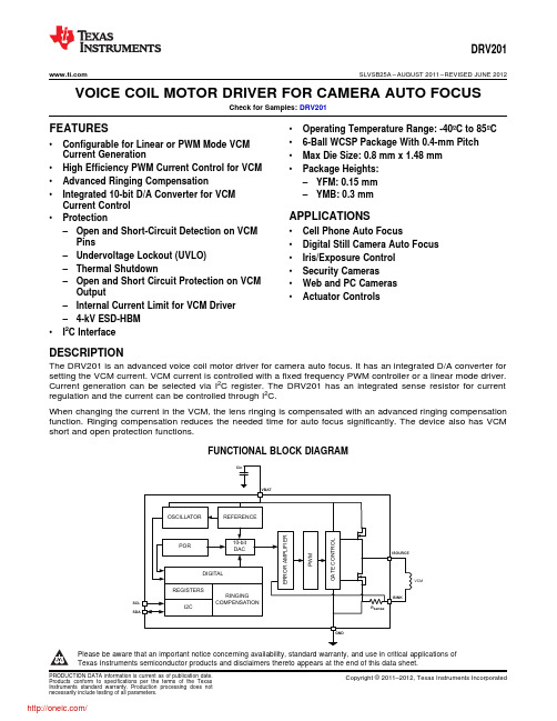
VCMDRV201 SLVSB25A–AUGUST2011–REVISED JUNE2012 VOICE COIL MOTOR DRIVER FOR CAMERA AUTO FOCUSCheck for Samples:DRV201FEATURES•Operating Temperature Range:-40ºC to85ºC•6-Ball WCSP Package With0.4-mm Pitch •Configurable for Linear or PWM Mode VCMCurrent Generation•Max Die Size:0.8mm x1.48mm•High Efficiency PWM Current Control for VCM•Package Heights:•Advanced Ringing Compensation–YFM:0.15mm•Integrated10-bit D/A Converter for VCM–YMB:0.3mmCurrent ControlAPPLICATIONS•Protection–Open and Short-Circuit Detection on VCM•Cell Phone Auto FocusPins•Digital Still Camera Auto Focus –Undervoltage Lockout(UVLO)•Iris/Exposure Control–Thermal Shutdown•Security Cameras–Open and Short Circuit Protection on VCM•Web and PC CamerasOutput•Actuator Controls–Internal Current Limit for VCM Driver–4-kV ESD-HBM•I2C InterfaceDESCRIPTIONThe DRV201is an advanced voice coil motor driver for camera auto focus.It has an integrated D/A converter for setting the VCM current.VCM current is controlled with a fixed frequency PWM controller or a linear mode driver. Current generation can be selected via I2C register.The DRV201has an integrated sense resistor for current regulation and the current can be controlled through I2C.When changing the current in the VCM,the lens ringing is compensated with an advanced ringing compensation function.Ringing compensation reduces the needed time for auto focus significantly.The device also has VCM short and open protection functions.FUNCTIONAL BLOCK DIAGRAMPlease be aware that an important notice concerning availability,standard warranty,and use in critical applications ofTexas Instruments semiconductor products and disclaimers thereto appears at the end of this data sheet.PRODUCTION DATA information is current as of publication date.Copyright©2011–2012,Texas Instruments Incorporated Products conform to specifications per the terms of the TexasInstruments standard warranty.Production processing does notnecessarily include testing of all parameters.CB A21NanoFree YFM PACKAGE(BOTTOM VIEW)YMB package package markings:YM =YEAR /MONTH DATE CODE D =DAY OF LASER MARK S =ASSEMBLY SITE CODE 0=Pin A1(Filled Solid)NanoFree YMB PACKAGE(TOP VIEW)NanoFree YFM PACKAGE(TOP VIEW)C B A21NanoFree YMB PACKAGE(BOTTOM VIEW)YFM package has no top side markingsDRV201SLVSB25A –AUGUST 2011–REVISED JUNE 2012This integrated circuit can be damaged by ESD.Texas Instruments recommends that all integrated circuits be handled with appropriate precautions.Failure to observe proper handling and installation procedures can cause damage.ESD damage can range from subtle performance degradation to complete device failure.Precision integrated circuits may be more susceptible to damage because very small parametric changes could cause the device not to meet its published specifications.ORDERING INFORMATION (1)T APACKAGE (2)ORDERABLE PART NUMBERYFM DRV201YFMR -40°C to 85°CYMBDRV201YMBR(1)For the most current package and ordering information,see the Package Option Addendum at the end of this document,or see the TI web site at .(2)Package drawings,thermal data,and symbolization are available at /packaging .DEVICE INFORMATIONTERMINAL FUNCTIONSTERMINAL I/ODESCRIPTIONNAME NO.VBAT 2A Power GND 1A GroundI_SOURCE 2B Voice coil positive terminal I_SINK 1B Voice coil negative terminal SCL 2C I I 2C serial interface clock inputSDA1CI/O I 2C serial interface data input/output (open drain)2Submit Documentation FeedbackCopyright ©2011–2012,Texas Instruments IncorporatedProduct Folder Link(s):DRV201DRV201 SLVSB25A–AUGUST2011–REVISED JUNE2012ABSOLUTE MAXIMUM RATINGSover operating free-air temperature range(unless otherwise noted)(1)VALUE UNIT VBAT,ISOURCE,ISOURCE pin voltage range(2)–0.3to5.5VVoltage range at SDA,SCL–0.3to3.6VContinuous total power dissipation Internally limitedθJA Junction-to-ambient thermal resistance(3)130°C/WT J Operating junction temperature-40to125°CT A Operating ambient temperature-40to85°CT stg Storage temperature-55to150°C(HBM)Human body model±4000ESD rating V(CDM)Charged device model±500(1)Stresses beyond those listed under Absolute Maximum Ratings may cause permanent damage to the device.These are stress ratingsonly,and functional operation of the device at these or any other conditions beyond those indicated under Recommended Operating Conditions is not implied.Exposure to absolute maximum rated conditions for extended periods may affect device reliability.(2)All voltage values are with respect to network ground terminal.(3)This thermal data is measured with high-K board(4-layer board).ELECTRICAL CHARACTERISTICSOver recommended free-air temperature range and over recommended input voltage range(typical at an ambient temperature range of25°C)(unless otherwise noted)PARAMETER TEST CONDITIONS MIN TYP MAX UNIT INPUT VOLTAGEV BAT Input supply voltage 2.5 3.7 4.8VV BAT rising 2.2V UVLO Undervoltage lockout threshold VV BAT falling2V HYS Undervoltage lockout hysteresis50100250mV INPUT CURRENTInput supply current shutdown,I SHUTDOWN MAX:V BAT=4.4V0.151µAincludes switch leakage currentsInput supply current standby,includesI STANDBY MAX:V BAT=4.4V120200µAswitch leakage currentsSTARTUP,MODE TRANSITIONS,AND SHUTDOWNt1Shutdown to standby100µst2Standby to active100µst3Active to standby100µst4Shutdown time Active or standby to shutdown0.51ms VCM DRIVER STAGEResolution10bitsI RES Relative accuracy-1010LSB Differential nonlinearity-11Zero code error0mAOffset error At code323mA%of Gain error±3FSR Gain error drift0.30.4%/°COffset error drift0.30.5%/°C I MAX Maximum output current102.3mAI LIMIT Average VCM current limit See(1)110160240mA(1)During short circuit condition driver current limit comparator will trip and short is detected and driver goes into STANDBY and short flagis set high in the status register.Copyright©2011–2012,Texas Instruments Incorporated Submit Documentation Feedback3Product Folder Link(s):DRV201DRV201SLVSB25A–AUGUST2011–REVISED ELECTRICAL CHARACTERISTICS(continued)Over recommended free-air temperature range and over recommended input voltage range(typical at an ambient temperature range of25°C)(unless otherwise noted)PARAMETER TEST CONDITIONS MIN TYP MAX UNIT Minimum VCM code for OPEN andI DETCODE See(2)256mASHORT detectionf SW Switching frequency Selectable through CONTROL register0.54MHz V DRP Internal dropout See(3)0.4VL VCM VCM inductance30150µHR VCM VCM resistance1122ΩLENS MOVEMENT CONTROLt set1Lens settling time±10%error band2/f VCM mst set2Lens settling time±10%error band1/f VCM ms VCM resonance frequency50150Hzf VCM When1/f VCM compensation is used-1010VCM resonance frequency tolerance%When2/f VCM compensation is used-3030LOGIC I/Os(SDA AND SCL)V=1.8V,SCL-4.25 4.25I IN Input leakage currentµAV=1.8V,SDA-11R PullUp I2C pull-up resistors SDA and SCL pins 4.7kΩV IH Input high level See(4) 1.17 3.6VV IL Input low level See(5)00.63Vt TIMEOUT SCL timeout for shutdown detection0.51msR PD Pull down resistor at SCL line500kΩf SCL I2C clock frequency400kHz INTERNAL OSCILLATORf OSC Internal oscillator20°C≤T A≤70°C-33%Frequency accuracy-40°C≤T A≤85°C-55% THERMAL SHUTDOWNT TRIP Thermal shutdown trip point140°C(2)When testing VCM open or short this is the recommended minimum VCM code(in dec)to be used.(3)This is the voltage that is needed for the feedback resistor and high side driver.It should be noted that the maximum VCM resistance islimited by this voltage and supply voltage.E.g.3-V supply maximum VCM resistance is:R VCM=(V BAT–V DRP)/I VCM=(3V-0.4V)/102.3mA=25.4Ω.(4)During shutdown to standby transition V IH low limit is1.28V.(5)During shutdown to standby transition V IL high limit is0.51V.4Submit Documentation Feedback Copyright©2011–2012,Texas Instruments IncorporatedProduct Folder Link(s):DRV201VCMDRV201V inDRV201SLVSB25A –AUGUST 2011–REVISED JUNE 2012PARAMETER MEASUREMENT INFORMATIONList of components:•C in -Panasonic ECJ0EB1A105M •VCM -Mitsumi VCM KAF-V85S60•Actuator size:8.5x 8.5x 3.4(mm)•Lens in the VCM:M6(Pitch:0.35)•Weight:75mg •TTL:4.2mm •FB:1.1mmCopyright ©2011–2012,Texas Instruments Incorporated Submit Documentation Feedback5Product Folder Link(s):DRV201DRV201SLVSB25A–AUGUST2011–REVISED TYPICAL CHARACTERISTICSFigure1.Lens Positions With and Without Ringing Figure2.Lens Positions With and Without RingingCompensation With100-µm Step on the Lens Position Compensation With100-µm Step on the Lens Position,Zoomed InFigure3.Lens Positions With and Without Ringing Figure4.Lens Positions With and Without RingingCompensation With30-µm Step on the Lens Position Compensation With30-µm Step on the Lens Position,Zoomed In6Submit Documentation Feedback Copyright©2011–2012,Texas Instruments IncorporatedProduct Folder Link(s):DRV201Vbat ISC/SCLmodeDAC DRV201 SLVSB25A–AUGUST2011–REVISED JUNE2012FUNCTIONAL DESCRIPTIONThe DRV201is intended for high performance autofocus in camera modules.It is used to control the current in the voice coil motor(VCM).The current in the VCM generates a magnetic field which forces the lens stack connected to a spring to move.The VCM current and thus the lens position can be controlled via the I2C interface and an auto focus function can be implemented.The device connects to a video processor or image sensor through a standard I2C interface which supports up to 400-kbit/s data rate.The digital interface supports IO levels from1.8V to3.3V.All pins have4-kV HBM ESD rating.When SCL is low for at least0.5ms,the device enters SHUTDOWN mode.If SCL goes from low to high the driver enters STANDBY mode in less than100μs and default register values are set as shown in Figure5. ACTIVE mode is entered whenever the VCM_CURRENT register is set to something else than zero.Figure5.Power Up and Down SequenceVCM current can be controlled via an I2C interface and VCM_CURRENT registers.Lens stack is connected to a spring which causes a dampened ringing in the lens position when current is changed.This mechanical ringing is compensated internally by generating an optimized ramp whenever the current value in the VCM_CURRENT register is changed.This enables a fast autofocus algorithm and pleasant user experience.Current in the VCM can be generated with a linear or PWM control.In linear mode the high side PMOS is configured as a current source and current is set by the VCM_CURRENT control register.In PWM control the VCM is driven with a half bridge driver.With PWM control the VCM current is increased by connecting the VCM between V BAT and GND through the high side PMOS and then released to a‘freewheeling’mode through the sense resistor and low side NMOS.PWM mode switching frequency can be selected from0.5MHz up to4MHz through a CONTROL register.PWM or linear mode can be selected with the PWM/LIN bit in the MODE register.Copyright©2011–2012,Texas Instruments Incorporated Submit Documentation Feedback7Product Folder Link(s):DRV201DRV201SLVSB25A–AUGUST2011–REVISED MODES OF OPERATIONSHUTDOWN If the driver detects SCL has a DC level below0.63V for duration of at least0.5ms,the driver will enter shutdown mode.This is the lowest power mode of operation.The driver will remain in shutdown for as long as SCL pin remain low.STANDBY If SCL goes from low to high the driver enters STANDBY mode and sets the default register values.In this mode registers can be written to through the I2C interface.Device will be in STANDBY mode when VCM_CURRENT register is set to zero.From ACTIVE mode the device will enter STANDBY if theSW_RST bit of the CONTROL register is set.In this case all registers will be reset to default values.STANDBY mode is entered from ACTIVE mode if any of the following faults occur:Overtemperature protection fault(OTPF),VCM short(VCMS),or VCM open(VCMO).WhenSTANDBY mode is entered due to a fault condition current register is cleared.ACTIVE The device is in ACTIVE mode whenever the VCM_CURRENT control is set to something else than zero through the I2C interface.In ACTIVE mode VCM driver output stage is enabled all the time resulting in higher power consumption.The device remains in active mode until the SW_RST bit in the CONTROL register is set,SCL is pulled low for duration of0.5ms,VCM_CURRENT control is set to zero,or any of the following faults occur:Over temperature protection fault(OTPF),VCM short(VCMS),or VCM open (VCMO).If active mode is entered after fault the status register is automatically cleared.8Submit Documentation Feedback Copyright©2011–2012,Texas Instruments IncorporatedProduct Folder Link(s):DRV201DRV201 SLVSB25A–AUGUST2011–REVISED JUNE2012VCM DRIVER OUTPUT STAGE OPERATIONCurrent in the VCM can be controlled with a linear or PWM mode output stage.Output stage is enabled in ACTIVE mode which can be controlled through VCM_CURRENT control register and the output stage mode is selected from MODE register bit PWM/LIN.In linear mode the output PMOS is configured to a high side current source and current can be controlled from a VCM_CURRENT registers.In PWM control the VCM is driven with a half bridge driver.With PWM control the VCM current is increased by connecting the VCM between V BAT and GND through the high side PMOS and then released to a‘freewheeling’mode through the sense resistor and low side NMOS.Current in the VCM is sensed with a1-Ωsense resistor which is connected into an error amplifier input where the other input is controlled by the10-bit DAC output. PWM mode switching frequency can be selected from0.5MHz up to4MHz through a CONTROL register.PWM or linear mode can be selected with the PWM/LIN bit in the MODE register.RINGING COMPENSATIONVCM current can be controlled via an I2C interface and VCM_CURRENT registers.Lens stack is connected to a spring which causes a dampened ringing in the lens position when current is changed.This mechanical ringing is compensated internally by generating an optimized ramp whenever the current value in the VCM_CURRENT register is changed.This enables a fast auto focus algorithm and pleasant user experience.Ringing compensation is dependent on the VCM resonance frequency and this can be controlled via VCM_FREQ register(07h)from50Hz up150Hz.Table1shows the VCM_FREQ register setting for each resonance frequency in1-Hz steps.If more accurate resonance frequency is available,the control value can be calculated with Equation1.Ringing compensation is designed in a way that it can tolerate±30%frequency variation in the VCM resonance frequency when2/f VCM compensation is used and±10%variation with1/f VCM so only statistical data from the VCM is needed in production.Copyright©2011–2012,Texas Instruments Incorporated Submit Documentation Feedback9Product Folder Link(s):DRV201DRV201SLVSB25A–AUGUST2011–REVISED Table1.VCM Resonance Frequency Control Register(07h)Table VCM VCM_FREQ[7:0](07h)VCM VCM_FREQ[7:0](07h)VCM VCM_FREQ[7:0](07h) Resonance Resonance ResonanceFrequency Frequency FrequencyDEC BIN DEC BIN DEC BIN [Hz][Hz][Hz]50008415410011010118220110111005171118515710011101119222110111105214111086160101000001202231101111153211010187162101000101212241110000054271101188165101001011222261110001055341000108916710100111123227111000115640101000901701010101012422811100100574610111091172101011001252291110010158521101009217410101110126231111001115958111010931771011000112723211101000606311111194179101100111282331110100161681000100951811011010112923411101010627310010019618310110111130235111010116378100111097185101110011312361110110064831010011981871011101113223811101110658810110009918910111101133239111011116692101110010019110111111134240111100006796110000010119311000001135241111100016810111001011021951100001113624211110010691051101001103197110001011372431111001170109110110110419811000110138244111101007111311100011052001100100013924511110101721161110100106202110010101402461111011073120111100010720411001100141247111101117412411111001082051100110114224811111000751271111111109207110011111432491111100176130100000101102081101000014425011111010771341000011011121011010010145251111110117813710001001112212110101001462511111101179140100011001132131101010114725211111100801431000111111421511010111148253111111018114610010010115216110110001492541111111082149100101011162171101100115025511111111831521001100011721911011011---10Submit Documentation Feedback Copyright©2011–2012,Texas Instruments IncorporatedProduct Folder Link(s):DRV201分销商库存信息:TIDRV201YFMT DRV201YFMR DRV201EVM。
TPL7407L高压低侧驱动器说明书
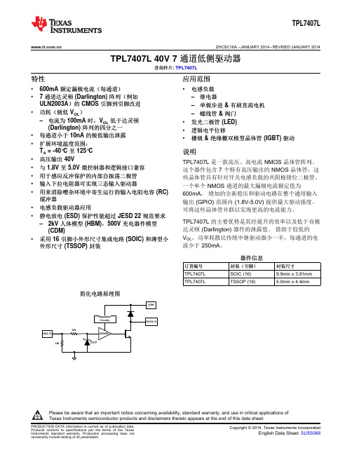
TPL7407L ZHCSC16A–JANUARY2014–REVISED JANUARY2014TPL7407L40V7通道低侧驱动器查询样片:TPL7407L特性应用范围•600mA额定漏极电流(每通道)•电感负载•7通道达灵顿(Darlington)阵列(例如–继电器ULN2003A)的CMOS引脚到引脚改进–单极步进&有刷直流电机•功耗(极低V OL)–螺线管&阀门–电流为100mA时,V OL低于达灵顿•发光二极管(LED)(Darlington)阵列的四分之一•逻辑电平位移•每通道小于10nA的极低输出泄露•栅极&绝缘栅双极型晶体管(IGBT)驱动•扩展环境温度范围:T A=-40°C至125°C说明•高压输出40V TPL7407L是一款高压、高电流NMOS晶体管阵列。
•与1.8V至5.0V微控制器和逻辑接口兼容这个器件包含7个特有高压输出的NMOS晶体管,这•用于感应反冲保护的内部自振荡二极管些晶体管具有针对开关电感负载的共阴极钳位二极管。
•输入下拉电阻器可实现三态输入驱动器一个单个NMOS通道的最大漏极电流额定值为•用来消除嘈杂环境中寄生运行的输入电阻电容(RC)600mA。
增加的全新稳压和驱动电路在整个通用输入缓冲器输出(GPIO)范围内(1.8V-5.0V)提供最大驱动强度。
•电感负载驱动器应用可将这些晶体管并联以实现更高的电流能力。
•静电放电(ESD)保护性能超过JESD22规范要求TPL7407L的主要优势是其经提升的效率以及低于双极–2kV人体模型(HBM),500V充电器件模型达灵顿(Darlington)器件的泄露值。
借助于较低的(CDM)V OL,功率耗散比传统中继驱动器少一半,每通道的电•采用16引脚小外形尺寸集成电路(SOIC)和薄型小流少于250mA。
外形尺寸(TSSOP)封装器件信息订货编号封装(引脚)封装尺寸TPL7407L SOIC(16)9.9mm x3.91mmTPL7407L TSSOP(16) 5.0mm x4.4mm 简化电路原理图Please be aware that an important notice concerning availability,standard warranty,and use in critical applications ofTexas Instruments semiconductor products and disclaimers thereto appears at the end of this data sheet.TPL7407L TSSOP/SOICTPL7407LZHCSC16A –JANUARY 2014–REVISED JANUARY 2014These devices have limited built-in ESD protection.The leads should be shorted together or the device placed in conductive foam during storage or handling to prevent electrostatic damage to the MOS gates.TERMINAL CONFIGURATION AND FUNCTIONSTerminal FunctionsTERMINALDESCRIPTIONNAME NUMBER IN(X)1,2,3,4,5,6,7GPIO inputs that will drive the outputs "low"(or sinnk current)when driven "high"16,15,14,13,12,11,OUT(X)Driver output that sinks currents after input is driven "high"10COM 9Supply PIn that should be tied to 8.5V or higher for proper operation GND8Ground pinSpecificationsAbsolute Maximum Ratings (1)at 25°C free-air temperature (unless otherwise noted)MINMAX UNIT V OUT Pins OUT1-OUT7to GND voltage -0.342V V OK Ouput Clamp diode reverse voltage (2)-0.342V V COM COM pin voltage (2)-0.342V V IN Pins IN1-IN7to GND voltage (2)-0.330V I DS Continuous drain current per channel (3)(4)600mA I OK Output clamp current500mA I GND Total continuous GND-terminal current –2A T A Operating free-air temperature range –40125°C T J Operating virtual junction temperature -40150°C T stg Storage temperature range–65150°C(1)Stresses beyond those listed under "absolute maximum ratings"may cause permanent damage to the device.These are stress ratings only,and functional operation of the device at these or any other conditions beyond those indicated under "recommended operating conditions"is not implied.Exposure to absolute-maximum-rated conditions for extended periods may affect device reliability.(2)All voltage values are with respect to the GND/substrate terminal,unless otherwise noted.(3)Maximum power dissipation is a function of T J (max),θJA ,and T A .The maximum allowable power dissipation at any allowable ambient temperature is P D =(T J (max)–T A )/θJA .Operating at the absolute maximum T J of 150°C can affect reliability.(4)The package thermal impedance is calculated in accordance with JESD 51-7.TPL7407L ZHCSC16A–JANUARY2014–REVISED JANUARY2014Thermal InformationTPL7407LTHERMAL METRIC(1)SOIC(D)TSSOP(PW)UNIT16PINS16PINSθJA Junction-to-ambient thermal resistance91.9115.2°C/WθJCtop Junction-to-case(top)thermal resistance50.149.5°C/WθJB Junction-to-board thermal resistance49.460.8°C/WψJT Junction-to-top characterization parameter18.68.5°C/WψJB Junction-to-board characterization parameter49.160.2°C/WθJCbot Junction-to-case(bottom)thermal resistance N/A N/A°C/W (1)For more information about traditional and new thermal metrics,see the IC Package Thermal Metrics application report,SPRA953.Recommended Operating ConditionsOver operating temperature rangeMIN NOM MAX UNITV OUT OUT1-OUT7pin voltage for recommended operation040VV COM COM pin voltage range for full output drive8.540VV IL IN1-IN7input low voltage("Off"high impedance output)0.9VV IH IN1-IN7input high voltage("Full Drive"low impedance output) 1.5VT J Operating virtual junction temperature-40125°CI DS Continuous drain current0500mAElectrical CharacteristicsT J=–40°C to125°C;Typical Values at T A=T J=25°CPARAMETER TEST CONDITIONS MIN TYP MAX UNITV IN≥1.5V I D=100mA200320 OUT1-OUT7low-level outputV OL(V DS)mV voltage I=200mA420650DI OUT(OFF)(I DS_OFF)OUT1-OUT7OFF-state leakage V OUT=24V,V IN≤1.0V10500nAcurrentV F Clamp forward voltage I F=200mA 1.4VI IN(off)IN1-IN7Off-state input current V INX=0V V OUT=40V500nAI IN(ON)IN1-IN7ON state input current V INX=1.5V-5.0V10μAI COM Static current flowing through COM V COM=8.5V-40V1525μApinSwitching CharacteristicsTypical Values at T A=T J=25°CPARAMETER TEST CONDITIONS MIN TYP MAX UNITPropagation delay time,low-to high-level350t PLH V INX≥1.65V,Vpullup=24V,Rpull-up=48Ωns outputPropagation delay time,high-to low-level350t PHL V INX≥1.65V,Vpullup=24V,Rpull-up=48Ωns outputC i Input capacitance V I=0,f=100KHz5pFTPL7407LZHCSC16A–JANUARY2014–REVISED Typical CharacteristicsOL DS(TSSOP)Cycle at25°C Cycle at70°CTPL7407L ZHCSC16A–JANUARY2014–REVISED JANUARY2014Typical Characteristics(continued)Cycle at25°C Cycle at70°C()J(MAX)A (MAX)JAT T PD -=q ND OLi Lii 1P V I ==´åTPL7407LZHCSC16A –JANUARY 2014–REVISED JANUARY 2014APPLICATION AND IMPLEMENTATIONTTL and other Logic InputsTPL7407L input interface is specified for standard 1.8V and 5V CMOS logic interface and can tolerate up to 30V.At any input voltage the output drivers will be driven at it's maximum when Vcom is greater than or equal to 8.5V.Input RC SnubberTPL7407L features an input RC snubber that helps prevent spurious switching in noisy environment.Connect an external 1k Ωto 5k Ωresistor in series with the input to further enhance TPL7407L’s noise tolerance.High-impedance Input DriversTPL7407L features a 1M Ωinput pull-down resistor.The presence of this resistor allows the input drivers to be tri-stated.When a high-impedance driver is connected to a channel input the TPL7407L detects the channel input as a low level input and remains in the OFF position.The input RC snubber helps improve noise tolerance when input drivers are in the high-impedance state.On-chip Power DissipationUse the below equation to calculate TPL7407L on-chip power dissipation P D :Where:N is the number of channels active together.V OLi is the OUT i pin voltage for the load current I Li .(1)Thermal ReliabilityIt is recommended to limit TPL7407L IC’s die junction temperature to less than 125°C.The IC junction temperature is directly proportional to the on-chip power e the following equation to calculate the maximum allowable on-chip power dissipation for a target IC junction temperature:Where:T J(MAX)is the target maximum junction temperature.T A is the operating ambient temperature.θJA is the package junction to ambient thermal resistance.(2)Improving Package Thermal PerformanceθJA value depends on the PC board layout.An external heat sink and/or a cooling mechanism,like a cold air fan,can help reduce θJA and thus improve device thermal capabilities.Refer to TI’s design support web page at /thermal for a general guidance on improving device thermal performance.TPL7407L ZHCSC16A–JANUARY2014–REVISED JANUARY2014 Application ExamplesUnipolar Stepper Motor DriverFigure9shows an implementation of TPL7407L for driving a uniploar stepper motor.The unconnected input channels can be used for other functions.When an input pin is left open the internal1MΩpull down resistor pulls the respective input pin to GND potential.For higher noise immunity use an external short across an unconnected input and GND pins.The COM pin must be tied to the supply of whichever inductive load is being driven for the driver to be protected by the free-wheeling diode.Figure9.TPL7407L as a Stepper Motor DriverTPL7407LZHCSC16A–JANUARY2014–REVISED Multi-Purpose Sink DriverWhen configured as per Figure10TPL7407L can be used as a multi-purpose driver.The output channels can be tied together to sink more current.TPL7407L can easily drive motors,relays&LEDs with little power dissipation. COM must be tied to highest load voltage,which may or may not be same as inductive load supply.VSUPFigure10.TPL7407L Multi-Purpose Sink Driver ApplicationTPL7407L ZHCSC16A–JANUARY2014–REVISED JANUARY2014 24V Relay DriverTo drive lower resistance relays,like<48Ω,connect two or more adjacent channels in parallel as shown in Figure11.Connecting several channels in parallel lowers the channel output resistance and increases the drive current.TPL7407L can be used for driving12V,24V&36V relays with similar a implementation.Figure11.TPL7407L Driving24V RelaysTPL7407LZHCSC16A–JANUARY2014–REVISED REVISION HISTORYChanges from Original(January2014)to Revision A Page •初次发布完整版本。
- 1、下载文档前请自行甄别文档内容的完整性,平台不提供额外的编辑、内容补充、找答案等附加服务。
- 2、"仅部分预览"的文档,不可在线预览部分如存在完整性等问题,可反馈申请退款(可完整预览的文档不适用该条件!)。
- 3、如文档侵犯您的权益,请联系客服反馈,我们会尽快为您处理(人工客服工作时间:9:00-18:30)。
DRV8825
(2.5A @ 8.2 to 45V) 1/32-ustep
On-chip current regulation
Up to 32-steps (indexers)
DRV8812
(1.6A @ 8.2 – 45V)
DRV8813
(2.5A @ 8.2 – 45V)
MCU needed for stepping 0 to > 256 stepping supported Battery power target apps On-chip current regulation Low sleep currents 8834 has 32-step indexer
8x
Back to Main Previous Families
TI’s DRV8x Motor Drivers
Support up to 60V/60A
• 2.0V to 60V; Up to 12A Precise Position Control
Stepper Drivers
• Up to 32 u-steps indexer support • Up to 256 u-steps & greater w/ external ref • Indexer, phase enable, PWM, & serial ctrl • 2.0V to 60V; Up to 24A Simplicity & Low Cost
8x
Back to Main Previous Families
OCP Implementation – Analog (DRV88xx)
Ovecurrent Detect OVERCURRENT (to digital)
COMP
VREF
+
PRE_DRIVE
+
AMP
VM
Coupled
HS_ON (from digital)
Fault Pin
Short circuit occurs
After a deglitch of ~ 3uS, outputs are tristated
Winding current
Enable pin
8x
Back to Main Previous Families
DRV8x – Mass Market Portfolio
3-Phase Brushless Drivers
• Pre-Drivers support up to 60A • Integrated current sense amps / buck
• PWM and Clock ctrl
8x
Back to Main Previous Families
DRV8x Family Features
High current / performance Integrated drivers
DRV8301
(60A / 60V / SPI Ctrl) Buck + 2x Sense Amps
DRV8302
(60A / 60V / HW Ctrl) Buck + 2x Sense Amps
Drive external FETs up to 60A Integrates 1.5A buck and 2x amps C2000, MSP430, ARM MCU Kits
P2P Compatible
DRV8833
(4A @ 2.7 – 10.8V)
Voltage regulation
Low Voltage
Production
DRV8835
(3A @ 2 – 11V)
Sampling
8x
Back to Main
Previous
Families
FEATURED PRODUCTS
Motor Drive Business Unit
New Market
– – – – – – – – – DRV92250 in HV fan(ceiling fan and white goods fan) DRV9 for small white good application DRV91680/70 for power tools DRV9x for BDC power tools(Integrated with 8051, it is ongoing ) DRV8313 +MSP430G for 24V/36v Fan Gas water heater fan and other 24V Fan DRV8 for Automotive application.(Driver for Window, Door, Seat, Lighting) DRV11873 for 12v BLDC motor and water pump DRV10973 for 24V BLDC motor DRV201 for smart phone camera module: Truly, Foxconn.
Configuring Itrip
M
VREF ITRIP GAIN RSENSE
Winding Current
In Volts (V)
RSENSE
Amp
Reference Voltage
IMAX
VREF
To H Bridge Enable
Low Side Current Sensing
8x
Back to Main Previous Families
FEATURED PRODUCTS
Brushed DC Motor Drivers
DRV8412 DRV8432
(24A @ 0 – 50V)
High Current / High Performance Up to 500kHz PWM
•
Shenzhen regional main opportunities: – 1: Motor manufactory – 2: Fan – 3:Whitegoods. – 4: Industry in Guangzhou region: Gambling machine, Tooth doctor operator(Fu shang); Curve machine; Package machine; Fan customer.
Brushless DC Motor Drivers
DRV8332
(13A @ 0 – 50V)
DRV8312
(6.5A @ 0 – 50V)
High Current / High Performance
Up to 500kHz PWM As low as 5ns dead time C2000, MSP430, ARM Kits
• Reduced Board Space / BOM • Improved Reliability • No discrete design experience needed. Just drop in and spin. • Minimal MCU support required
Fully Integrated Solutions
DRV8811
(1.9A @ 8 to 38V) 1/8 -ustep
DRV8818
(2.5A @ 8 to 35V) 1/8 -ustep
C2000, MSP430, ARM MCU Kits No MCU needed for stepping
DRV8824
(1.6A @ 8.2 to 45V) 1/32-ustep
Embedded Intelligence
• Basic to advanced commutation engines
• Digital control loops • Over current / Short circuit protection
CURRENT
Robust, Reliable & • Thermal protection Fully Protected
Brushed DC Drivers
• Inrush current protection • Brake and Coast support • Phase enable, PWM , and serial ctrl • 8 to 60V; Up to 13A Reliability & Efficiency
Stepper Motor Drivers
DRV8412
(6A @ 0 – 50V)
DRV8432
(12A @ 0 – 50V)
High Current / High Performance Up to 500kHz PWM
High current / performance
Up to 97% Efficient
(12A @ 0 – 50V)
Single or Dual
Single or Dual
High Current / performance
DRV8802
(1.6A @ 8.2 – 45V)
Up to 97% Efficient
C2000, MSP430, ARM MCU Kits
DRV8814
(2.5A @ 8.2 – 45V)
Hale Waihona Puke OUTPUT FET+
AMP
Analog Ilimit
OUT
Critical Points:
Analog OCP implementation (high side shown)
Two analog components of OCP: