建伍TM-441A简易使用说明
KENWOOD健伍TM241A说明

健伍TM-241A/441A中文操作说明由原版英文说明书翻译而得13845257.目录1 使用前的注意事项 (4)2 规格参数 (6)3 随机附件 (7)4 安装 (8)5 操作控制部件及功能 (10)接收接收 (16)频率选择 (17)频率步长选择 (17)可编程频率方式(VFO)调谐限制 (18)ALT(仅对TM-541A/E有效) (19)发射 (20)超时定时器(TOT) (20)存储器后备电池 (21)初始状态 (21)初始化 (21)存储信道 (21)存储目录 (22)存储信道的存入 (22)存储信道的调出 (24)存储转移 (24)扫描扫描 (25)挂起/恢复 (25)频段扫描 (26)可编程频段扫描 (26)存储信道扫描 (27)存储信道跳过 (27)优先信道报警 (28)使用中继频差设定 (28)倒频功能 (29)亚音 (29)亚音频率选择 (29)自动补偿(仅对美国版有效) (30)连续单音静噪(CTCSS) (30)双音频静噪(DTSS) (31)数字录音(DRS) (34)分组 (41)音频报警 (47)自动关闭电源(APO) (48)屏幕背光(DIM) (48)提示音 (49)按键锁定 (49)6 电路图7 维修 (50)8 可选附件 (52)2 规格参数5 操作5-1-1 控制部件及功能①电源开关(POWER)接通或关闭电源。
按下VFO键或MR键同时接通电源将清除频率方式或存储信道的频率信息。
当电源接通时,手柄上的PF键可以编程。
②调谐旋钮选择发射或接收频率、存储信道、频率步长、亚音频率、扫描方向等。
③音量旋钮(VOL)调整扬声器的音量,顺时针方向转动将增大音量,逆时针方向转动减小音量。
④静噪旋钮(SQL)选择静噪阀值。
⑤功率/背光键(LOW/DIM)功率选择发射输出功率的大小(HI:高,MID:中,LOW:低)背光选择显示屏幕的背光亮度。
按住功能键(F)1秒钟以上,当F 显示闪烁时再按此键将开启或关闭超时定时器。
健伍系列对讲机编程手册及操作说明
健伍系列对讲机编程手册及操作说明2007-11-24 20:26健伍系列对讲机编程手册及操作说明今天在网上闲逛,发现这篇好东东,发上来分享下:KENWOOD TH42对讲机简易使用说明三种工作模式:1,VFO模式(频率工作模式)2,MR模式(信道模式)3,CALL模式(呼叫信道,类似普通信道模式)三种工作模式转换:分别按VFO,MR,CALL键VFO模式可以用键盘直接输入工作频率,也可以用频道旋钮改变工作频率。
频率步进选择:短按F键,再按T键,屏幕显示频率步进数值,用频道旋钮选择需要的步进频率。
普通模式:收发频率相同差频工作模式:发射频率比接收频率高或低一个设定的频率差频方向设定:短按F键,再按REV键,屏幕显示+,表示发射频率比接收频率高设定的频率。
重复上述操作,屏幕显示“-”,表示发射频率比接收频率低设定的频率重复上述操作,回到普通模式。
设定频差:长按F键,再按REV键,屏幕显示频差,用频道旋钮改变频差MR模式如何将频率存入信道?在VFO模式调好频率和频差,长按F键,屏幕右上脚显示频道数,用频道旋钮选择希望贮存的频道,再按MR键,频率即存入。
如何在一个频道中分别存贮发射和接收频率?应该先存入接收频率,再存入发射频率在VFO模式调好接收频率,长按F键,屏幕右上脚显示频道数,用频道旋钮选择希望贮存的频道,再按MR键,接收频率即存入。
在VFO模式调好发射频率,长按F键,屏幕右上脚显示频道数,用频道旋钮选择希望贮存的频道,按住PTT键不放的同时再按MR键,发射频率即存入。
CALLA模式如何将频率存入CALL信道?方法同存入MR信道基本相同,只是将上述的MR改为CALL即可。
亚音频:42A已经内置标准亚音频编码功能,解码功能需安装选件短按T键,屏幕显示T,亚音频编码功能启用再按T键,屏幕显示CT,亚音频编解码功能启用再按T键,亚音频功能不启用。
长按F键,再按T键,屏幕显示亚音频频率,用频道旋钮选择需要的频率扫描:频率扫描:长按VFO键频道扫描:长按MR键其它功能改变发射功率:短按F键,再按PTT键,可以循环选择大,小,微功率(屏幕显示为H,L,EL)照明灯长亮:短按F键,再按LAMP键调节静噪深度:短按F键,再按SQL键,用频道旋钮调整静噪深度。
Le Grand 441M 无线电信号源说明书

O 1672B -01P C -12W 48}}· CARATTERISTICHE TECNICHETensione di alimentazione dal BUS18 – 27 VdcAssorbimento (alimentazione dal BUS) Assorbimento stand-by 5 mAAssorbimento in funzionamento con retroilluminazione spenta13 mAAssorbimento in funzionamento con retroilluminazione e LED accesi20 mATemperatura di funzionamento0 – 50 °C · TECHNICAL FEATURESSupply voltage from the BUS18 – 27 VdcAbsorption(supplied by the BUS)Absorption stand-by 5 mAAbsorption during operation withbacklight off13 mAAbsorption during operation withbacklight and LEDs on20 mA Operating temperature0 – 50 °C· TECHNISCHE EIGENSCHAFTENSpeisespannung vom BUS18 – 27 VdcStromaufnahme(Speisung vom BUS)Standby 5 mAStromaufnahme bei ausgeschalteterRückbeleuchtung13 mAStromaufnahme bei eingeschalteterRückbeleuchtung und leuchtendenLEDs20 mA Betriebstemperatur0 – 50 °C· TECHNISCHE GEGEVENSVoedingsspanning via de Bus18 – 27 VdcStroomopname(voeding via de bus)Standby 5 mAOpname tijdens de functioneringmet uitgeschakelde verlichting13 mAOpname tijdens de functioneringmet ingeschakelde verlichting enbrandende leds20 mA Bedrijfstemperatuur0 – 50 °C· ΤΕΧΝΙΚΑ ΧΑΡΑΚΤΗΡΙΣΤΙΚΑΤάση τροφοδοσίας από τον BUS18 – 27 VdcΑπορρόφηση(τροφοδοσία από τονBUS)Απορρόφηση stand-by 5 mAΑπορρόφηση σε λειτουργία με τονοπισθοφωτισμό απενεργοποιημένο13 mAΑπορρόφηση σε λειτουργία μετον οπισθοφωτισμό και τα LEDενεργοποιημένα20 mA Θερμοκρασία λειτουργίας0 – 50 °C· CARACTÉRISTIQUES TECHNIQUESTension d’alimentation sur BUS18 – 27 VdcAbsorption (alimentation sur BUS)Stand-by 5 mAAbsorbation en fonctionnementavec rétro-éclairage éteint13 mAAbsorbation en fonctionnementavec rétro-éclairage et VOYANTSallumés20 mATempérature de fonctionnement0 – 50 °C· CARACTERÍSTICAS TÉCNICASTensión de alimentación desde el BUS18 – 27 VdcPotencia absorbida (alimentación de el BUS)Corriente absorbida en standby 5 mA Corriente absorbida enfuncionamiento conretroiluminación apagada13 mACorriente absorbida enfuncionamiento conretroiluminación y LEDS encendidos20 mATemperatura de funcionamiento0 – 50 °C· CARACTERÍSTICAS TÉCNICASTensão de alimentação do BUS18 – 27 VdcAbsorção (alimentação do BUS)Stand-by 5 mAAbsorção em funcionamento comiluminação por trás apagada13 mAAbsorção em funcionamento comiluminação por trás e LED acesos20 mATemperatura de funcionamento0 – 50 °C· TEKNİK VERİLER BUS besleme gerilimi18 – 27 Vdc Tüketim (BUS)Assorbimento stand-by5 mAEkran ışığı kapalıken tüketim 13 mAEkran ışığı yanıyorken tüketim 20 mAÇalışma sıcaklığı0 – 50 °C· 技术特征总线电源电压18 – 27 Vdc 吸收电流(总线电源)待机时的吸收电流5 mA背光关闭工作时的吸收电流13 mA背光打开和LED灯亮起工作时20 mA工作温度0 – 50 °C· DANE TECHNICZNENapięcie zasilania z magistrali (BUS)18 – 27 Vdc Pochłanianie(zasilanie z magistrali)Pochłanianie stand-by 5 mAPochłanianie podczasfunkcjonowania z wygaszonym podświetleniem13 mAPochłanianie podczasfunkcjonowania z podświetleniem i diodami LED włączonymi20 mA Temperatura robocza0 – 50 °C · ТЕХНИЧЕСКИЕ ХАРАКТЕРИСТИКИНапряжение питания от шины18 – 27 В постоянноготокаПотребление(питание от шины)Потребление в режиме ожидания 5 мАПотребление при работе с выключенной подсветкой13 мАПотребление при работе с включенной подсветкой20 мАРабочая температура0 – 50 °C。
建伍对讲机部分机型写频方法机对讲机使用注意事项
■建伍对讲机部分机型写频方法TK3118调频率方法1.按住MONI键+DIAL键开机至显示SELF;2.按一下LOW显CH1,转动频道旋钮"ENC"选择所需信道;3.按一下PTT键显------2,按一下LOW键显示接收频率,按住 "1"键转动频道旋钮"ENC"调整数,松开 "1"键转动频道旋钮"ENC"调小数,按PTT键直到显示-------4,按一下LOW显示出发射频率,调整方法与调整接收频率相同。
按PTT键直到显示CH2。
此时一信道已存好。
4.选择其他信道的设置,请重复以上的步骤。
按FUNC显示SELF,关机---ok!■TK3118调选呼方法写完频率,调至(可选信令),选择DTMF,调至于》》3符号,显示频道编辑---频道1。
选择第六项,XP不静音选择(载波+DTMF)点击确认。
点击编缉,选择DTMF(双音多频)(D),点击编缉,选择DTMF键制式或(12键或16键)点确认。
点解码,选择:DTMF信令。
选择呼叫中间代码 #组代码关:选择(ABCD*#)呼叫报警常规或连续自动应答自动复位定时器(妙)ID代码输入自身码■TK3118调VOX方法1.开机;2.长按FUNC两秒至"F"闪烁;3.按"LOW"---VOX闪烁;4.旋钮选择等级,建议设置为1,不然延时过长。
■TK208-308调频方法1. 清频:按住PTT+CSET+开机;2. 写频:按MONI,液晶板上显示的频点大数150.00闪动,此时调出所需的频点,按一下CSET选择信道数,为第一频01开始),按一下CSET存入接收频点;3. 若发射为异频时再按一下MONI先调出发射频点,按住PTT键不放,按两下CSET和REV显示+.-4. 显示CH状态:按住PTT键和REV键开机;5. 查看频:按住PTT+CTCSS开机,再按一下LOW即可进入维修模式。
Motor Insight C441 DeviceNet接口模块操作手册说明书

Application of DeviceNet and Motor InsightHow to Control and Monitor a C441 Motor Insight via DeviceNet Application:The purpose of this application example is to demonstrate how to control and monitor a Motor Insight motor protection relay from a DeviceNet scanner. The DeviceNet interface module for the Motor Insight contains 4 inputs and 2 outputs. One of the outputs is used to control the contactor via the normally closed fault relay contact (95/96 contact) on the Motor Insight. The Motor Insight provides a high level of protection for the motor and will not close the fault relay contact (de-energize the fault relay) if any condition exists that could damage the motor. It will also open the fault relay contact should such a condition occur while the motor is running.This application example does not use any particular DeviceNet scanner, but provides information for configuring one of the C441K/L DeviceNet interface modules to be polled by a DeviceNet scanner. Rockwell’s RSNetworx DeviceNet commissioning software is used in this application example because it is the most common DeviceNet commissioning software. The difference between the C441K andC441L is that the K module has 120vac inputs and the L module has 24vdc inputs. Both modules have 4 inputs and 2 relay outputs.Overview:The Motor Insight is a motor protection relay which can be used with any contactor. This application note will show how to wire a Motor Insight to a contactor and will also configure the C441K/L module to be ready to be polled by any DeviceNet scanner. There are numerous data parameters that may be monitored from a Motor Insight including: individual phase currents, average of the three phase currents, individual phase voltages, average of the three phase voltages, motor power, voltage unbalance, current unbalance, power factor, ground fault current, frequency, thermal capacity and a fault queue. This application example will use Input Assembly 110 to monitor 10 different parameters from the Motor Insight and Output Assembly 105 to control it.The following shows the various Input and Output Assemblies for the Motor Insight:Input Assemblies:1.Input Assembly 50: Faulted bit – 1 byte2.Input Assembly 51: Faulted and Warning bits – 1 byte3.Input Assembly 107: Fault and Warning bits along with the status for the 4 inputs and 2 outputs– 1 byte4.Input Assembly 100: Select up to 4 parameters to monitor from Table 1 below – 8 bytes5.Input Assembly 110: Select up to 10 parameters to monitor from Table 1 below – 20 bytes Output Assemblies:1.Output Assembly 2: Fault Reset bit – 1 byte2.Output Assembly 105: Fault Reset bit and control for the 2 outputs – 1 byte3.Output Assembly 111: Bit Strobe Command – Polled data will be used for this example. Referthe Motor Insight user manual (Chapter 8), publication MN04209001E for information on this Output Assembly.Value Description0 RMS Current – Phase IA1 RMS Current – Phase IB2 RMS Current – Phase IC3 Composite I/O Data4 Field Inputs5 RMS Current AVG6 RMS Voltage VAB7 RMS Voltage VBC8 RMS Voltage VCA9 RMS Voltage AVG10 Total KW11 Voltage Unbalance Percent12 Current Unbalance Percent13 Apparent Power Factor14 Residual Ground Current Deciamps15 Frequency16 Overload Thermal Pile17 Trip Reason18 Overload Status19 Error CodeTable 1Control of the contactor is accomplished via a hard-wired output on the Motor Insight’s DeviceNet module. The system controller and its DeviceNet scanner control the output via DeviceNet. This output is wired in series with the N.C. Fault Relay contact (95/96) on the Motor Insight to control the contactor. The controller program energizes an output on the Motor Insight’s DeviceNet module to close the contactor and turns the output off to open the contactor. If a fault occurs, the N.C. Fault Relay contact on the Motor Insight will open and the program will be notified immediately. 10 different parameters are being continuously monitored from the Motor Insight as well. For this example, Input Assembly 110 and Output Assembly 105 will be used.Part Numbers used for this Application Example(1) C441BA 2 - 9A; 200-240VAC (50/60Hz) Motor Insight(1) C441K DeviceNet interface module with I/O for the Motor Insight(1) ContactorDeviceNet Cable, 24vdc power supply and other hardware needed to put together a DeviceNet system. Motor Insight Control Wiring DiagramPer the Control Wiring diagram above, the normally open relay contact across pins 8 and 9 on the DeviceNet Interface module for the Motor Insight DeviceNet module (C441K) is controlled via the DeviceNet network. If the normally closed relay contact (95/96) on the Motor Insight is in its normal state, then the Motor Insight is not tripped and when the output on the C441K is energized, the contactor will energize, starting the motor. The output on the C441K is controlled via DeviceNet by the DeviceNet scanner and the system controller. Input Assembly 110 is used in this example to monitor 10 different parameters and Output Assembly 105 is used to reset the Motor Insight and to control the relay output on the C441K. Terminals 8 & 9 on the C441K is the relay output contact.DeviceNet ConnectionsDeviceNet supports two methods for connecting devices to the network. Daisy-chain and trunk-line / drop-line are the two network topologies allowed for DeviceNet. For this example, trunk-line / drop-line is used, with a drop for each of the following devices:1.DeviceNet scanner2.C441K Motor Insight DeviceNet module with 120vac I/O3.24vdc network power supplyNote: Be sure to terminate both physical ends of the DeviceNet trunk cable with 121-Ohm, 1%, ¼ watt metal film termination resistors.Configuring the Motor Insight for DeviceNet CommunicationsPlease refer to the Motor Insight module’s user manual, publication MN04209001E for information on configuring your Motor Insight for the motor it will be protecting and other features. The DeviceNet Interface module for the Motor Insight is discussed in Chapter 8 of that manual. It is configured for Baud Rate and MAC ID with dip switches located on the module. For this example, 125K Baud and MAC ID 1 will be used for the Motor Insight. Connect the DeviceNet Interface module to the Motor Insight. Before applying power, set the dip switches. The state of the 8 dip switches for this application example are:Switch Number Setting1OFF2OFF3OFF4OFF5OFF6OFF7OFF8ONDip Switches 1 and 2 set the baud rate. Both OFF indicates 125K baud. Switch 1 OFF and 2 ON indicates 250K baud and both switches ON indicates 500K baud. Dip Switches 3-8 set the MAC ID of the device. These switches are set using weighted binary. In other words, switch 8 has a value of 1, switch 7 a value of 2, switch 6 a value of 4 and so on. Then, add the weighted values of all switches that are ON to obtain the MAC ID.Power the Motor Insight. It is now configured to be MAC ID 1 at 125K baud on DeviceNet. Configuring the C441K/L Module for Selected I/O AssembliesAny valid DeviceNet commissioning software may be used to configure the C441 Motor Insight via one of the C441K/L DeviceNet interface modules for Input Assembly 110 and Output Assembly 105. For this example, Rockwell’s RSNetworx for DeviceNet commissioning software will be used. Start RSNetworx and the following screen will be displayed:Select the Tools drop down menu, then EDS Wizard and follow the directions to register the eds files for the C441 Motor Insight. These files are located at the following link:/Electrical/USA/ProductsandServices/AutomationandControl/ContactorsStarters/ OverloadRelays/C441OverloadRelays/index.htmSelect the Documentation tab, then Software Downloads to access the DeviceNet eds files. Controlling and Monitoring the Motor Insight over DeviceNetAfter registering the eds files for the C441, shut RSNetworx down, then start it again. Go online with your DeviceNet network containing the C441 modules, each with a unique MAC ID. Select one of the module’s icons, right click and choose Properties. The following screen will open:Click the Parameters tab and the software will prompt you to upload parameters from the C441. After uploading the parameters, scan down to parameter ID 81, “Poll Input Assembly Select”. Change it from the default value of 100 to 110. Then select Parameter ID 83, “Poll Output Assembly Select” and verify that it is set to 105.Since Input Assembly 110 is 20 bytes in length, or 10 words, we must select 10 values to monitor with Input Assembly 110. Parameter IDs 90-99 allow the selection of these 10 parameters for monitoring with Input Assembly 110. They will appear in the system controller in the order they are configured in the list. In other words, the value selected with Parameter ID 90 will be the first parameter received in the controller, followed by the parameter chosen with Parameter ID 91 and so on.The Input Assembly 110 is 20 bytes in length and the Output Assembly 105 is 1 byte in length. Please refer to Chapter 8 in publication MN04209001E for layouts for all the I/O assemblies for the C441 Motor Insight. This is the information needed to set up a DeviceNet scanner to poll the C441 Motor Insight. The DeviceNet scanner needs to know the MAC ID of the DeviceNet slave as well as the following:Input Assembly 110, length 20 bytesOutput Assembly 105, length 1 byteRefer the the DeviceNet scanner’s documentation for details on how to map this data to the system controller.Supporting Documentation:Manuals Reference NumberMotor Insight User Manual MN04209001EAdditional Help:In the event additional help is needed, please contact the Technical Resource Center at1-877-ETN-CARE.。
建伍TM-441A简易使用说明

建伍TM-441A简易说明VFO~自由頻道(按下2秒頻道掃瞄)F按2秒按VFO出現CO(載波通訊)MR~進入記憶頻道(按下2秒記憶頻道掃瞄)記憶方式:先選擇好頻道後按 F 調整選擇記憶組別後按MR記入,如要修改記憶頻道先選擇好頻道後按 F 調整選擇預修改之記憶組別後按MR記入MHZ~調頻以1MHZ調整F+MHZ/LOCK~按鍵鎖定A.LOCK~在LOCK模式下關閉電源後,按MHZ/LOCK 打開電源(全機鎖定)解除反向操作F一秒+MHZ(APO)~自動關機功能CALL~緊急呼叫鍵F+CALL(改變緊急呼叫鍵頻道)SHIFT~+/- 差頻(差60HZ)F+SHIFT(AL)~優先截聽第一組記憶REV~+/- 差頻反向F+REV(STEP)(頻率間隔調整5/10/12.5/20/25)標準10F 一秒+REV~按鍵音開關LOW~功率切換(空白高/M中/L低)F+LOW(DM)(燈光明亮調整0~4)F 一秒+LOW(TOT)~發射時間控制POW電源開關按鍵F~功能鍵VOL~音量調整SQL~接收感度調整TONE~音頻密碼按一次功能啟動可與加裝者通訊但不具有防干擾功能,按二次功能全部啟動(防干擾器須選購TSU7)TONE密碼調整:F按2秒按TONE調整大旋鈕選擇內碼,任意鍵退出F+TONE(T.ALT)~接收回鈴*(選購)DTSS~內含音頻密碼啟動(按一次PO群呼功能啟動,按二次還原) *(選購)DTSS/PO密碼調整:先啟動DTSS&PO後F按2秒按DTSS調整大旋鈕選擇內碼,任意鍵退出回原廠設定1~關閉電源後,按VFO打開電源(除記憶頻道外)全部清除回原廠設定2~關閉電源後,按MR打開電源全部清除健伍TM-241/441操作说明一 . 初始化(此操作需小心,会清除原机数据)记忆频道初始化 : 关掉电源 . 按住 MR 键开机 . 松开 MR 键 . 将处理器复位 .此时主机所有功能都清零。
设定初始化 : 关掉电源 . 按住 VFO 键开机屏幕上字符全显 , 按一下VFO 键 , 此时除存储信道内容外各种设置均被复位 .二 . 频率存储1. 单频输入:按 VFO 键一次选择频率显示方式 , 旋转频率调整大旋钮,调整至欲存储的频率 . 按 F 键 .此时屏幕上”F” 字符闪动并出现信道号码 . 旋转频率调整大旋钮,选择存储信道号 . 迅速按下 MR 键 . 在发出一声长蜂音后频率存入您选择好的频道,同时再次转入频率显示方式,如无需调整按 MR 键一次则转入存储信道方式并显示信道号码,些时通过旋转频道选择大旋钮可选择已存频道。
R441多媒体桌面影院用户手册说明书
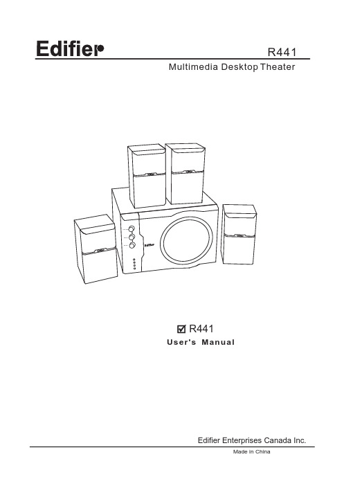
R441 Multimedia Desktop TheaterMade in ChinaEdifier Enterprises Canada Inc. User's ManualR441Welcome !Very thanks for choosing Edifier multimedia speaker,it can provide good sound for multimedia Computer and home theater. Before operating the system, please read this manual thoroughly and retain it for future reference.IMPORTANT SAFETY INFORMATIONCAUTIONThe lightning flash with arrowhead, within an equilateral triangle, is intended to alert the user to the presence of Uninsulated "dangerous voltage" within the product'sEnclosure that may be of sufficient magnitude to constitute a risk of electric shock to persons.CAUTION: TO PREVENT THE RISK OFELECTRIC SHOCK, DO NOT REMOVE COVER (OR BACK). NO USER-SERVICEABLE PARTS INSIDE. REFER SERVICING TO QUALIFIED SERVICE PERSONNEL. The exclamation point within an equilateraltriangle is intended to alert the user to the presence of important operating and maintenance (servicing) instructions in the literature accompanying the Appliance.SAFETY INSTRUCTIONSRead these instructions. Keep these instructions.Heed all warnings.Follow all instructions.Install in accordance with the manufacturer's Instructions.Do not use the speakers near water, and do notimmerse them in any liquid or pour any liquid on them.Do not block the openings in the speaker cabinets,never push objects into speaker vents or slotsbecause of fire or electric shock hazards, and provide sufficient space around the speakers for proper ventilation.The apparatus shall not be exposed to dripping or splashing and that no objects filled with liquids, such as vases, shall be placed on the apparatus.Do not install near any heat sources such as radiators,heat registers, stoves, or other apparatus (including amplifiers) that produce heat.Do not defeat the safety purpose of the polarized plug. A polarized plug has two blades with one wider than the other. The wide blade is provided for your safety . If the provided plug does not fit into your outlet, consult an electrician for replacement of the obsolete outlet.Protect the power cord from being walked on orpinched particularly at plugs, convenience receptacles, and the point where they exit from the apparatus.For added protection during lightning storms, unplug the speakers from the electrical outlet and turn of f the computer.Unplug this apparatus when unused for long periods of time.Water and moisture ----Do not use the speakers near water, and do not immerse them in any liquid or pour any liquid on them.Heat---- Place the speakers away from all heat sources.Ventilation ---- Do not block the openings in the speaker cabinets, never push objects into speaker vents or slots because of fire or electric shock hazards, and provide sufficient space around the speakers for proper ventilation.Location ---- Place the speakers in a stable location so they will not fall causing damage to the speakers or bodily harm.Cleaning ---- Unplug the speakers from the computer and from the electrical outlet before cleaning them with a damp cloth.Lightning ----For added protection during lightning storms, unplug the speakers from the electrical outlet and turn of f the computer.Servicing is required when the apparatus has been damaged in any way, such as power-supply cord orplug is damaged, liquid has been spilled or objects have fallen into the apparatus, the apparatus has beenexposed to rain or moisture, does not operate normally , or has been dropped. Refer all servicing to qualified service personnel.Please adjust the audio to proper volume to avoid damaging your health and the system.One Year Limited WarrantyEdifier warrants to the end user that all of its computer speaker systems are free from defects in material and workmanship in the course of normal and reasonable use for a term of one year from the date of purchase.This warranty is the exclusive and only warranty in effect relative to Edifier multimedia speaker systems and any otherwarranties, either expressed or implied, are invalid. Neither Edifier nor any authorized Edifier reseller is responsible for any incidental damages incurred in the use of the speakers. (This limitation of incidental or consequential damage is not applicable where prohibited.)Edifier obligation under this warranty does not apply to any defect, malfunction or failure as a result of misuse, abuse, improper installation, use with faulty or improper equipment or the use of the speaker systems with any equipment for which they were not intended.The terms of this warranty apply only to speaker systems when such speakers are returned to the respective authorized Edifier reseller where they were purchased.Under the terms of this warranty the original consumer purchaser has certain legal rights and may have other rights which vary worldwide.WARNING:TO REDUCE THE RISK OF ELECTRIC SHOCK, DO NOT EXPOSE THIS APPARATUS TO RAIN OR MOISTURE.Copyright 2005All Rights Reserved.Manual Edition 1.1, Jun 2005Printed in CHINAIntroductionOpen the packingOverviewIntroduction of back panelR441 packing list:1Sub Woofer 2Satellite Speakers 34Surround Control 5Volume Control 6Power Indicator 78User's Manual 9Line In Port 10Speaker Out 11Power Switch 12Power CordSuper Bass ControlAudio connecting cord Please check the speaker pattern marked on the package. Please contact the seller as soon as possible if you find the speaker is not the pattern you want.FRFLMDF wooden case satellite design . 6 1/2 Long-throw subwoofer driver.2-way satellite speakers. 1 PV membrane dome tweeter .3 paper coil mid-range driver.Blue power indicate.Bass, rear and main volume controllers.Magnetically shielded design.CONNECTINGSPECIFICATIONS:FIRST: CONNECTINGPlease affirm the Power Switch of the back panel that is OFF.Then Connect the satellite speakers to theoutput splints on the back panel of the Sub-woofer. Please note to match the color, golden to red and silver to black. And connect the wired controller to the wire connector.SECOND: CONNECT THE POWER SUPPLYIf you af firm your connecting is right ,then you can turn the power supply on and the system is about to wait.THIRD: TURN ONPress the FUN/POWER for a long time(about 3 seconds). The system is ready for use and all kinds of function return the sation that the system has been turned off last time ,the system automatically return the adjusting Volume. Adjusting the function, then you can enjoy the music.Total Power Output :Input Impedance:Input Sensitive:Bass Unit:M Tweeter Unit:Frequency Response:Dimension(Subwoofer):Dimension(Satellite):Gross Weight:id-range Unit:RMS 6WX4+30W 10K Ohm 450 mVAluminum coil, 4 Ohm 3Paper coil, 4 Ohm 1 42 Hz ~ 20 KHz290(W) x 193(H) x 285(D)mm 96(W) x 167(H) x 108(D)mm About 9.5 Kg6 1/2 PV membrane dome with AC power。
KENWOOD_TH-42AT说明书
KENWOOD TH-42AT 对讲机简易使用说明及说明书三种工作模式: 1,VFO模式 (频率工作模式) 2,MR模式 (信道模式) 3,CALL模式(呼叫信道,类似普通信道模式) 三种工作模式转换:分别按VFO,MR,CALL键 VFO模式 可以用键盘直接输入工作频率,也可以用频道旋钮改变工作频率。
频率步进选择:短按F键,再按T键,屏幕显示频率步进数值,用频道旋钮选择需要的步进频率。
普通模式:收发频率相同 差频工作模式:发射频率比接收频率高或低一个设定的频率 差频方向设定: 短按F键,再按REV键,屏幕显示+,表示发射频率比接收频率高设定的频率。
重复上述操作,屏幕显示“-”,表示发射频率比接收频率低设定的 频率 重复上述操作,回到普通模式。
设定频差:长按F键,再按REV键,屏幕显示频差,用频道旋钮改变频差 MR模式 如何将频率存入信道? 在VFO模式调好频率和频差,长按F键,屏幕右上脚显示频道数,用频道旋钮选择希望贮存的频道,再按MR键,频率即存入。
如何在一个频道中分别存贮发射和接收频率? 应该先存入接收频率,再存入发射频率 在VFO模式调好接收频率,长按F键,屏幕右上脚显示频道数,用频道旋钮选择希望贮存的频道,再按MR键,接收频率即存入。
在VFO模式调好发射频率,长按F键,屏幕右上脚显示频道数,用频道旋钮选择希望贮存的频道,按住PTT键不放的同时再按MR键,发射频率即存入。
CALLA模式 如何将频率存入CALL信道? 方法同存入MR信道基本相同,只是将上述的MR改为CALL即可。
亚音频: 42A已经内置标准亚音频编码功能,解码功能需安装选件 短按T键,屏幕显示T,亚音频编码功能启用 再按T键,屏幕显示CT,亚音频编解码功能启用 再按T键,亚音频功能不启用。
长按F键,再按T键,屏幕显示亚音频频率,用频道旋钮选择需要的频率 扫描: 频率扫描:长按VFO键 频道扫描:长按MR键 其它功能 改变发射功率:短按F键,再按PTT键,可以循环选择大,小,微功率(屏幕显示为H,L,EL) 照明灯长亮:短按F键,再按LAMP键 调节静噪深度:短按F键,再按SQL键,用频道旋钮调整静噪深度。
- 1、下载文档前请自行甄别文档内容的完整性,平台不提供额外的编辑、内容补充、找答案等附加服务。
- 2、"仅部分预览"的文档,不可在线预览部分如存在完整性等问题,可反馈申请退款(可完整预览的文档不适用该条件!)。
- 3、如文档侵犯您的权益,请联系客服反馈,我们会尽快为您处理(人工客服工作时间:9:00-18:30)。
建伍TM-441A简易说明
VFO~自由頻道(按下2秒頻道掃瞄)
F按2秒按VFO出現CO(載波通訊)
MR~進入記憶頻道(按下2秒記憶頻道掃瞄)
記憶方式:先選擇好頻道後按 F 調整選擇記憶組別後按MR記入,
如要修改記憶頻道先選擇好頻道後按 F 調整選擇預修改之記憶組別後按MR記入
MHZ~調頻以1MHZ調整
F+MHZ/LOCK~按鍵鎖定
A.LOCK~在LOCK模式下關閉電源後,按MHZ/LOCK 打開電源(全機鎖定)解除反向操作
F一秒+MHZ(APO)~自動關機功能
CALL~緊急呼叫鍵
F+CALL(改變緊急呼叫鍵頻道)
SHIFT~+/- 差頻(差60HZ)
F+SHIFT(AL)~優先截聽第一組記憶
REV~+/- 差頻反向
F+REV(STEP)(頻率間隔調整5/10/12.5/20/25)標準10
F 一秒+REV~按鍵音開關
LOW~功率切換(空白高/M中/L低)
F+LOW(DM)(燈光明亮調整0~4)
F 一秒+LOW(TOT)~發射時間控制
POW電源開關按鍵
F~功能鍵
VOL~音量調整
SQL~接收感度調整
TONE~音頻密碼按一次功能啟動可與加裝者通訊但不具有防干擾功能,按二次功能全部啟動(防干擾器須選購TSU7)
TONE密碼調整:F按2秒按TONE調整大旋鈕選擇內碼,任意鍵退出
F+TONE(T.ALT)~接收回鈴
*(選購)DTSS~內含音頻密碼啟動(按一次PO群呼功能啟動,按二次還原
) *(選購)DTSS/PO密碼調整:先啟動DTSS&PO後F按2秒按DTSS調整大旋鈕選擇內碼,任意鍵退出
回原廠設定1~關閉電源後,按VFO打開電源(除記憶頻道外)全部清除
回原廠設定2~關閉電源後,按MR打開電源全部清除
健伍TM-241/441操作说明
一 . 初始化(此操作需小心,会清除原机数据)
记忆频道初始化 : 关掉电源 . 按住 MR 键开机 . 松开 MR 键 . 将处理器复位 .此时主机所有功能都清零。
设定初始化 : 关掉电源 . 按住 VFO 键开机屏幕上字符全显 , 按一下VFO 键 , 此时除存储信道内容外各种设置均被复位 .
二 . 频率存储
1. 单频输入
:
按 VFO 键一次选择
频率显示方式 , 旋转频率调整大旋钮,调整至欲存储的频率 . 按 F 键 .此时屏幕上”F” 字符闪动并出现信道号码 . 旋转频率调整大旋钮,选择存储信道号 . 迅速按下 MR 键 . 在发出一声长蜂音后频率存入您选择好的频道,同时再次转入频率显示方式
,如无需调整
按 MR 键一次则转入存储信道方式并显示信道号码
,些时通过旋转频道选择大旋钮可选择已存频道。
2. 异频输入(有中继台时):
按 VFO 键选择频道显示方式 . 旋转频率调整大旋钮,调整至欲存储的频率.(如果中继带亚音则设置好亚音,按F 键2秒按TONE調整大旋鈕選擇亚音,再按TONE选择“T”或“CTCSS”模式)按 F 键一次选择 7-10 信道中的任一信道 . 按 MR 键 . 发出一声长蜂音 . 接收频率已经存入同时回到频率显示状态,继续用大钮调整发射频率,再按MR 键 2 次发出长蜂音表明发射频率已被存入。
此时屏幕上频率右边出现信道号 , 并在频率上方示— . +号,表明此频道接收发射为不同频已设定完 . 可用手咪上PTT (发射键)进行试发射检查收发频率是否不同,是否为所需差转频率。