实验20 OSPF基本配置实验(路由器—路由器)
OSPF实验配置步骤详解
OSPF试验指南目标:对于OSPF的理解达到CCNA试验考察的要求。
需要掌握的知识点:OSPF的配置。
需要掌握的命令:IOS中OSPF配置的相关命令。
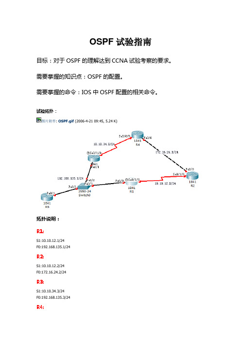
试验拓扑:图片附件: OSPF.gif (2006-4-21 09:45, 5.24 K)拓扑说明:R1:S1:10.10.12.1/24F0:192.168.135.1/24R2:S1:10.10.12.2/24F0:172.16.24.2/24R3:S1:10.10.34.3/24F0:192.168.135.3/24R4:S1:10.10.34.4/24F0:172.16.24.4/24R5:F0:192.168.135.5/24试验要求:1.路由器的IP地址如上所示。
每个路由器都有一个环回口,地址为X.X.X.X/32,X是你的路由器编号,例如: R1的环回口地址为1.1.1.1/32。
2.在所有路由器上开启OSPF路由协议。
3.配置结束后所有路由器都能看到所有网络的路由,并且能够ping通所有IP地址。
配置步骤:一.配置预配R1:Router>enable 进入特权模式Router#configure terminal 进入全局配置模式Router(config)#hostname R1 设置名字R1(config)#enable secret cisco 加密的R1(config)#no ip domain-lookup 关闭自动域名解析R1(config)#line console 0 进入线路con口R1(config-line)#password cisco 设置登陆密码R1(config-line)#login 启用密码R1(config-line)#logging synchronous 关闭同步日志R1(config-line)#exec-timeout 0 0从 con登陆永不超时(试验环境下)R1(config-line)#exitR1 (config)#line vty 0 4 telnet 远程登陆线路口R1 (config-line)#password ciscoR1 (config-line)#loginR1 (config-line)#logging synchronousR1 (config-line)#exec-timeout 0 0R1 (config-line)#exitR2:Router>enable 进入特权模式Router#configure terminal 进入全局配置模式Router(config)#hostname R1 设置名字R2(config)#enable secret cisco 加密的R2(config)#no ip domain-lookup 关闭自动域名解析R2(config)#line console 0 进入线路con口R2(config-line)#password cisco 设置登陆密码R2(config-line)#login 启用密码R2(config-line)#logging synchronous 关闭同步日志R2(config-line)#exec-timeout 0 0从 con登陆永不超时(试验环境下)R2(config-line)#exitR2 (config)#line vty 0 4 telnet 远程登陆线路口R2 (config-line)#password ciscoR2 (config-line)#loginR2 (config-line)#logging synchronousR2 (config-line)#exec-timeout 0 0R2 (config-line)#exitRouter>enable 进入特权模式Router#configure terminal 进入全局配置模式Router(config)#hostname R1 设置名字R3(config)#enable secret cisco 加密的R3(config)#no ip domain-lookup 关闭自动域名解析R3(config)#line console 0 进入线路con口R3(config-line)#password cisco 设置登陆密码R3(config-line)#login 启用密码R3(config-line)#logging synchronous 关闭同步日志R3(config-line)#exec-timeout 0 0从 con登陆永不超时(试验环境下)R3(config-line)#exitR3 (config)#line vty 0 4 telnet 远程登陆线路口R3 (config-line)#password ciscoR3 (config-line)#loginR3 (config-line)#logging synchronousR3 (config-line)#exec-timeout 0 0R3 (config-line)#exitR4:Router>enable 进入特权模式Router#configure terminal 进入全局配置模式Router(config)#hostname R1 设置名字R4(config)#enable secret cisco 加密的R4(config)#no ip domain-lookup 关闭自动域名解析R4(config)#line console 0 进入线路con口R4(config-line)#password cisco 设置登陆密码R4(config-line)#login 启用密码R4(config-line)#logging synchronous 关闭同步日志R4(config-line)#exec-timeout 0 0从 con登陆永不超时(试验环境下)R4(config-line)#exitR4 (config)#line vty 0 4 telnet 远程登陆线路口R4 (config-line)#password ciscoR4 (config-line)#loginR4 (config-line)#logging synchronousR4 (config-line)#exec-timeout 0 0R4 (config-line)#exitRouter>enable 进入特权模式Router#configure terminal 进入全局配置模式Router(config)#hostname R1 设置名字R5(config)#enable secret cisco 加密的R5(config)#no ip domain-lookup 关闭自动域名解析R5(config)#line console 0 进入线路con口R5(config-line)#password cisco 设置登陆密码R5(config-line)#login 启用密码R5(config-line)#logging synchronous 关闭同步日志R5(config-line)#exec-timeout 0 0从 con登陆永不超时(试验环境下)R5(config-line)#exitR5 (config)#line vty 0 4 telnet 远程登陆线路口R5 (config-line)#password ciscoR5 (config-line)#loginR5 (config-line)#logging synchronousR5 (config-line)#exec-timeout 0 0R5 (config-line)#exitSwitch0Switch>enable 用户模式到特权模式Switch#configure terminal 特权模式到全局配置模式Switch(config)#hostname Switch0 设置名字Switch0(config)#enable secret cisco 加密的Switch0(config)#no ip domain-lookup 关闭自动域名解析Switch0(config)#line console 0 进入线路console口Switch0(config-line)#password cisco 设置登陆密码Switch0(config-line)#login 启用密码Switch0(config-line)#logging synchronous 关闭同步日志Switch0(config-line)#exec-timeout 0 0 从 console登陆永不超时(试验环境下)Switch0(config-line)#exit 退出Switch0(config)#line vty 0 4 telnet 远程登陆线路口Switch0(config-line)#password ciscoSwitch0(config-line)#loginSwitch0(config-line)#logging synchronousSwitch0(config-line)#exec-timeout 0 0Switch0(config-line)#exit二、配置各接口IP地址R1:R1(config)#interface fastEthernet 0/0 以太网接口R1(config-if)#ip address 192.168.135.1 255.255.255.0 R1(config-if)#no shutdownR1(config-if)#exitR1(config)#interface serial 0/1/0 串行接口R1(config-if)#ip address 10.10.12.1 255.255.255.0R1(config-if)#clock rate 64000R1(config-if)#no shutdownR1(config-if)#exitR1(config)#interface loopback 0R1(config-if)#ip address 1.1.1.1 255.255.255.255R1(config-if)#no shutdownR1(config-if)#exitR2:R2(config)#interface serial 0/1/0R2(config-if)#ip address 10.10.12.2 255.255.255.0R2(config-if)#no shutdownR1(config-if)#clock rate 64000R2(config)#interface fastEthernet 0/0R2(config-if)#ip address 172.16.24.2 255.255.255.0 R2(config-if)#no shutdownR2(config)#interface loopback 0R2(config-if)#ip address 2.2.2.2 255.255.255.255R2(config-if)#no shutdownR3:R3(config)#interface serial 0/1/0R3(config-if)#ip address 10.10.34.3 255.255.255.0R3(config-if)#no shutdownR1(config-if)#clock rate 64000R3(config)#interface fastEthernet 0/1R3(config-if)#ip address 192.168.135.3 255.255.255.0 R3(config-if)#no shutdownR3(config)#interface loopback 0R3(config-if)#ip address 3.3.3.3 255.255.255.255R3(config-if)#no shutdownR4:R4(config)#interface serial 0/0/0R4(config-if)#ip address 10.10.34.4 255.255.255.0R4(config-if)#no shutdownR1(config-if)#clock rate 64000R4(config)#interface fastEthernet 0/0R4(config-if)#ip address 172.16.24.4 255.255.255.0 R4(config-if)#no shutdownR4(config)#interface loopback 0R4(config-if)#ip address 4.4.4.4 255.255.255.255R4(config-if)#no shutdownR5(config)#interface fastEthernet 0/1R5(config-if)#ip address 192.168.135.5 255.255.255.0 R5(config-if)#no shutdownR5(config)#interface loopback 0R5(config-if)#ip address 5.5.5.5 255.255.255.255R5(config-if)#no shutdown三、配置OSPF协议R1:R1(config)#router ospf 1R1(config-router)#network 10.10.12.1 0.0.0.0 area 0R1(config-router)#network 192.168.135.1 0.0.0.0 area 0 R1(config-router)#network 1.1.1.1 0.0.0.0 area 0R2:R2(config)#router ospf 2R2(config-router)#network 10.10.12.2 0.0.0.0 area 0R2(config-router)#network 172.16.24.2 0.0.0.0 area 0 R2(config-router)#network 2.2.2.2 0.0.0.0 area 0R3:R3(config)#router ospf 3R3(config-router)#network 10.10.34.3 0.0.0.0 area 0R3(config-router)#network 192.168.135.3 0.0.0.0 area 0 R3(config-router)#network 3.3.3.3 0.0.0.0 area 0R4(config)#router ospf 4R4(config-router)#network 10.10.34.4 0.0.0.0 area 0R4(config-router)#network 172.16.24.4 0.0.0.0 area 0 R4(config-router)#network 4.4.4.4 0.0.0.0 area 0R5:R5(config)#router ospf 5R5(config-router)#network 192.168.135.5 0.0.0.0 area 0 R5(config-router)#network 5.5.5.5 0.0.0.0 area 0四、查看配置。
实验二 OSPF基本配置
实验报告一,实验目标:
1,配置单区域的OSPF协议;
2,配置多区域的OSPF协议;
3,掌握OSPF协议Router ID的选取原理。
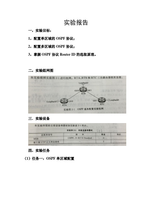
二,实验组网图
三.实验设备
四,实验任务
(1)任务一:OSPF单区域配置
(2)任务二:OSPF多区域配置
(3)任务三:Router ID 的选取
五,思考题:在单区域和多区域的配置下,RTB的LSDB有无区别?
答:在单区域配置下,RTB只有Area 0的LSDB,而在多区域下,RTB既有Area 0的LSDB,也有Area 1的LSDB,这就是ABR 的特性和作用。
六,实验总结
在这次实验中,实验一是OSPF的单区域配置,在启动OSPF 时,把接口地址使能,就是在一个区域中把接口地址的网段发布(实验一是在区域Area 0中);
实验二则是OSPF的多区域配置,也是在启动OSPF时,把接口地址使能,但是是在不同区域中,这样有骨干和非骨干区域,有点事可以减少区域内的LSA的数量,便于管理,减少路由震荡的影响。
实验三则是查看Router ID,Router ID未配置时时自己选择,由于本实验自己配置,所以和预想的结果有点不一样,当删除
Loopback 0时,Router ID应该时2.2.2.2,但是变为20.0.0.1。
路由器的基本配置以及路由协议

路由器的基本配置以及路由协议实验目的:(1)熟悉路由器(2)了解路由器的配置方式(3)掌握路由器的基本配置命令(4)熟悉路由器的路由配置(5)掌握RIP协议的基本配置(6)了解OSPF协议的基本配置实验步骤:路由器各接口IP地址设置如下:RTA RTBE0/0 192.168.2.1 192.168.3.1S3/0 192.168.7.1 192.168.7.2 PC机IP地址和缺省网关的IP地址如下:IP地址缺省网关地址PC21 192.168.2.2 192.168.2.1 24 PC19 192.168.2.3 192.168.2.1 24 PC20 192.168.2.4 192.168.2.1 24 PC18 192.168.3.5 192.168.3.1 24 PC17 192.168.3.6 192.168.3.1 24 PC16 192.168.3.7 192.168.3.1 24静态路由配置[Quiday]sysname RTA[RTA]int e0/0[RTA-e0/0]ip address 192.168.2.1 24[RTA-e0/0]int s3/0RTBRTAE0/0: 192.168.2.1/24S3/0: 192.681.7.2/24S3/0: 192.168.7.1/24E0/0: 192.168.3.1/24[RTA-s3/0]ip address 192.168.7.1[RTA-s3/0]q[RTA]ip rout-static 192.168.3.1 24 192.168.7.2 preference 60运行ping 192.168.3.6 24 ping 通RIP协议配置[RTA]undo ip ro 192.168.3.1 24 192.168.7.2[RTA]rip[RTA-rip]network 192.168.2.1[RTA-rip]network 192.168.7.1运行ping 192.168.3.6 24 ping 通RTB也如上述操作进行实验总结:静态路由原理:配置静态路由可以人为的指定对某网络段访问时要经过的路径,手动添加每一个能到达的网络号和接口,在网络结构比较简单且一般到达某一网络所经过的路径唯一的情况下才采用静态路由,不是使用动态路由协议来生成路由表的,以跳数为标准选择最佳网络路径,不适合复杂网络使用RIP:RIP有RIP-1和RIP-2两个版本,两者的路由算法都相同,RIP-2支持明文认证和MD5密文认证,并支持变长子网掩码,选择域路由,外部路由标记,子网掩码,下一跳地址以及验证机制。
基本OSPF配置实验

基本OSPF配置实验基本OSPF 配置实验在路由器R1 上配置OSPFR1(config)#router ospf 1R1(config-router)#R1(config-router)#network 172.16.1.16 0.0.0.15 area 0 R1(config-router)#network 192.168.10.0 0.0.0.3 area 0 R1(config-router)#network 192.168.10.4 0.0.0.3 area 0 R1(config-router)#endR2(config)#router ospf 1R2(config-router)#R2(config-router)#network 10.10.10.0 0.0.0.255 area 0 R2(config-router)#network 192.168.10.0 0.0.0.3R2(config-router)#network 192.168.10.8 0.0.0.3 area 0 R2(config-router)#endR3(config)#router ospf 1R3(config-router)#network 172.16.1.32 0.0.0.7 area 0 R3(config-router)#network 192.168.10.4 0.0.0.3 area 0 R3(config-router)#network 192.168.10.8 0.0.0.3 area 0 R3(config-router)#endR1(config)#interface loopback 0R1(config-if)#ip address 10.1.1.1 255.255.255.255R2(config)#interface loopback 0R2(config-if)#ip address 10.2.2.2 255.255.255.255R3(config)#interface loopback 0R3(config-if)#ip address 10.3.3.3 255.255.255.255R1(config)#router ospf 1R1(config-router)#router-id 10.4.4.4R1#(config-router)#endR1#clear ip ospf processReset ALL OSPF processes?[no]:yes使用router-id 命令的no 形式删除所配置的路由器ID。
计算机网络OSPF路由配置实验

一、实验环境1.使用模拟器GNS3构建如下网络拓扑图(图1):(图1)二、实验步骤1. 步骤一:配置路由表R1:R1#conf tEnter configuration commands, one per line. End with CNTL/Z.R1(config)#int lo0R1(config-if)#ip addressR1(config-if)#ip address 1.1.1.1 255.255.255.0R1(config-if)#int f0/0R1(config-if)#ip address 1.27.12.1 255.255.255.0R1(config-if)#no shutR2:R2#conf tEnter configuration commands, one per line. End with CNTL/Z.R2(config)#int lo0R2(config-if)#*Mar 1 00:21:43.387: %LINEPROTO-5-UPDOWN: Line protocol on Interface Loopback0, changed state to upR2(config-if)#ip address 2.2.2.2 255.255.255.0R2(config-if)#int f0/0N1 - OSPF NSSA external type 1, N2 - OSPF NSSA external type 2E1 - OSPF external type 1, E2 - OSPF external type 2i - IS-IS, su - IS-IS summary, L1 - IS-IS level-1, L2 - IS-IS level-2ia - IS-IS inter area, * - candidate default, U - per-user static routeo - ODR, P - periodic downloaded static routeGateway of last resort is not set1.0.0.0/8 is variably subnetted, 3 subnets, 2 masksO 1.1.1.1/32 [110/21] via 1.27.11.2, 00:16:38, FastEthernet0/1C 1.27.11.0/24 is directly connected, FastEthernet0/1O 1.27.12.0/24 [110/20] via 1.27.11.2, 00:16:38, FastEthernet0/12.0.0.0/32 is subnetted, 1 subnetsO 2.2.2.2 [110/11] via 1.27.11.2, 00:16:38, FastEthernet0/13.0.0.0/24 is subnetted, 1 subnetsC 3.3.3.0 is directly connected, Loopback04.抓取OSPF包,在R1和R2之间的链路上5.抓包结果:成功抓到arp协议的请求和应答三、实验总结经过这次实验,我个人得到了不少的收获,一方面加深了我对课本理论的认识,另一方面也提。
实验 OSPF路由协议的配置与应用

OSPF路由协议的配置与应用一、实验目的1.理解三层交换机的工作原理;2.理解OSPF路由协议的工作原理;3. 掌握虚拟局域网VLAN的设置;4.掌握OSPF路由协议的配置方法。
二、实验内容1. 根据网络拓扑图,组建网络;2. 配置VLAN、设备互联地址、模拟终端IP地址;3. 配置OSPF路由协议,计算动态路由表;4. 测试网络互联互通。
三、实验步骤1、根据网络拓扑图,组建网络。
如图所示,其中路由器Router1和Router3之间使用V.35 DTE/DCE线缆进行连接,三层交换机Switch中端口Ethernet1/0/1~Ethernet1/0/2属于VLAN 20,而端口Ethernet 1/0/24属于VLAN 10。
2.三层交换机Switch的配置#进入系统视图<Switch >system-view#创建VLAN 10,并配置接口IP地址[Switch]vlan 10[Switch-vlan10] interface vlan-interface 10[Switch -Vlan-interface10]ip address 192.168.111.2 255.255.255.252#将端口Ethernet 1/0/24加入到VLAN 10中[Switch -Vlan-interface10]vlan 10[Switch-vlan10]port Ethernet 1/0/24#创建VLAN 20,并配置接口IP地址[Switch -Vlan-interface10]vlan 20[Switch-vlan20]interface vlan-interface 20[Switch –Vlan-interface20]ip address 192.168.112.1 255.255.255.0 #将端口Ethernet 1/0/1~1/0/2加入到VLAN 20中[Switch –Vlan-interface20]vlan 20[Switch-vlan20] port Ethernet 1/0/1 to Ethernet 1/0/2#退出VLAN视图,进入系统视图[Switch-vlan20]quit#配置交换机Router-ID[Switch]router id 1.1.1.1#创建OSPF进程并进入OSPF视图[Switch]ospf#在OSPF视图下创建区域0并进入区域视图[Switch-ospf-1]area 0#指定属于该区域的接口网段[Switch-ospf-1]network 192.168.111.0 0.0.0.3[Switch-ospf-1]network 192.168.112.0 0.0.0.2553.路由器Router1的配置#进入系统视图<Router1>system-view#配置端口Ethernet 0/1的IP地址[Router1]interface ethernet 0/1[Router1-Ethernet0/1]ip address 192.168.111.1 255.255.255.252#配置端口Serial 1/0的IP地址[Router1-Ethernet0/1]interface serial 1/0[Router1-Serial1/0]ip address 202.1.1.1 255.255.255.252#配置路由器Router-ID[Router1-Serial1/0]quit[Router1]router id 2.2.2.2#创建OSPF进程并进入OSPF视图[Router1]ospf#在OSPF视图下创建区域0并进入区域视图[Router1-ospf-1]area 0#指定属于该区域的接口网段[Router1-ospf-1-area-0.0.0.0]network 192.168.111.0 0.0.0.3[Router1-ospf-1-area-0.0.0.0]network 202.1.1.0 0.0.0.34.路由器Router2的配置#进入系统视图<Router2>system-view#配置以太网接口0/1的IP地址[Router2]interface loopback 0[Router2-Loopback0]ip address 192.168.113.1 255.255.255.255#配置端口Serial 1/0的IP地址[Router2]interface serial 1/0[Router2-Serial1/0]ip address 202.1.1.2 255.255.255.252#配置路由器Router-ID[Router2-Serial1/0]quit[Router2]router id 3.3.3.3#创建OSPF进程并进入OSPF视图[Router2]ospf#在OSPF视图下创建区域0并进入区域视图[Router2-ospf-1]area 0#指定属于该区域的接口网段[Router2- ospf-1-area-0.0.0.0]network 202.1.1.0 0.0.0.3 [Router2- ospf-1-area-0.0.0.0]network 192.168.113.0 05.实验结果验证1) 查看三层交换机Switch的路由表[Switch] display ip routing-tableRouting Tables: PublicDestinations :8 Routes : 82) 查看路由器Router1的路由表[Router1] display ip routing-tableRouting Tables: PublicDestinations : 9 Routes : 93) 查看路由器Router2的路由表[Router2] display ip routing-tableRouting Tables: PublicDestinations : 9 Routes : 94) 在PC1的“命令提示符”下输入ping 192.168.103.2,结果如图4-15所示;反之,从PC3同样可以ping通PC1和PC2。
基本任务9 OSPF 基本配置

实训_9_: OSPF配置实训学时:4实训类型:(综合、设计、验证)一、实训内容0SPF配置。
二、实训目的1、在路由器上启动OSPF 路由进程2、启用参与路由协议的接口,并且通告网络及所在的区域三、组织形式采用分组形式,教师指导四、实训条件计算机、Dynamips 路由模拟器。
五、实训步骤(1)步骤1:配置路由器R1R1(config)#router ospf 1R1(config-router)#router-id 1.1.1.1R1(config-router)#network 1.1.1.0 255.255.255.0 area 0R1(config-router)#network 192.168.12.0 255.255.255.0 area 0 (2)步骤2:配置路由器R2R2(config)#router ospf 1R2(config-router)#router-id 2.2.2.2R2(config-router)#network 192.168.12.0 255.255.255.0 area 0R2(config-router)#network 192.168.23.0 255.255.255.0 area 0R2(config-router)#network 2.2.2.0 255.255.255.0 area 0(3)步骤3:配置路由器R3R3(config)#router ospf 1R3(config-router)#router-id 3.3.3.3R3(config-router)#network 192.168.23.0 255.255.255.0 area 0R3(config-router)#network 192.168.34.0 255.255.255.0 area 0R3(config-router)#network 3.3.3.0 255.255.255.0 area 0(4)步骤4:配置路由器R4R4(config)#router ospf 1R4(config-router)#router-id 4.4.4.4R4(config-router)#network 4.4.4.0 0.0.0.255 area 0R4(config-router)#network 192.168.34.0 0.0.0.255 area 0【技术要点】(1)OSPF 路由进程ID 的范围必须在1-65535 之间,而且只有本地含义,不同路由器的路由进程ID 可以不同。
实训四:OSPF路由协议配置.
配置过程
• 路由器R3 • 二、配置OSPF路由协议 • Router ospf 1 • network 192.168.4.0 0.0.0.255 area 0 • network 192.168.2.0 0.0.0.255 area 0
验证配置的正确性
• 要对配置的正确性进行验证,最好的方法 就是使用
实训 OSPF路由协议配置
实训目的
• 1、掌握路由器的OSPF单域配置 • 2、掌握三层交换机的OSPF单域配置
创建OSPF进程
• 创建一个OSPF路由进程
– Router(config)#router ospf 100
• 定义关联的IP地址范围
– Router(config-router)#network 192.168.0.0 0.0.255.255 area 0
配置过程
• 路由器R2 • 二、配置OSPF路由协议 • Router ospf 1 • network 192.168.3.0 0.0.0.255 area 0 • network 192.168.2.0 0.0.0.255 area 0
配置过程
• 路由器R3 • 一、配置接口的相关参数 • En • Config ter • Int f 0/0 • ip add 192.168.4.1 255.255.255.0 • no shutdown • Int f 0/1 • ip add 192.168.2.3 255.255.255.0 • no shutdown
实例
F0/1:192.168.2.1 F0/0:192.168.1.1 R1
F0/1:192.168.2.2 F0/0:192.168.3.1
R2
F0/1:192.168.2.3 R3
- 1、下载文档前请自行甄别文档内容的完整性,平台不提供额外的编辑、内容补充、找答案等附加服务。
- 2、"仅部分预览"的文档,不可在线预览部分如存在完整性等问题,可反馈申请退款(可完整预览的文档不适用该条件!)。
- 3、如文档侵犯您的权益,请联系客服反馈,我们会尽快为您处理(人工客服工作时间:9:00-18:30)。
实验二十一:OSPF 基本配置实验
一、实验介绍:
1、实验名称:OSPF 基本配置实验
2、实验目的:R2624路由器OSPF 基本配置技术
3、实验设备:R2624路由器、V35DCE 、V35DTE
4、实验时间:10分钟
二、实验拓扑:
PC1 PC2
三、实验配置:
R1配置:(DCE )
R1 (config)# hostname R1 R1(config)# interface F0
R1(config-if)# ip address 192.168.10.1 255.255.255.0 R1(config-if)# no shut R1(config-if)# exit
R1(config)# interface Serial2
R1(config-if)# encapsulation ppp !封装接口协议为PPP R1(config-if)# ip address 172.16.1.1 255.255.255.0
R1(config-if)# clock rate 64000 !定义时钟频率为64000(在DCE 端设置) R1(config-if)# no shut R1(config-if)# exit
R1(config)# router ospf 1
R1(config-router)# network 172.16.1.0 0.0.0.255 area 0 R1(config-router)# network 192.168.10.0 0.0.0.255 area 0 R1(config-router)# exit
R2配置:(DTE )
R1(DCE )
R2(DTE )
IP 192.168.10.2/24 网关 192.168.10.1
IP 192.168.20.2/24 网关 192.168.20.1
R2(config)# hostname R2
R2(config)# interface F0
R2(config-if)# ip address 192.168.20.1 255.255.255.0
R2(config-if)# no shut
R2(config-if)# exit
R2(config)# interface Serial0
R2(config-if)# encapsulation ppp !封装接口协议为PPP
R2(config-if)# ip address 172.16.1.2 255.255.255.0
R2(config-if)# no shut
R2(config-if)# exit
R2(config)# router ospf 1
R2(config-router)# network 172.16.1.0 0.0.0.255 area 0 R2(config-router)# network 192.168.20.0 0.0.0.255 area 0 R2(config-router)# exit
四、验证命令
Show ip ospf
Show ip ospf interface
Show ip ospf neighbor
Show ip route
Show running-config。