美国Parker-PDF Z8、E4、PZ、EU、PP型汽缸密封圈
Parker PCO2系列气缸保护器用户指南说明书
aerospaceclimate control electromechanical filtrationfluid & gas handling hydraulics pneumatics process control sealing & shielding1Safety Information (1)1.1Markings and Symbols (1)2Description (2)2.1Stages of Purification (2)2.2Technical Specification (2)2.2.1Pressure Correction Factors (2)2.3Weights and Dimensions (3)2.4Receiving and Inspecting the Equipment (4)2.4.1Storage (4)2.4.2Unpacking (4)2.4.3Overview of the Equipment (5)3Installation & Commissioning (6)3.1Recommended system layout (6)3.2Locating the Equipment (7)3.2.1Space Requirements (7)3.3Mechanical Installation (7)3.3.1General Requirements (7)3.3.2Securing the Unit (7)4Operating the Equipment (8)4.1Starting the Equipment (8)5Servicing (9)5.1Cleaning (9)5.2Service Intervals (9)5.3Preventative Maintenance Kits (10)5.4Maintenance Procedures (11)5.4.1Cartridge Replacement Procedure (PCO2-400 Models Only) (11)5.4.2OIL-X Element Change Procedure (13)5.4.3Cartridge Replacement Procedure (PCO2-800 to PCO2-4800 Models) (14)5.4.4IP50 Element Change Procedure (16)6Troubleshooting (17)1 Safety InformationDo not operate this equipment until the safety information and instructions in this user guide have been read and understood by all personnel concerned.USER RESPONSIBILITYFAILURE OR IMPROPER SELECTION OR IMPROPER USE OF THE PRODUCTS DESCRIBED HEREIN OR RELATED ITEMS CAN CAUSE DEATH, PERSONAL INJURY AND PROPERTY DAMAGE.This document and other information from Parker Hannifin Corporation, its subsidiaries and authorised distributors provide product or system options for further investigation by users having technical expertise.The user, through its own analysis and testing, is solely responsible for making the final selection of the system and components and assuring that all performance, endurance, maintenance, safety and warning requirements of the application are met. The user must analyse all aspects of the application, follow applicable industry standards, and follow the information concerning the product in the current product catalogue and in any other materials provided from Parker or its subsidiaries or authorised distributors.To the extent that Parker or its subsidiaries or authorised distributors provide component or system options based upon data or specifications provided by the user, the user is responsible for determining that such data and specifications are suitable and sufficient for all applications and reasonably foreseeable uses of the components or systems.Only competent personnel trained, qualified, and approved by Parker Hannifin should perform installation, commissioning, service and repair procedures.With the exception of oxygen, any gas can cause asphyxiation in high enough concentrations. Always ensure that the unit is operated in a well ventilated area and all of the vent ports on the rear of the unit are kept clear and free from blockages.Use of the equipment in a manner not specified within this user guide may result in an unplanned release of pressure, which may cause serious personal injury or damage.When handling, installing or operating this equipment, personnel must employ safe engineering practices and observe all related regulations, health & safety procedures, and legal requirements for safety.Ensure that the equipment is depressurised prior to carrying out any of the scheduled maintenance instructions specified within this user guide. Parker Hannifin can not anticipate every possible circumstance which may represent a potential hazard. The warnings in this manual cover the most known potential hazards, but by definition can not be all-inclusive. If the user employs an operating procedure, item of equipment or a method of working which is not specifically recommended by Parker Hannifin the user must ensure that the equipment will not be damaged or become hazardous to persons or property.Most accidents that occur during the operation and maintenance of machinery are the result of failure to observe basic safety rules and procedures. Accidents can be avoided by recognising that any machinery is potentially hazardous.Should you require an extended warranty, tailored service contracts or training on this equipment, or any other equipment within the Parker Hannifin range, please contact your local Parker Hannifin office.Details of your nearest Parker Hannifin sales office can be found at /gsfeRetain this user guide for future reference.Related Documents:• Preventative Maintenance Guide 176070002• 12 Month Service Instructions 1760700031.1 Markings and SymbolsThe following markings and international symbols are used on the equipment or within this manual:2 DescriptionThe Parker domnick hunter PCO2 systems offer a comprehensive solution to preserve and guarantee the quality of gaseous carbon dioxide used in sparkling beverage bottling.Operating as a Quality Incident Protection system against potential carbon dioxide impurities, the system guarantees the gas quality so itremains within industry and company guidelines, preventing detrimental consequences to the finished end beverage, producers reputation and their bottom-line.PCO2 is the beverage industry preferred choice and is installed in over 150 countries worldwide.2.1 Stages of Purification* Optional - Sterilising Grade: consult Parker for operational use.2.2 Technical SpecificationThis specification is valid when the equipment is located, installed, operated, and maintained as specified within this user guide.Stated flow rates are at 24.1 bar g (350 psi g).*Systems are installed in duplex / parallel to double the flow rate.All systems are supplied as NPT with stainless steel adapters 'NPT to BSP' as standard.PCO2 CO 2 systems are for gaseous CO 2 only.For flows at other pressures, apply the correction factors shown below.2.2.1 Pressure Correction FactorsStage 10.01 micron particle filtrationRemoval of non-volatile organic residue (NVOR) and other contaminants down to 0.01 ppmStage 2Removal of water vapour and partial removal of hydrocarbonsStage 3Primary removal of aromatic hydrocarbons (Benzene, Toulene etc and Acetaldehyde)Stage 4Removal of sulphur compounds (COS, H2S, DMS etc)Stage 50.01 micron particle filtrationStage 6*Point of use VBACE sterile gas membrane. Hi Flow Tetpor II ParameterUnitsPCO2400PCO2800PCO21600PCO22400PCO23200PCO24000PCO24800PCO23200(Duplex)*PCO24000(Duplex)*PCO24800(Duplex)*Technical DataMinimum Operating Pressure bar g (psi g) 3.0(43.5) 3.0(43.5) 3.0(43.5) 3.0(43.5) 3.0(43.5) 3.0(43.5) 3.0(43.5) 3.0(43.5) 3.0(43.5) 3.0(43.5)Maximum Operating Pressure bar g (psi g)20.7(300)24.1(350)24.1(350)24.1(350)24.1(350)24.1(350)24.1(350)24.1(350)24.1(350)24.1(350)Minimum Operating Temperature ºC (ºF)-20(-4)-20(-4)-20(-4)-20(-4)-20(-4)-20(-4)-20(-4)-20(-4)-20(-4)-20(-4)Maximum Operating Temperature ºC (ºF)40(104)40(104)40(104)40(104)40(104)40(104)40(104)40(104)40(104)40(104)Inlet CO 2 Quality ISBT beverage grade CO 2FlowrateKg / hr 1813637261089145118142177290336284354Lb / hr40080016002400320040004800640080009600Port Connections CO 2 Inlet in 1” NPT 1-1/2" NPT CO 2 Outletin1” NPT1-1/2" NPTInlet Pressurebar g 345678*********psi g44587387102116130145160174189Correction Factor 0.190.230.280.330.380.420.470.520.570.610.66Inlet Pressurebar g 1415161718192021222324psi g203218232247261275290304319333350Correction Factor0.710.760.800.850.900.95111112.3 Weights and Dimensions*Clearance required for the removal and servicing of the cartridges.Model Height (H)Width (W)Depth (D)(a)(b)(c)Clearance*Weight mm ins mm ins mm ins mm ins mm ins mm ins mm ins kg Ibs PCO2-400103540.7556422.2035013.78189.57.534013.430011.8168026.875165PCO2-800106141.7763224.8845017.72215.58.534013.440015.7568026.884185PCO2-1600106141.7780131.5445017.72215.58.550920.0440015.7568026.8128282PCO2-2400106141.7797038.1945017.72215.58.567826.7040015.7568026.8172379PCO2-3200106141.77113944.8445017.72215.58.584733.3540015.7568026.8217478PCO2-4000106141.77130851.5045017.72215.58.5101640.040015.7568026.8260573PCO2-4800106141.77147758.1545017.72215.58.5118546.740015.7568026.8304670(b)(b)PCO2-400PCO2-800 to PCO2-48002.4 Receiving and Inspecting the EquipmentOn receipt of the equipment carefully inspect the packaging for damage. If the packaging is damaged inform the delivery company immediately and contact your local Parker Hannifin office.2.4.1 StorageIf the equipment is to be stored prior to installation, do not remove it from the packaging. Ensure that it is stored in an upright position as indicated by the arrows on the packaging.Do not attempt to lift the equipment by yourself. It is recommended that the equipment be carried by a minimum of two persons ortransported on a pallet truck.Note. The storage area should be secure and the environmental conditions should fall within those specified in the technical specification.If the equipment is stored in an area where the environmental conditions fall outside of those specified, it is essential that it be moved to its final location (installation site) and left to stabilise prior to unpacking. Failure to do this could cause condensing humidity and potential failure of the equipment.2.4.2 UnpackingRemove the lid and all four sides of the packing crate. Carefully move the unit to its final location using a forklift truck or pallet truck. Once in it’s final location, remove the unit from the pallet via the 4x bolts.Note: Suitable slings and an overhead crane maybe required depending on the product size.2.4.3 Overview of the EquipmentKey:Item Description1System Inlet2System Outlet3AA020P OIL-X Filter (PCO2-400 Models only) IP50-AA-0465GPCO2 Filter4Manual Filter Drain5Manifold Lifting Handle6Manifold Hinge (PCO2-800 to PCO2-4800 Models) 7Desiccant Cartridge8PCO2 Column9Pressure Gauge10Lifting Eye Bolt7 8PCO2-400PCO2-800 to PCO2-4800 73 Installation & Commissioning3.1 Recommended system layoutOnly competent personnel trained, qualified, and approved by Parker Hannifin should perform commissioning and service procedures.1Liquid CO2 storage tank 2Vaporiser3Stainless steel piping4Pre filtration - Stage One 5PCO2 Unit6Post filtration - Stage five 7Isolation valves8Sterile Filter (Optional)54678 2313.2 Locating the Equipment3.2.1 Space RequirementsThe equipment should be mounted on a flat surface capable of supporting its own weight plus the weight of all ancillary parts. The minimum footprint requirements are specified below, however there must be adequate space around the equipment to allow airflow and access for maintenance purposes and lifting equipment. A minimum spacing of approximately 500mm (20 ins) is recommended around all sides of the unit and 750mm (30 ins) above it.Do Not position the equipment so that it is difficult to operate.3.3 Mechanical Installation3.3.1 General RequirementsEnsure that all piping materials are suitably rated for the application, clean and debris free. The diameter of the pipes must be sufficient to allow unrestricted inlet air supply to the equipment.Apply approximately 8 - 12 turns of P .T.F.E tape to the high quality stainless steel piping.Fit the piping along with the relevant pre and post filtration onto the inlet and outlet. Isolation valves must be installed before the inlet filtration and after the outlet filtration.When routing pipes ensure that they are adequately supported to prevent damage or leaks in the system.All components used within the system must be rated to at least the maximum operating pressure of the equipment. It is recommended that the system is protected with suitably rated pressure relief valves.3.3.2 Securing the UnitMounting holes are provided in the feet of the unit. Once the unit has been positioned in its final location ensure that it is securely fixed in place.500mm (20ins)(20ins)500mm(20ins)4 Operating the Equipment4.1 Starting the EquipmentNote: On start-Up it is normal for the outlet temperature to increase for a limited period of time.1 Open the inlet valve slowly to gradually pressurise the PCO2 unit.2 Open the outlet valve slowly to re-pressurise the downstream piping.Do not open the inlet or outlet valves rapidly or subject the PCO2 unit to excessive pressure differential as damage may occur.5 Servicing5.1 CleaningClean the equipment with a damp cloth only. If required you may use a mild detergent, however do not use abrasives or solvents as they may damage the warning labels on the equipment.5.2 Service IntervalsParker recommend that the adsorbent cartridges and filter elements are exchanged within the recommended 12-month period or before the recorded cumulative mass of the unit has been exceeded or after a quality incident has occurred, whichever comes first. Please refer to the below table for the maximum mass flow of each model.Service12 M o n t h s24 M o n t h s36 M o n t h s48 M o n t h s60 M o n t h s72 M o n t h sAPCO2 Model Number Max Operating Pressure Bar/PSI Flow kg/hr @ Max OperatingPressureMax Mass over 12 Months:kgFlow lb/hr@ Max OperatingPressureMax Mass over 12 Months:IbMax Mass over 12 Months: Tonne (Metric Ton)PCO2-40020 Barg / 300 PSIG 181158121640034944001581PCO2-80024 Barg / 350 PSIG 363317116880069888003170PCO2-160024 Barg / 350 PSIG 72663423361600139776006340PCO2-240024 Barg / 350 PSIG 108995135042400209664009510PCO2-320024 Barg / 350 PSIG 14511267593632002795520012680PCO2-400024 Barg / 350 PSIG 18141584710440003494400015850PCO2-480024 Barg / 350 PSIG 21771901827248004193280019020PCO2-3200 (Duplex)24 Barg / 350 PSIG 29032536060864005591040025361PCO2-4000 (Duplex)24 Barg / 350 PSIG 36283169420880006988800031701PCO2-4800 (Duplex)24 Barg / 350 PSIG435438036544960083865600380415.3 Preventative Maintenance KitsRequired every 8000Hrs (12 months)PCO2-400PCO2-800 to PCO2-4800AAAModelPM Kit NumberKit ContentsOrder QuantityPCO2 400MK-PCO2-4001x Desiccant cartridges 2x Outlet block o-rings 2x P020AA Filter element 2x Filter bowl o-rings 1PCO2 800MK-PCO2-8002x Desiccant cartridges 2x Outlet block o-rings 2x IP50-AA Filter element 2x Filter bowl o-rings 1PCO2 1600MK-PCO2-16004x Desiccant cartridges 2x Outlet block o-rings 2x IP50-AA Filter element 2x Filter bowl o-rings 1PCO2 2400MK-PCO2-24006x Desiccant cartridges 2x Outlet block o-rings 2x IP50-AA Filter element 2x Filter bowl o-rings 1PCO2 3200MK-PCO2-32008x Desiccant cartridges 2x Outlet block o-rings 2x IP50-AA Filter element 2x Filter bowl o-rings 1PCO2 4000MK-PCO2-400010x Desiccant cartridges 2x Outlet block o-rings 2x IP50-AA Filter element 2x Filter bowl o-rings 1PCO2 4800MK-PCO2-480012x Desiccant cartridges 2x Outlet block o-rings 2x IP50-AA Filter element 2x Filter bowl o-rings 1PCO2 3200 (Duplex)MK-PCO2-640016x Desiccant cartridges 4x Outlet block o-rings 4x IP50-AA Filter element 4x Filter bowl o-rings 1PCO2 4000 (Duplex)MK-PCO2-800020x Desiccant cartridges 4x Outlet block o-rings 4x IP50-AA Filter element 4x Filter bowl o-rings 1PCO2 4800 (Duplex)MK-PCO2-960024x Desiccant cartridges 4x Outlet block o-rings 4x IP50-AA Filter element 4x Filter bowl o-rings1With OIL-X IP50 filter elements (PCO2-800 to PCO2-4800)With OIL-X filter elements (PCO2-400 Models only)5.4 Maintenance Procedures5.4.1 Cartridge Replacement Procedure (PCO2-400 Models Only)Ensure that the system is fully depressurised before carrying out the below maintenance procedures.A Remove the M12 nuts from one side of the manifold.B Using the handle, carefully lift and remove the manifold from the unit and store in a safe place.Ensure that the inlet and outlet piping is adequately supported before removing the manifold from the unit.C Remove the old desiccant cartridges and dispose in accordance with local regulations.D Remove the o-ring from the outlet manifold block and replace with the one provided within the 12 month Preventative Maintenance kits.Note: Apply a light coating of Molykote III grease to the o-rings.E Insert the replacement desiccant cartridges into the columns.F Refit the manifold and secure the M12 nuts in sequence, starting with the centre nuts and working outwards. The nuts should be secured intwo stages. Stage 1: 27Nm (20 ft.lb) and Stage 2: 40Nm (30 ft.lb).A5.4.2 OIL-X Element Change ProcedureA Ensure that the filters are fully depressurised by opening the manual drain.B Unscrew the filter bowl and remove the used element.C Replace the o-ring located on the filter bowl with the new one provided within the 12month Preventative Maintenance kits.D Insert the new element into the filter bowl ensuring that the lugs are correctly seated inthe grooves.E Refit the filter bowl to the head ensuring that the threads are fully engaged and thelocking details are aligned.F Close the manual drain and re-pressurise the system.We recommend the use of gloves when touching contaminated elements.Ensure to lubricate the o-ring and threads with Molykote III grease.Item Description Item Description1Filter head4Filter bowl o-ring2Filter bowl5Manual Drain3Element5.4.3 Cartridge Replacement Procedure (PCO2-800 to PCO2-4800 Models)The top manifold has been split into two sections in order to simplify the removal of the desiccant cartridges.Ensure that the system is fully depressurised before carrying out the below maintenance procedures.A Remove the M12 nuts from one side of the manifold.B Using the handles, carefully lift the manifold until the M8 hex bolt has travelled to the top of the manifold hinge. Gently pull the manifoldtowards yourself until it has locked into position.C Carefully rotate the manifold 180o as shown. Once opened, place an M10 locking bolt through the holes in the two halves of the hinges toprevent the manifold falling onto the operator during service.Take care not to trap fingers/hands on the handles when rotating the manifold.D Remove the old desiccant cartridges and dispose in accordance with local regulations.Note: The cartridges should only be lifted using the handles and directly upwards to prevent clashing with the hinged manifold.E Remove the o-ring from the outlet manifold block and replace with the one provided within the 12 month Preventative Maintenance kits.Note: Apply a light coating of Molykote III grease to the o-rings.F Insert the replacement desiccant cartridges into the columns.Refit the manifold and secure the M12 nuts in sequence, starting with the centre nuts and working outwards. The nuts should be secured in two stages. Stage 1: 27Nm (20 ft.lb) and Stage 2: 40Nm (30 ft.lb).Replace the desiccant cartridges on the opposite side following the same procedure as above.5.4.4 IP50 Element Change ProcedureA Ensure that the filters are fully depressurised by opening the 1/4” BSPT ball valves.B Unscrew the filter bowl and then the used element from the tie rod.C Replace the o-ring located on the filter bowl with the new one provided within the 12month Preventative Maintenance kits.D Fit the new element onto the tie rod and tighten.E Refit the filter bowl to the head ensuring that the threads are fully engaged.F Close the 1/4” BSPT ball valves and re-pressurise the system.We recommend the use of gloves when touching contaminated elements.Ensure to lubricate the o-ring and threads with Molykote III grease.Item Description Item Description1Filter head4Element2Filter bowl5Filter bowl o-ring3Tie rod61/4” BSPT ball valve6 TroubleshootingProblem Indication Possible Cause Action RequiredPoor dewpoint Condensed water downstream ofthe system Bulk water carried over into thePCO2 unitCheck pre-filtration elements anddrainsOverflow of the PCO2 unitCompare flow through the PCO2unit to rated flowCheck for modifications to thecompressed air systemInlet pressure too low Check functioning of thecompressorInlet temperature too highCheck functioning of thecompressorCheck ventilation around the dryer Contaminated desiccantLocate and eliminate source ofcontamination and replace thedesiccantHigh pressure drop through filter / system package Pressure gauges fitted tocompressor / trainBlocked filters Replace any blocked filtersOverflow of the PCO2 unit Eliminate conditions leading toover flowOutlet air flow stops Indicated downstream pressuredrops to zero Compressor failure Investigate problem with the compressor and correctEU /-EC Type-examination Certificate:COV0912556/1Notified body for PED:Notified Body for ATEX:----B + DPED Assessment Route:29 April 2019Steven RohanDate:Signature:Parker Hannifin Manufacturing Limited GSFEDeclaration Number:00308Authorised Representative29.4.19--Lloyd's Register Verification 71 Fenchurch Street,London, EC3M 4BS-Standards used----Parker Hannifin Manufacturing Limited GSFEDukesway,Team Valley Trading Estate,Gateshead, Tyne & Wear,NE11 0PZ, UK PCO2 Carbon Dioxide Quality Incident Protection SystemGenerally in accordance with ASME VIII Div 1:2017and AS1210:2010PED----ENDeclaration of Conformity-Division Engineering Manager,This declaration of conformity issued under the sole responsibility of the manufacturer.DeclarationDirectives2014/68/EU -------PEDPCO2-400, PCO2-800, PCO2-1600, PCO2-2400, PCO2-3200, PCO2-4000, PCO2-4800Parker Hannifin Manufacturing Limited Gas Separation and Filtration Division EMEA Dukesway, Team Valley Trading Est Gateshead, Tyne and Wear England NE11 0PZTel: +44 (0) 191 402 9000Fax: +44 (0) 191 482 /gsfe© Parker Hannifin Corporation. All rights reserved.Catalogue: 176********/20 Rev: AEurope, Mi dd le East, AfricaAE – Unite d Arab Emirates, DubaiTel: +971 4 8127100********************AT – Austria, Wiener Neustadt Tel: +43 (0)2622 23501-0*************************AT – Eastern Europe, Wiener NeustadtTel: +43 (0)2622 23501 900****************************AZ – Azerbaijan, Baku Tel: +994 50 2233 458****************************BE/LU – Bel g ium, Nivelles Tel: +32 (0)67 280 900*************************BY – Belarus, Minsk Tel: +375 17 209 9399*************************CH – Switzerlan d , Etoy Tel: +41 (0)21 821 87 00*****************************CZ – Czech Republic, Klecany Tel: +420 284 083 111*******************************DE – Germany, Kaarst Tel: +49 (0)2131 4016 0*************************DK – Denmark, Ballerup Tel: +45 43 56 04 00*************************ES – Spain, Madrid Tel: +34 902 330 001***********************FI – Finlan d , Vantaa Tel: +358 (0)20 753 2500parker.fi ****************FR – France, Contamine s/Arve Tel: +33 (0)4 50 25 80 25************************GR – Greece, Athens Tel: +30 210 933 6450************************HU – Hun g ary, Budapest Tel: +36 1 220 4155*************************IE – Irelan d , Dublin Tel: +353 (0)1 466 6370*************************IT – Italy, Corsico (MI)Tel: +39 02 45 19 21***********************KZ – Kazakhstan, Almaty Tel: +7 7272 505 800****************************NL – The Netherlan d s, Oldenzaal Tel: +31 (0)541 585 000********************NO – Norway, Asker Tel: +47 66 75 34 00************************PL – Polan d , Warsaw Tel: +48 (0)22 573 24 00************************PT – Portu g al, Leca da Palmeira Tel: +351 22 999 7360**************************RO – Romania, Bucharest Tel: +40 21 252 1382*************************RU – Russia, Moscow Tel: +7 495 645-2156************************SE – Swe d en, Spånga Tel: +46 (0)8 59 79 50 00************************SK – Slovakia, Banská Bystrica Tel: +421 484 162 252**************************SL – Slovenia, Novo Mesto Tel: +386 7 337 6650**************************TR – Turkey, Istanbul Tel: +90 216 4997081************************UA – Ukraine, Kiev Tel +380 44 494 2731*************************UK – Unite d Kin gd om, Warwick Tel: +44 (0)1926 317 878********************ZA – South Africa, Kempton Park Tel: +27 (0)11 961 0700*****************************North AmericaCA – Cana d a, Milton, Ontario Tel: +1 905 693 3000US – USA, Cleveland Tel: +1 216 896 3000Asia Pacifi cAU – Australia, Castle Hill Tel: +61 (0)2-9634 7777CN – China, Shanghai Tel: +86 21 2899 5000HK – Hon g Kon g Tel: +852 2428 8008IN – In d ia, MumbaiTel: +91 22 6513 7081-85JP – Japan, Tokyo Tel: +81 (0)3 6408 3901KR – South Korea, Seoul Tel: +82 2 559 0400MY – Malaysia, Shah Alam Tel: +60 3 7849 0800NZ – New Zealan d , Mt Wellington Tel: +64 9 574 1744SG – Sin g apore Tel: +65 6887 6300TH – Thailan d , Bangkok Tel: +662 186 7000-99TW – Taiwan, Taipei Tel: +886 2 2298 8987South AmericaAR – Ar g entina, Buenos Aires Tel: +54 3327 44 4129BR – Brazil, Sao Jose dos Campos Tel: +55 800 727 5374 CL – Chile, Santiago Tel: +56 2 623 1216MX – Mexico, Apodaca Tel: +52 81 8156 6000Parker WorldwideEuropean Pro d uct Information Centre Free phone: 00 800 27 27 5374(from AT, BE, CH, CZ, DE, DK, EE, ES, FI, FR, IE, IL, IS, IT, LU, MT, NL, NO, PL, PT, RU, SE, SK, UK, ZA)。
气缸密封圈介绍

一、防尘圈1.A2型(1)应用范围:A2型防尘圈用于气缸的轴向运动杆、柱塞和轴套上。
工作温度:标准橡胶-30℃到+80℃聚氨酯P5008-35℃到+80℃表面速度:≤2 m/s(2)材料:NBR和氟橡胶标准材料:N3587,丁腈橡胶(邵氏90A)低温材料:N8613,丁腈橡胶(邵氏80A)高温材料:V3664,氟橡胶(邵氏85A)PUR系统标准材料:P5008,聚氨酯(邵氏94A)低温材料:P5009,聚氨酯(邵氏94A)若有特殊要求(压力、温度,速度,用于水、HFA液、HFB液等介质中),请联系派克汉尼汾公司,以便向您推荐合适的材料和结构。
二、导向带1.F2型(1)主要优点:完全适用于含油空气以及干燥无油空气。
可供应剪切号的导向环,也可以来位长度单位供应导向带,客户可按需要自行剪切。
由于在PTFE材料中含有碳的添加剂,故有很高的负载量(抗压强度),磨损低,摩擦小。
在低的运动速度下无爬行。
沟槽结构简单。
活塞结构简单,滑动面无金属接触。
可按实际尺寸提供使用。
(2)应用范围:工作温度:-100℃到+200℃表面速度:≤10 m/s在工作温度≤100℃时的许可单位负荷=2.5N/mm2介质:压缩空气(含油润滑的或干燥无油的)(在起始润滑之后)。
(3)材料:Polon?33是含25%碳添加剂的PTFE材料。
若有特殊要求(压力、温度,速度等),请与本公司的咨询服务部联系,以便向您推荐合适的材料和结构。
三、O形圈1.V1型(1)应用范围:聚氨酯O形圈可用于其他O形圈物理性能无法满足的情况下。
多用于密封缸体,控制元件和阀。
工作压力:≤600bar*工作温度:液压:-35℃到+100℃水,HFA和HFB液体:-35℃到+50℃气动:-35℃到+80℃表面速度:≤0.5 m/s*减少挤出间隙和合适的断面介质:液压油(矿物油基),HFA和HFB液体聚合物:P5008是派克的标准材料,其邵氏硬度大约93。
与其他市面上的聚氨酯相比,其耐热性更高,压缩变形更小。
parker派克密封件标准V1

s
䅶䋻ো
1,7s 2 1,12,7 1,28 1,12,2 1,15,8 1,18,2 1,19,5 1,12,8 1,15,9 2 1,2 2,11,55 1,29 2 2,15 1,15,9 22 2,15,5 1,278 2,24,5 1,19,78 2 2,4 2,14,9 22 2 2,4 22 2,24 2,24 2 2,4 1,26,45 22 2,15,65 2,24 1,25,5 2 2,4 2,16,52
请 参 看“沟槽表面加工精度”
O2ᔶ形圈≳沟ῑ槽ሎᇌ尺寸
Ss (mm)
RR
[1m,0m0]
0,2
沟槽深度(径向)t[mm]*
≳ῑ⏅ᑺ˄ᕘ W>PP@
沟槽宽度(轴向) ≳ῑᆑᑺLX˄[䕈mm]˅
静态
动态液压
/[ >PP@
动态气动
无挡圈
0,6䴭5 ᗕ±0,050ࡼ,7ᗕ5 ⎆य़±0,02ࡼ0,8ᗕ0⇨ࡼ±0,02᮴1,ᣵ4
V1V106005362 PP50500088
V1V106015566 PP50500088
V1V106026003 PP50500088
V1V110016015 PP50500088
V1V110016520 PP50500088
V1V110120010 PP50500088
V1 1015 P5008
Sࡼ=7ᗕ,0ᑨm⫼m䳔 ⒵䎇 ҹϟ ᳔ᇣᮁ䴶ሎᇌd≤200 mm
聚s氨= 酯5,7O形m圈m 不易扭曲。 s = 7,0 mm
d 150 mm d 200 mm
若㘮有⇼特䝃殊2ᔶ要求ϡ(ᯧ温扭度曲,速。度,用于水、HFA液、HFB液等
介质中)请与本公司的咨询服务部HF联A系,以HF便B向您推荐 合适的材料和结构。 以上数据是在标准材料
parker派克密封件标准ZP
d h9� 订货号 95� 0109 95� 0110 97� 0115 105� 0120 110� 0125 115� 125� 0131 133� 0140 145� 0149 150� 0160 163� 0165 170� 0181 180� 0190 185� 0200 190�
L+0.2� 16� 00250 18� 0025022,5� 0025016� 0025015,8� 0025016� 0025016� 0025020� 0025016� 16� 00250 20� 00250 16� 00250 16� 0025016� 0025016� 0025022� 0025020� 0025020,5� 0025016� 25� 00250 25� 00250 24� 00250 25� 0025027� 0025025� 00250 00250 00250
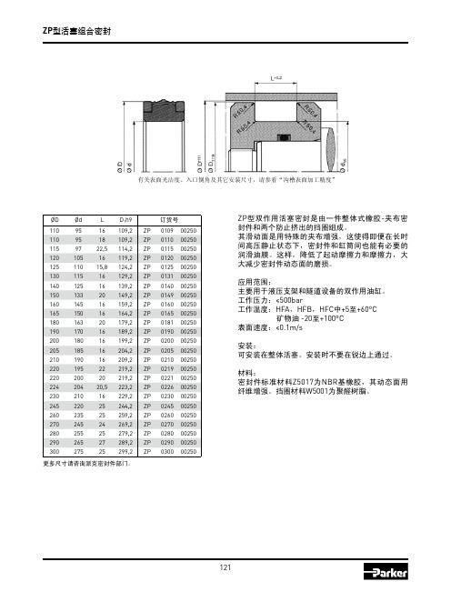
ZP型活塞组合密封
ZP型活塞组合密封
有关表面光洁度、入口倒角及其它安装尺寸,请参看“沟槽表面加工精度” 有关表面光洁度,入口倒角及其它安装时,请看“沟槽表面加工精度”。
D H9� ØD 110 110 115 120 125 130 140 150 160 165 180 190 200 205 210 220 220 224 230 245 260 270 280 290 300 Ød 95 95 97 105 110 115 125 133 145 150 163 170 180 185 190 195 200 204 210 220 235 245 255 265 275 L 16 18 22,5 16 15,8 16 16 20 16 16 20 16 16 16 16 22 20 20,5 16 25 25 24 25 27 25 D1h9 110� 109,2 110� 109,2 115� 114,2 120� 119,2 125� 124,2 130� 140� 129,2 150� 139,2 160� 149,2 165� 159,2 180� 164,2 190� 179,2 200� 189,2 205� 199,2 210� 204,2 220� 220� 209,2 224� 219,2 230� 219,2 245� 223,2 260� 229,2 270� 244,2 280� 259,2 290� 269,2 300� 279,2 289,2 299,2
派克液压密封件说明书

派克汉尼汾公司版权所有未经许可不能摘录,翻印。
保留修改权利2021年6月警告销售条件本样本中产品和/或系统或相关产品出现故障,选型不当或使用不当,均可能导致人身伤亡和财产损失。
本文档以及由派克·汉尼汾公司及其子公司和授权经销商提供的其他资料,为具有技术知识的用户提供进一步研究所需的产品和/或系统选项。
重要的是,用户必须对您的应用进行全面的分析,并对当前产品样本中与产品或系统相关的资料进行评估。
由于工作条件以及产品或系统的多样性,用户必须自行分析和测试,并独自承担一切后果,包括:产品和系统的最终选型以及确保满足应用的所有性能、安全和警告等方面的要求。
派克·汉尼汾及其子公司可能会随时对本样本中的产品,包括但不限于:产品的特性、产品的规格、产品的结构、产品的有效性以及产品的价格作出变更而不另行通知.本样本中的所有产品均由派克·汉尼汾公司及其子公司和援权经销商销售。
与派克签订的任何销售合同均按照派克标准条件和销售条件中规定的条款执行(提供复印件备索)。
本公司的密封件,只能在本公司的文件资料述及的应用参数范围与接触介质、压力、温度和存放时间相一致的情况下才能使用。
在规定的应用参数范围外使用以及错误选用不同的材料都可能导致密封件寿命的缩短以及设备的损坏,甚至更严重的后果(如生命安全,环境污染等)。
样本中所列出的工作压力、温度范围、运动速度是极限值,它们之间相互关联、相互影响;在极端的工况下,建议不要同时把各个参数都同时用到极限值。
对于特殊的要求(压力、温度、速度、介质等),请联系派克汉尼汾公司以咨询合适的密封结构、材料、配置、安装建议等。
由于诸多工作参数会影响到流体传动系统及密封元件,这些设备的制造商必须在实际工作条件下测试、验证并批准密封系统的功能与可靠性。
此外,对于不断出现的新的介质(液压油、润滑脂、清洗剂等),用户特别注意它们与目前所用的密封件弹性体材料的兼容性。
我们建议用户在大批量应用之前,在厂内或现场先做密封材料的兼容性能测试,作为密封产品与系统供应商,我们建议用户遵循我们的这些建议。
派克(parker) O形圈密封样本
!"
!O 14.00 mm 1.78 mm N674-70 !"# A70 O-Ring,14 x 1.78, 2-015, N674-70
7
2-xxx O
!
2-1xx
! d 1 (mm)
! d 2 = 2.62 mm
! d2 (mm) ! ! d 1 (mm) d2 (mm) ! ! d1 (mm) d 2 (mm)
2-xxx O O 100 C ! 12 O ! O
210 C)
!"#$%&'()
!"#
!
!"
C557-70
!" !"#$%#&'( !"#$%&'() ! !"#$%&'()*+ !"#$%"&'$( !"# !"#$ !"# !"#$%& !"#$%& !"#$%&' !"#$% !" !"#
P5008 A 93
. !" !"#$%& !"# O
!"
!"#$%&'( !"#$%&'() !"#O !"#$%& !"# ! O !"#$%&'( )*!"+,!"#$% !"# !"#$%&"' !"#$%&'()*+,-
!"#$%&'()* O !"#$%&'( !"#$%&'() 3
Parker PF系列非泄漏快速连接器产品介绍说明书
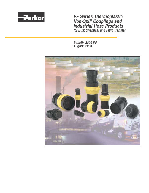
PF Series Thermoplastic Non-Spill Couplings and Industrial Hose Products for Bulk Chemical and Fluid TransferBulletin 3800-PFAugust,2004PF Series Non-Spill Quick CouplingsTypical ApplicationsQuick Coupling Features, Advantages and Benefits•Parker Quick Couplings automatically shut off on disconnection to reduce or eliminate spills and leaks •Flush face design exhibits minimal spillage and air inclusion upon connection or disconnection reducing system contamination •Available in sizes 1⁄2”, 1”, and 2”providing quality couplers for most applications •Lightweight and reliable push-to-connect operation reduces worker fatigue and increases productivity •Plastic composite will not scratch painted or finished surfaces reducing costly rework•Parker Quick Couplings offer flexibility and save time when frequent connection and disconnection is required•1⁄2” PF Couplers and nipples interchange with the Parker 1⁄2” FS Series stainless steel non-spill couplers and nipples.The FS Coupler provides durability for the end of transfer hoses while the PF offers all the advantages of a plastic coupler on the tank•1” coupler has non-wetted springs reducing system contamination and improving flow•Chemical Manufacturing and Distribution •Replacement for Camlok Style Fittings and Ball Valves•Herbicide, Insecticide and Pesticide Processing •Spray Application Equipment •Bulk Transfer Barrels •Mini Bulk Tanks•Chemical Transport and Handling •Pharmaceutical ManufacturingParker PF Series non-spill couplings virtually eliminate the possibility of accidental chemical leaks or spills when lines are connected or disconnected.This makes them the ideal choice whenever a closed system fluid transfer or dispensing process is desired.Constructed from glass filled polypropylene with PTFE coated fluorocarbon tank gaskets,they are inert to most chemicals.This means they provide excellent performance whenused on applicators,returnable containers or bulk storage tanks.T a n k M o u n t :C o u p l e r s :B o d y S i z e 1 i n c h P B o d y S i z e 1/2 i n c h1 i n c h2 i n c h B o d y S i z e 1/2 i n c h 1 i n c h S p e c i f i c a t i o n s :R a t e d P r e s s u r e P r e s s u r e D r o p F o r c e t o F o r c e t o O p e r a t i n g S t o r a g e M a x i m u m S p i l l a g e B o d y S i z eM a t e r i a l S p r i n g s S e a l s @ 68°F R a t e d F l o w a t R a t e d F l o w C o n n e c t D i s c o n n e c t T e m p e r a t u r e T e m p e r a t u r e p e r D i s c o n n e c t V a c u u m R a t i n g 1/2 i n c hP o l y p r o p y l e n e 316 S t a i n l e s s S t e e l F l u o r o c a r b o n 100 P S I 12 G P M 11.3 P S I 32 l b s 12 l b s +40°F t o +140°F -20°F t o +140°F 0.01 c u i n (0.14 m l )27.4 H g 1 i n c hP o l y p r o p y l e n e 316 S t a i n l e s s S t e e l F l u o r o c a r b o n 60 P S I 20 G P M 3.4 P S I 54 l b s 17 l b s +40°F t o +140°F -20°F t o +140°F 0.06 c u i n (1.0 m l )C o n s u l t F a c t o r y 2 i n c hP o l y p r o p y l e n e 316 S t a i n l e s s S t e e l F l u o r o c a r b o n100 P S I50 G P M4.0 P S I 41 l b s 17 l b s +40°F t o +140°F -20°F t o +140°F 0.18 c u i n (3.0 m l )C o n s u l t F a c t o r yParker Industrial Hose ProductsDynaFlex®PVC Standard Duty Suction HoseSeries 7560 is a versatile hose for agriculture, mining, construction, and industry.Warning: Elevated temperatures can change chemical resistance ratings. Check chemical concentration and compatibility.Other Quick Coupling ProductsHydraulic Quick Couplings • Various Configurations • Double Shut-Off • Single Shut-Off • Straight ThroughSwivels• Various End Configurations • In-Line Styles • 90°StylesCheck Valves • In-line Styles • Cartridge Styles • Split-flange Styles • 5,000 Configurations Bulletin 3800-PFQuick Couplings Parker Hannifin Corporation Quick Coupling Division 8145 Lewis Road Minneapolis,MN 55427Phone:763-525-4240Fax:763-544-3418Industrial Hose ProductsParker Hannifin Corporation Industrial Hose Products 17295 Foltz Industrial Parkway Cleveland,OH 44149Phone:440-286-2120Fax:440-286-2230/quickcouplingsPRINTED IN U.S.A. GR, MP 5M 08/04For additional information:Innovative Solutions with Unique Advantages:Pneumatic Quick Couplings • Industry Interchanges • Manual Connect • Push-to-Connect • Exhaust StylesThermoplastic Couplings • Various Sizes• Chemical Compatibility • Push-to-Connect • Non-Spill StylesDiagnostic Equipment • Digital Recording Meters • Digital Gauges• Diagnostic Quick Couplings • Sensors and Accessories。
parker派克密封件标准B7

øD ød
DøD d ødH
15 10 4.2
1620 8 105.7
LH ISO1)
4.7
6.36
ILSO2) 7●
订订货货号号
B7 1504 P5008
BB77 1060280AP50P058008
1625 10 155.7 6.36
20 12 4.2 4.7
2030 12 205.7 6.35
11 B7 A0B970 P058050B8 P5008
7 B7 B0B078 P058050C8 P5008
B7 B004 P5008
9 B7 B0B570 P058050D8 P5008
13 B7 C0B570 P058050E8 P5008
● ●
10
B7 B7
CC22B11705
PP055900000A88
7
BB77 3052540CP50P058008
33855.10
25 30.1
4075..37
687.3.3
8.3
BBB777 33058215500DPP5500P00588008
3950 29 407.3 89
10
BB77 3090590EP50P058008
440050
28 30
4071.03
70 6075 12 5513 12
75 6380 8.7 659.5 9
80 60 14.5 16
80 6580 8.6 659.5 10
80 6580 11.4 7102.5 6
80 70 6.7 7.5 ●
80 7080 12 7013
8
90 7580 11.4 4172.5 16
- 1、下载文档前请自行甄别文档内容的完整性,平台不提供额外的编辑、内容补充、找答案等附加服务。
- 2、"仅部分预览"的文档,不可在线预览部分如存在完整性等问题,可反馈申请退款(可完整预览的文档不适用该条件!)。
- 3、如文档侵犯您的权益,请联系客服反馈,我们会尽快为您处理(人工客服工作时间:9:00-18:30)。
美国Parker-PDF Z8、E4、PZ、EU、PP型汽缸密封圈一、DP型DP型缓冲式整体活塞是一种双U形密封和金属骨架硫化粘结的整体气动活塞.功能:密封,导向,缓冲.适用于顶端有缓冲的双作用汽缸.材质:邵氏硬度71度的NBR基橡胶,与金属骨架硫化粘接.工作介质:含润滑油的空气以及干燥空气和无油空气(装配初始需润滑)应用范围: 工作压力≤12bar,工作温度-30~+100℃,表面速度≤1m/s.规格尺寸(D*d*H/h) 订货号6*2*3.8/3 DP 0602 Z50518*3*5/4 DP 0803 Z505110*3*5/4 DP 1003 Z505112*4.5*6/4 DP 1203 Z505112*4.5*6/5 DP 1204 Z505116*4.5*6.5/4.5 DP 1603 Z505120*6*7.5/5.5 DP 2005 Z505120*6*7.5/6.3 DP 2006 Z505125*7*8.8/7 DP 2506 Z505132*8*11/8 DP 3208 Z505140*8*11.8/8.8 DP 4008 Z505150*10*14/10 DP 5010 Z505163*12*14/10 DP 6312 Z505180*16*16/12 DP 8016 Z5051100*20*18/14 DP A020 Z5051 E4型活塞密封件是一种专门用于气动设备的唇形密封件.E4型标准系列的尺寸符合ISO 3320,CETOP RP52P,RP43P,RP53P标准的缸径.E4型可以与C2型标准系列互换.标准材质:邵氏硬度A78的NBR基橡胶N3578. 工作介质:含润滑油的空气以及干燥空气和无油空气(装配初始需润滑)应用范围: 工作压力≤16bar,工作温度:-30~+80℃,表面速度≤1m/s规格尺寸(D*d*H) 订货号10*5*3 E4 1050 N357812*6*4 E4 1206 N357812*7*4 E4 1207 N357814*8*4 E4 1408 N357816*9*5 E4 1609 N357816*10*4 E4 1610 N357820*12*5.5 E4 2012 N357820*14*4 E4 2014 N357820.5*14*4 E4 2016 N357822*16*5 E4 2216 N357824*16*5.5 E4 2416 N357825*15.5*5.8 E4 2515 N357825*17*4.5 E4 2516 N357825*17*5.5 E4 2517 N357828*18*7 E4 2818 N357832*20*6.5 E4 3220 N357832*22*7 E4 3222 N357832*24*5.5 E4 3224 N3578 34*24*7 E4 3424 N357836*26*7 E4 3666 N357840*30*7 E4 4030 N357842*30*6 E4 4203 N357845*37*7 E4 4537 N357850*40*7 E4 5040 N357860*50*7 E4 6022 N357863*53*7 E4 6353 N357870*58*7 E4 7058 N357875*65*7.5 E4 7065 N3578 80*68*8.5 E4 8068 N3578 84*72*8.5 E4 8072 N3578 100*88*8.5 E4 A008 N3578 110*98*8.5 E4 B002 N3578 120*105*10 E4 C005 N3578 125*110*10 E4 C010 N3578 140*125*10 E4 E040 N3578 150*135*10 E4 F004 N3578 160*140*14 E4 G014 N3578 160*145*10 E4 G022 N3578 200*180*14 E4 L018 N3578 220*199*15 E4 M005 N3578 250*225*18 E4 N525 N3578 250*230*14 E4 N503 N3578 320*295*14 E4 Q205 N3578 320*295*17 E4 Q206 N3578 470*440*21 E4 R720 N3578 PZ型汽缸密封件用于汽缸和阀.标准材质:邵氏硬度A71度的NBR基合成橡胶. 工作介质:含润滑油的空气以及干燥空气和无油空气(装配初始需润滑)应用范围: 工作压力≤12bar,工作温度:-20~+100℃,表面速度≤1m/s规格尺寸(D*d*H) 订货号12*7*2 PZ 1207 N3571N16*9*2.1 PZ 1605 N3571N20*13*2.1 PZ 2013 N3571N25*18*2.1 PZ 2518 N3571N28*19*2.1 PZ 2819 N3571N30*21*2.5 PZ 3021 N3571N32*23*2.5 PZ 3210 N3571N40*31*2.5 PZ 4031 N3571N50*41*2.5 PZ 5010 N3571N63*51*3.4 PZ 6051 N3571N80*68*3.4 PZ 8010 N3571N100*88*3.4 PZ A008 N3571N125*110*4.4 PZ C050 N3571NZ8型活塞密封件是汽缸活塞用和阀用的唇形密封件.Z8型标准系列的尺寸符合ISO 3320,CETOP RP52P,RP43P,RP53P标准的缸径.Z8型可以与U型标准系列互换.标准材质:邵氏硬度A80的NBR基合成橡胶N3578.工作介质:含润滑油的空气以及干燥空气和无油空气(装配初始需润滑)应用范围: 工作压力≤16bar,工作温度:-30~+80℃,表面速度≤1m/s规格尺寸(D*d*H) 订货号4*1.5*1.5 Z8 0415 N35805*2.5*1.5 Z8 0504 N35806*3*2 Z8 0630 N35808*4*2.55 Z8 0804 N35808*4.8*2.3 Z8 0806 N358010*3*3.5 Z8 1003 N358010*6*2.55 Z8 1006 N358012*7*2.55 Z8 1207 N358013*8*2.55 Z8 1030 N358014*8*2.55 Z8 1421 N358015*9*2.55 Z8 1509 N358016*10*2.55 Z8 1610 N358016*11*2.55 Z8 1611 N358018*12*2.55 Z8 1812 N358020*14*2.55 Z8 2014 N358021*15*2.55 Z8 2115 N358022*16*2.55 Z8 2216 N3580 24*18*3.25 Z8 2418 N3580 25*19*3.25 Z8 2519 N3580 28*22*3.25 Z8 2822 N3580 30*22*3.25 Z8 3022 N3580 30*22.5*4.8 Z8 3023 N3580 32*24*3.25 Z8 3224 N3580 35*27*3.25 Z8 3527 N3580 36*28*3.25 Z8 3628 N3580 37*29*3.25 Z8 3729 N3580 38*30*3.25 Z8 3818 N3580 40*32*3.25 Z8 4032 N3580 42*34*3.25 Z8 4234 N3580 45*37*3.25 Z8 4522 N3580 50*42*3.25 Z8 5042 N3580 52*42*4.25 Z8 5205 N3580 57*50.5*4.25 Z8 5705 N3580 58*48*4.25 Z8 5816 N3580 63*53*4.25 Z8 6353 N3580 80*70*4.25 Z8 8070 N3580 90*80*4.25 Z8 9080 N3580 100*90*4.25 Z8 A090 N3580 125*105*8.25 Z8 C505 N3580 150*130*8.25 Z8 F113 N3580 160*140*8.25 Z8 G014 N3580 200*180*8.25 Z8 L018 N3580PZ型汽缸密封件用于汽缸和阀. 标准材质:邵氏硬度A71度的NBR基合成橡胶. 工作介质:含润滑油的空气以及干燥空气和无油空气(装配初始需润滑) 应用范围: 工作压力≤12bar,工作温度:-20~+100℃,表面速度≤1m/s 规格尺寸(D*d*H) 订货号 12*7*2 PZ 1207 N3571N 16*9*2.1 PZ 1605 N3571N 20*13*2.1 PZ 2013 N3571N 25*18*2.1 PZ 2518 N3571N 28*19*2.1 PZ 2819 N3571N 30*21*2.5 PZ 3021 N3571N 32*23*2.5 PZ 3210 N3571N 40*31*2.5 PZ 4031 N3571N 50*41*2.5 PZ 5010 N3571N 63*51*3.4 PZ 6051 N3571N 80*68*3.4 PZ 8010 N3571N 100*88*3.4 PZ A008 N3571N 125*110*4.4 PZ C050 N3571N Z8型活塞密封件是汽缸活塞用和阀用的唇形密封件. Z8型标准系列的尺寸符合ISO 3320,CETOP RP52P,RP43P,RP53P标准的缸径. Z8型可以与U型标准系列互换. 标准材质:邵氏硬度A80的NBR基合成橡胶N3578. 工作介质:含润滑油的空气以及干燥空气和无油空气(装配初始需润滑) 应用范围: 工作压力≤16bar,工作温度:-30~+80℃,表面速度≤1m/s 规格尺寸(D*d*H) 订货号4*1.5*1.5 Z8 0415 N35805*2.5*1.5 Z8 0504 N35806*3*2 Z8 0630 N35808*4*2.55 Z8 0804 N35808*4.8*2.3 Z8 0806 N358010*3*3.5 Z8 1003 N358010*6*2.55 Z8 1006 N358012*7*2.55 Z8 1207 N358013*8*2.55 Z8 1030 N358014*8*2.55 Z8 1421 N358015*9*2.55 Z8 1509 N358016*10*2.55 Z8 1610 N358016*11*2.55 Z8 1611 N358018*12*2.55 Z8 1812 N358020*14*2.55 Z8 2014 N358021*15*2.55 Z8 2115 N358022*16*2.55 Z8 2216 N358024*18*3.25 Z8 2418 N358025*19*3.25 Z8 2519 N358028*22*3.25 Z8 2822 N358030*22*3.25 Z8 3022 N3580 30*22.5*4.8 Z8 3023 N358032*24*3.25 Z8 3224 N358035*27*3.25 Z8 3527 N358036*28*3.25 Z8 3628 N358037*29*3.25 Z8 3729 N358038*30*3.25 Z8 3818 N358040*32*3.25 Z8 4032 N358042*34*3.25 Z8 4234 N358045*37*3.25 Z8 4522 N358050*42*3.25 Z8 5042 N358052*42*4.25 Z8 5205 N358057*50.5*4.25 Z8 5705 N358058*48*4.25 Z8 5816 N358063*53*4.25 Z8 6353 N358080*70*4.25 Z8 8070 N358090*80*4.25 Z8 9080 N3580100*90*4.25 Z8 A090 N3580 125*105*8.25 Z8 C505 N3580 150*130*8.25 Z8 F113 N3580 160*140*8.25 Z8 G014 N3580 200*180*8.25 Z8 L018 N3580。