WB300高性能蝶阀2012版 选型 样本 吴忠仪表
吴忠仪表蝶阀介绍

金相检测分析仪
3、轴孔加工
气动合镗工装,快速自动装夹 专用设备加工轴孔,高精高效作业。 轴孔合镗有效控制密封预紧力,正 反向具有优良密封性能
WB310中压蝶阀应用领域
石油和天然气处理
电厂 煤化工和石化工业 液化天然气、液化石油气
造纸
在制产品
在制产品
在制产品
WB300高性能蝶阀
蝶阀的技术特点
蝶阀完全开启时,具有较小的流阻,当开 启15~70度之间时,又能进行灵敏的流量控 制,因而在大口径的调节领域,蝶阀的应用 非常普遍,并逐渐成为主导阀型。阀板的背 面容易发生气蚀,有损坏阀门的可能,一般 均在15°外使用。 蝶阀的缺点如下: 1、使用压力和工作温度范围小。 2、密封性较差。
单偏心密封蝶阀结构
阀板的回转中心位于阀体的中心线上,且与阀板密封面形成 一个尺寸偏置。 阀门关闭时,阀座和阀板密封面处在有相对过盈的
接触状态,要达到密封主要是靠压紧密封圈使其在周边方向上膨胀产生密 封比压和管道压力对阀板的力,使其达到密封,所以只能单向密封。
阀体中心线 流道中心线 轴中心线 密封线 管道中心线
密封副由金属 硬质材料对金 属硬质材料构 成
蝶阀的分类
工作压力分
真空蝶阀
低压蝶阀
中压蝶阀
高压蝶阀
超高压蝶 阀
公称压力 工作压力低于 标堆大气历 PN<1.6MPa
公称压力PN 为2.5-6.4MPa
公称压力 PN为10-80MPa
公称压力 PN>100MPa
蝶阀的分类
工作温度分
高温蝶阀
中温蝶阀
常温蝶阀
阀门泄漏 1. 阀门未关到位 2. 阀门内有杂物 3. 密封面有损伤
KSB阀门说明书

ksb阀门简介德国ksb一、公司简介世界领先的阀门,执行机构和控制系统供应商之一。
1994年ksb进入中国并且与上海电气集团成立了合资公司。
进入中国10多年来,ksb在中国已经拥有4家分公司,900多名员工,和全国30多个服务网点和代理机构。
ksb在中国一共有四个公司分支:上海凯士比泵有限公司ksb 香港公司ksb 大连阀业有限公司ksb阀业有限公司并且,ksb在中国上海,广州,北京和成都所设立的华东,南方,北方和西部这四大销售中心的全国整体销售网络已正式形成。
.如今在中国,ksb已成为产品范围最广、技术水平最高的泵制造商之一。
在电站,石油,化工,城市给排水和污水处理,炼油,楼宇,船用及大型农田水利建设等领域享有很高的声誉。
在中国上海苏州河治理工程, 北京第九水厂, 南水北调工程, 巴斯夫工程, 拜耳工程, 大同电厂, 秦山核电站, 上海浦东国际机场, 上海金茂大厦, 上海f1国际赛车场, 北京东方广场等各著名工程项目中都有我们ksb的业绩。
产品质量和服务质量在ksb管理模式的指导下不断提高,为国内外客户提供优质服务,促进我国经济发展与改革开放,是我们ksb在中国一贯追求的目标。
德国ksb主要产品有:截止阀、过滤器、球阀、闸阀、疏水阀、蝶阀等通用阀门。
产品广泛用于:食品化工、纺织、塑胶、电子、木业、锅炉、烟草、电厂、聚酯、塑胶行业、化工行业、造纸行业等工业管道、蒸汽安装。
阀件产品的选择性很大,可根据整个应用范围来决定设计、规格和材料。
valves 总建筑量: 36座楼宇总体面积: 6000 平米.厂房面积: 1550 平米凯士比可以提供最高安全性能的阀门,应用于高温、高压、强腐蚀、高负荷流体的甚至应用于最恶劣环境中的工业工程。
ksb集团全资建立上海凯士比阀业有限公司组装基地 ksb集团全资建立大连阀业有限公司蝶阀生产基地二、典型案例1、凯士比第一时间为您提供最适宜的供水工程解决方案和措施。
工程简介上海浦东临江水厂,提供阀门型号如下:aquisoria, actair, smartronic, mammouth 上海市北水厂,提供阀门型号如下:aquisoria, actair, smartronic 青岛麦道水厂,提供阀门型号如下:aquisoria, actair, smartronic 2、凯士比为全球提供一级和二级电路最可靠的产品和服务。
ASB
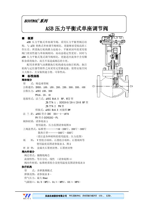
● 特殊检查 流量特性检查、材料检查(试验报告)、低温试验、蒸气试验、非破坏检查、放射线检查
●禁铜处理 ●完全除油、除水处理 ●指定色涂层 ●特殊空气配管和特殊接头 ●防砂、防尘型 ●防强腐蚀型 ●真空工作条件用 ●接触大气部分 SUS 不锈钢螺栓、螺母 ●寒带地区用 ●热带地区用
100
0.7043
50
0 0°C 50°C 100°C 150°C 200°C 250°C 300°C 350°C 400°C 450°C 500°C 550°C
Te m pe r atur e
温度
图 3:温压曲线
压力 (bar)
吴忠仪表股份有限公司 WUZHONG INSTRUMENT CO . . LTD .
30,0
B16.34/B16.35
20,0
10,0
0,0 0°C
100°C
200°C
300°C
Te温m度pe r atur e
400°C
500°C 300,0
ASME B16.34 600/900/1500
250,0
压力(bar) Pressure in bar
200,0
150,0
100,0
50,0
6.0
116
80
- 50.0 -
- 50.0 50.0 50.0 50.0 50.0
73
80
- 50.0 -
- 50.0 50.0 50.0 50.0 50.0
46
80
- 50.0 -
- 50.0 50.0 50.0 50.0 50.0
116
80
50.0 50.0 50.0 50.0 50.0 50.0 50.0 50.0 50.0
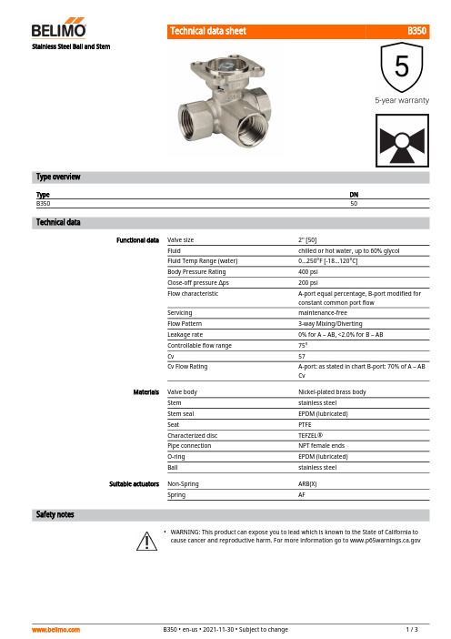
Belimo B350 50型号3路混合 分流阀数据表说明书
B350•Stainless Steel Ball and StemType overviewType DNB35050Technical dataFunctional data Valve size2" [50]Fluid chilled or hot water, up to 60% glycolFluid Temp Range (water)0...250°F [-18...120°C]Body Pressure Rating400 psiClose-off pressure ∆ps200 psiFlow characteristic A-port equal percentage, B-port modified forconstant common port flowServicing maintenance-freeFlow Pattern3-way Mixing/DivertingLeakage rate0% for A – AB, <2.0% for B – ABControllable flow range75°Cv57Cv Flow Rating A-port: as stated in chart B-port: 70% of A – ABCvMaterials Valve body Nickel-plated brass bodyStem stainless steelStem seal EPDM (lubricated)Seat PTFECharacterized disc TEFZEL®Pipe connection NPT female endsO-ring EPDM (lubricated)Ball stainless steelSuitable actuators Non-Spring ARB(X)Spring AFSafety notesWARNING: This product can expose you to lead which is known to the State of California tocause cancer and reproductive harm. For more information go to B350ApplicationMode of operationProduct featuresThis valve is typically used in air handling units on heating or cooling coils, and fan coil unit heating or cooling coils. Some other common applications include Unit Ventilators, VAV box re-heat coils and bypass loops. This valve is suitable for use in a hydronic system with variable or constant flow.Flow/Mounting detailsProduct featuresLocal Control SY2~12, 110vac ModDimensionsType DN B35050ARB, ARXAB C D E F H110.5" [267]4.9" [125]7.7" [196]6.0" [152]1.7" [44]2.6" [66]0.8" [20]ARB N4, ARX N4AB C D E F 11.4" [289]4.9" [125]9.8" [249]8.0" [203]3.1" [80]3.1" [80]B350ARQB, ARQXA B C D E F H1H29.9" [251] 4.9" [125]8.3" [211] 6.6" [168] 2.3" [58] 2.6" [66]0.8" [20]0.6" [15]AFRB, AFRXA B C D E F11.3" [286] 4.9" [125]8.3" [211] 6.6" [168] 2.6" [66] 2.6" [66]AFRB N4, AFRX N4A B C D E F13.0" [330] 4.9" [125]11.8" [300]9.9" [251] 3.7" [95] 3.7" [95]ARX24-3-T N4FootnotesNEMA 4X, On/Off, Floating Point Control, Non-Spring Return, 24 VTechnical dataElectrical dataNominal voltageAC/DC 24 V Nominal voltage frequency 50/60 Hz Power consumption in operation 2.5 W Power consumption in rest position 0.5 WTransformer sizing 5.5 VA (class 2 power source)Electrical Connection Terminal blocksOverload Protectionelectronic thoughout 0...90° rotation Functional dataDirection of motion motor selectable with switch 0/1Manual override under cover Angle of rotation 90°Angle of rotation note adjustable with mechanical stop Running Time (Motor)90 s / 90°Running time motor variable 90 or 150 s Noise level, motor 45 dB(A)Position indicationpointer Safety dataDegree of protection IEC/EN IP66/67Degree of protection NEMA/UL NEMA 4XEnclosure UL Enclosure Type 4XAgency ListingcULus acc. to UL60730-1A/-2-14, CAN/CSA E60730-1:02, CE acc. to 2014/30/EU and 2014/35/EU Quality Standard ISO 9001Ambient temperature -22...122°F [-30...50°C]Ambient temperature note -40...50°C for actuator with integrated heating Storage temperature -40...176°F [-40...80°C]Ambient humidity Max. 100% RH Servicingmaintenance-freeMaterialsHousing material Die cast aluminium and plastic casing†Rated Impulse Voltage 800V, Type of action 1, Control Pollution Degree 4.Electrical installationINSTALLATION NOTESProvide overload protection and disconnect as required.Actuators may be connected in parallel. Power consumption and input impedance must beobserved.Actuators may also be powered by DC 24 V.ARX24-3-T N4Actuators Hot wire must be connected to the control board common. Only connect common toneg. (-) leg of control circuits. Terminal models (-T) have no-feedback.Actuators are provided with a numbered screw terminal strip instead of a cable.Meets cULus requirements without the need of an electrical ground connection.Warning! Live electrical components!During installation, testing, servicing and troubleshooting of this product, it may be necessaryto work with live electrical components. Have a qualified licensed electrician or other individualwho has been properly trained in handling live electrical components perform these tasks.Failure to follow all electrical safety precautions when exposed to live electrical componentscould result in death or serious injury.Wiring diagramsOn/Off Floating PointFloating Point - Triac Source Floating Point - Triac SinkDimensions。
西门子 VVF61 法兰连接二通阀说明书

4382二通阀法兰连接, PN40VVF61...DN15 和DN25 DN40…DN150法兰连接二通阀,耐压等级 PN40• 公称直径: DN15…DN150 mm• 阀体DN15和DN25: 铸钢GS-C 25 N• 阀体DN40…DN150: 铸钢GS-45• 流量: k vs 0.19…300 m3/h• 阀杆行程: 20 或40 mm• 可与SQX..., SKD... 和 SKB... 系列执行器配合安装适用于区域供热系统、暖通空调系统中作为符合DIN 32730标准的控制阀或安全截止阀。
适用于开式系统和闭式系统。
用途介质采用标准密封的标准阀门适用于以下介质:冷却水冷冻水低温热水高温热水防冻水1) 2)−25…+220 °C标准蒸汽/过热蒸气DN15和25 (最高达到17 bar abs.)DN40…150 (最高达到11 bar abs.)盐水1) 2)带绝热器和采用特殊密封的特殊阀门适用于以下介质:耐热油220…300/350 °C3)制冷剂不适用4)1) 介质温度低于0°C时:需要ASZ6.5阀杆加热元件来防止密封套内的阀杆冻结。
2) 防冻水和盐水:最低-10°C 符合DIN 3158标准(压力容器 I) 或 最低-25°C 符合DIN 3158标准(压力容器 II) 。
3) 对于220…300/350 °C 耐热油的应用, 在阀与执行器之间要求有绝热器。
根据阀体材料所允许的最高温度在“注意事项”和“工程注意事项”中有所说明。
4) 对于这些应用,应使用带电磁式执行器的特制制冷剂阀,请参见技术资料 4700 (4799)Siemens Building Technologies CM1N4382C / 03.2003HVAC Products 1/8型号概览标准版本型号DN kS v∆p vmax.vs[mm] [m3 /h] [KPa]VVF61.09 15/1 0.19VVF61.10 15/1.5 0.3VVF61.11 15/2.5 0.45VVF61.12 15/4 0.7VVF61.13 15/6 1.2 >50VVF61.14 15/10 1.9VVF61.15 15 3 1600VVF61.23 25/15 3VVF61.24 25/20 5VVF61.25 25 7.5 >100VVF61.39 40/32 12 >50VVF61.40 40 19VVF61.50 50 31VVF61.65 65 49 1000VVF61.80 80 78 >100 700VVF61.90 100 124 450VVF61.91 125 200 300VVF61.92 150 300 200特殊版本 (型号有后缀数字2)适用介质和温度范围实例:耐热油220…300/350 °C VVF61.502 1)1) 温度范围220 °C…300/350 °C 的耐热油要求带有绝热器的特殊版本(型号后缀2)DN =公称直径∆p vmax. =当阀杆到达最大行程时k vs=符合VDI 2173标准的额定流量(阀门全开),阀门S v=符合VDI 2173标准的流通能力两端允许的最大压差电子阀杆加热元件, AC 24 V, 介质温度低于0 °C时需选用: ASZ6.5附件订货订货时,请说明型号和型号后缀(有需要时)。
轴流阀说明书.

A2000 轴流调节阀产品使用说明书吴忠仪表有限责任公司A2000轴流调节阀概述A2000轴流式调节阀是一种压力平衡式套筒调节阀。
该阀可广泛适用于天然气石油化工等要求压降损失小、流量大、动态稳定性好、噪音低、空化腐蚀小的场合。
A2000轴流阀的主要特点如下:-阀芯是压力平衡式的,即使大口径的阀在高压降件下,也可以用较小的执行机构对其进行操作。
-阀体内腔是直通流线型的,大大减小了流动阻力。
-阀芯与阀体的同心的运动方式大大降低了紊流引起的震动和噪声。
-密封系统由软硬双层结构组成。
软密封可达到气泡级密封,即使在软密封遭到破坏,硬密封也可达到Ⅴ级密封。
-阀内组件经过渗氮处理,具有抗冲刷、耐磨损等特点。
A2000轴流阀技术参数和性能阀体型式:直通铸造桶形阀公称通径:100-500公称压力:ANSI 150 300 400 600连接形式:法兰式:RF、RJ标准按API6D ANSI B16.5焊接式:BW材料:ZG25I ZG1Cr18Ni9上阀盖:常温式:-17o C-+120o C阀内组件阀芯形式:压力平衡式流量特性:线性、等百分比材料:17-4PH 3Cr13+N2执行机构 DN100~DN200直行程电动执行机构、 DN250~DN500多回转电动执行机构作用形式电开式或电关式附件定位器、阀位传送器、手轮机构性能泄漏量:符合ANSI B16.104 Ⅵ级、小于额定Cv的10 线性:±5%(不带定位器)±1%(带定位器)回差:3%(不带定位器)1%(带定位器)可调范围 100:1安装包装大多数轴流阀从工厂运输来直接安装使用。
阀在运送过程中是关闭的。
如果阀和执行机构分开装箱,请遵循摆放指导。
库存将阀体覆盖以防灰尘和杂质侵入阀体,并保护法兰密封区域和法兰端及焊接部位免受机械损伤。
如何保护好移去覆盖物准备安装的阀体不被损坏很重要。
执行机构使用前去掉覆盖物;不连接动力源时,请保持其原样不动。
阀门流阻系数
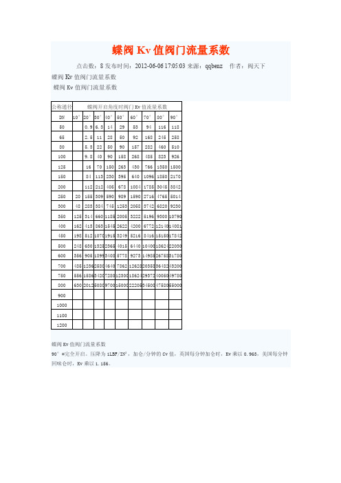
点击数:8 发布时间:2012-06-06 17:05:03 来源:qqbenz 蝶阀 Kv 值阀门流量系数 蝶阀 Kv 值阀门流量系数
作者:阀天下
公称通径
蝶阀开启角度时阀门 Kv 值流量系数
DN 10° 20° 30° 40° 50° 60° 70° 80° 90°
50
0.9 6.3 14 29 53 94 116 118
900
1000
1100
1200
蝶阀 Kv 值阀门流量系数 90°=完全开启。压降为 1LBF/IN²,加仑/分钟的 Cv 值,英国每分钟加仑时,Kv 乘以 0.963,美国每分钟 回味仑时,Kv 乘以 1.156。
阀门压力损失计算公式
公式 1.
△P=(Q/Kv) ^2
公式 2. 公式 3. 公式 4.
200
112 212 405 678 1084 1785 3045 3842
250 20 155 309 590 989 1590 2716 4765 5014
300 48 283 384 745 1253 2058 3742 6820 9230
350 125 314 660 1185 2005 3222 5196 9300 10790
△P=压力损失,
bar
Q=流量,
m ^3/h
Kv=(额定压差 1bar), m ^3/h
△P=0.0102×(Q/Kv) ^2
△P=压力损失,
mm 水柱
Q=流量,
l/h
Kv=(额定压差 1bar),
m ^3/h
△P=0.01×(Kv0.01)^2
△P=压力损失,
bar
Q=流量,
Dwyer Series DS-300 平均钢管传感器说明书
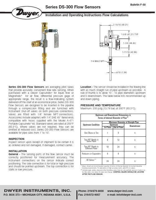
Series DS-300 Flow Sensors are averaging pitot tubes that provide accurate, convenient flow rate sensing. When purchased with a Dwyer Capsuhelic®for liquid flow orfor air flow, differential pressure gage of appropriate range, the result is a flow-indicating system delivered off the shelf at an economical price. Series DS-300 Flow Sensors are designed to be inserted in the pipeline through a compression fitting and are furnished with instrument shut-off valves on both pressure connections. Valves are fitted with 1/8˝ female NPT Accessories include adapters with 1/4˝ SAE 45°compatible with hoses supplied with the Model A-471®kit. Standard valves are rated at 200°F (93.3°C). Where valves are not required, they can be omitted at reduced cost. Series DS-300 Flow Sensors are available for pipe sizes from 1˝ to 10˝.LPHP1-7/16 (36.53)SENSORFLOWPIPE1/16 (1.59)CLEARANCEHPLPLP DRAIN HP DRAIN.20.40.60.801.0INCHES OF WATERCAPSUHELIC ®MAX. OPERATING PRESS. 500 PSIGZERO SETDWYER INSTRUMENTS, INC. MICHIGAN CITY, INDIANA 46360 U.S.A.UPPER PIPE QUADRANTLOWER PIPE QUADRANTFor Air or Gas Flow Install in upper quadrant of pipeCondensate drains back to pipeFor Liquid or Steam Flow Install in lower quadrant of pipeAir bleeds back to pipeLP BLEEDHP BLEEDPIPE1/16 (1.59)CLEARANCEFLOWSENSOR1-7/16 (36.53)LPHPHPLP INCHES OF WATERCAPSUHELIC ®ZERO SETMAX. OPERATING PRESS. 500 PSIG.60.801.0.40.200DWYER INSTRUMENTS, INC MICHIGAN CITY, INDIANA 46360 U.S.A.Water FlowAir or Gas FlowINSTALLATION1. When using an A-160 thred-o-let, weld it to the pipe wall.If replacing a DS-200 unit, an A-161 bushing (1/4˝ x 3/8˝) will be needed.2. Drill through center of the thred-o-let into the pipe with a drill that is slightly larger than the flow sensor diameter.3. Install the packing gland using proper pipe sealant. If the packing gland is disassembled, note that the tapered end of the ferrule goes into the fitting body.4. Insert sensor until it bottoms against opposite wall of the pipe, then withdraw 1/16˝ to allow for thermal expansion.5. Tighten packing gland nut finger tight. Then tighten nut with a wrench an additional 1-1/4 turns. Be sure to hold the sensor body with a second wrench to prevent the sensor from turning.INSTRUMENT CONNECTIONConnect the slide pressure tap to the high pressure port of the Magnehelic ®(air only) or Capsuhelic ®gage or transmitting instrument and the top connection to the low pressure port.See the connection schematics below.Bleed air from instrument piping on liquid flows. Drain any condensate from the instrument piping on air and gas flows. Open valves to instrument to place flow meter into service.For permanent installations, a 3-valve manifold is recommended to allow the gage to be zero checked without interrupting the flow. The Dwyer A-471 Portable Test Kit includes such a device.POSITIONBe certain there is sufficient clearance between the mounting position and other pipes, walls, structures, etc, so that the sensor can be inserted through the mounting unit once the mounting unit has been installed onto the pipe.Flow sensors should be positioned to keep air out of the instrument connecting lines on liquid flows and condensate out of the lines on gas flows. The easiest way to assure this is to install the sensor into the pipe so that air will bleed into,or condensate will drain back to, the pipe.1-3/4 (44.45)1-11/16 (42.86)1-5/8 (41.27) TYP1-15/16 (49.21)LPHP1/4 MALE NPT5/16 (7.94)Using the appropriate differential pressure equation from Page 4 of this bulletin,calculate the differential pressure generated by the sensor under normal operating conditions of the system. Check the chart below to determine if this value is within the recommended operating range for the sensor. Note that the data in this chart is limited to standard conditions of air at 60°F (15.6°C) and 14.7 psia static line pressure or water at 70°F (21.1°C). To determine recommended operating ranges of other gases, liquids an/or operating conditions, consult factory.Note:the column on the right side of the chart which defines velocity ranges to avoid. Continuous operation within these ranges can result in damage to the flow sensor caused by excess vibration.Flow Calculations and ChartsThe following information contains tables and equations for determining the differential pressure developed by the DS-300 Flow Sensor for various flow rates of water, steam, air or other gases in different pipe sizes.This information can be used to prepare conversion charts to translate the differential pressure readings being sensed into the equivalent flow rate. When direct readout of flow is required, use this information to calculate the full flow differential pressure in order to specify the exact range of Dwyer Magnehelic ®or Capsuhelic ®gage required. Special ranges and calculations are available for these gages at minimal extra cost. See bulletins A-30 and F-41 for additional information on Magnehelic ®and Capsuhelic ®gages and DS-300 flow sensors.For additional useful information on making flow calculations, the following service is recommended: Crane Valve Co. Technical Paper No. 410 “Flow of Fluids Through Valves, Fittings and Pipe.” I t is available from Crane Valve Company, .Pipe Size (Schedule 40)11-1/41-1/222-1/2346810Flow Coefficient “K”0.520.580.580.640.620.670.670.710.670.70Operating Ranges Air @ 60°F & 14.7 psia(D/P in. W.C.)1.10 to 1861.15 to 1570.38 to 1150.75 to 751.72 to 530.39 to 350.28 to 340.64 to 110.10 to 100.17 to 22Operating Ranges Water @ 70°F (D/P in. W.C.)4.00 to 6754.18 to 5681.36 to 4172.72 to 2716.22 to 1931.43 to 1271.02 to 1232.31 to 400.37 to 370.60 to 79Velocity Ranges Not Recommended (Feet per Second)146 to 220113 to 17096 to 14471 to 10856 to 8542 to 6428 to 4315 to 239.5 to 156.4 to 10DWYER INSTRUMENTS, INC.Phone: 219/P .O. BOX 373 • MICHIGAN CITY, INDIANA 46361, U.S.A.Fax: 219/872-9057e-mail: info@©Copyright 2004 Dwyer Instruments, Inc. Printed in U.S.A. 7/04 FR# 72-440451-01 Rev. 2FLOW EQUATIONS1. Any LiquidQ (GPM) = 5.668 x K x D 2x ∆P/S f2. Steam or Any GasQ (lb/Hr) = 359.1 x K x D 2xp x ∆P3. Any GasQ (SCFM) = 128.8 x K x D 2x P x ∆P(T + 460) X S SDIFFERENTIAL PRESSURE EQUATIONS1. Any Liquid∆P (in. WC) = Q 2x S fK 2x D 4x 32.142. Steam or Any Gas∆P (in. WC) = Q 2K 2x D 4x p x 128,9003. Any Gas∆P (in. WC) = Q 2x S S x (T + 460)K 2x D 4x P x 16,590Technical NotationsThe following notations apply:∆P = Differential pressure expressed in inches of water columnQ = Flow expressed in GPM, SCFM, or PPH as shown in equation K = Flow coefficient— See values tabulated on Pg. 3.D = Inside diameter of line size expressed in inches.For square or rectangular ducts, use: D = 4 x Height x WidthπP = Static Line pressure (psia)T = Temperature in degrees Fahrenheit (plus 460 = °Rankine)p = Density of medium in pounds per square foot S f = Sp Gr at flowing conditions S S = Sp Gr at 60°F (15.6°C)SCFM = ACFM X ( 14.7 + PSIG)(520* )14.7460 + °F ACFM = SCFM X(14.7)(460 + °F )14.7+ PSIG520POUNDS PER STD. = POUNDS PER ACT. X( 14.7 )( 460 + °F )CUBIC FOOT CUBIC FOOT14.7 + PSIG 520*POUNDS PER ACT. = POUNDS PER STD. X (14.7 + PSIG)(520*)CUBIC FOOT CUBIC FOOT14.7460 + °F1 Cubic foot of air = 0.076 pounds per cubic foot at 60°F (15.6°C) and 14.7 psia.* (520°= 460 + 60°) Std. Temp. RankineSCFM TO ACFM EQUATION。