流量控制阀说明书
IC卡流量控制阀使用说明书

IC卡流量控制阀使用说明书IC卡流量控制阀一、产品简介我公司生产的IC卡流量控制阀是与气体流量计配套使用的一种微功耗电动球阀,属软密封阀门。
该产品采用微型电机作动力,通过减速装置放大扭矩,由执行机构实现行程控制,再由螺纹传动装置转化成直线运动,并基于轨道控制原理来实现关阀与开阀动作。
该控制阀克服了传动球阀诸多缺陷,具有结构合理,性能稳定,使用方便,功耗低、寿命长,密封效果好等特点,属于节能环保型产品。
并采用隔爆结构设计,具有防爆性能,可在爆炸性气体环境中使用。
该控制阀可与流量计配合组成智能IC卡气体控制系统,可广泛用于流体管道的工业自动化控制系统和城市燃气管道终端预收费系统及气体管道系统的自动控制。
我公司根据不同的市场特点,分别开发出普通球阀隔爆结构型、轨道球阀隔爆结构型、轨道球阀普通结构型等三种结构型式可供选择,满足客户的不同使用需求。
目前,该IC卡流量控制阀已经获得国家实用新型专利证书,专利号:ZL 2012 2 0021062.7。
二、产品特点·零压损结构设计,采用球阀结构,阀门通径与管道直径相当。
·启闭件结构设计新颖独特,密封性能好,阀杆扭矩小,无内漏。
·主轴轨道行程控制,结构先进,制作精密。
·阀芯有限联接结构或浮动固定,稳定可靠。
·微电机做动力源,大扭矩传动,功耗低,耗电量低,电池寿命长。
·采用隔爆型电气防爆设计,杜绝电动阀门的安全隐患。
IC卡流量控制阀使用说明书·阀体部件表面阳极氧化或喷漆,美观清洁,具有防腐性能。
·采用航空插座接头,装配,安全可靠。
三、产品技术参数1、公称通径:DN25~DN200 mm;2、工作压力:①DN 10~DN100,最高工作压力0.6MPa;②DN150~DN200,最高工作压力0.4MPa;注:特殊定制DN 25~DN100,最高工作压力0.8MPa;3、工作电流:≤200mA;4、工作电源:7.2VDC;5、使用温度:-20~+60℃6、防爆标记:EX d ⅡB T4 Gb7、防爆证号:GYB12.1218X8、防护等级:IP659、开阀时间:附表规格≤DN25 DN50 DN80 DN100 DN150 DN200关阀时<15 <100 <200 <360 <400 <500 间(s)开阀时<15 <100 <200 <360 <400 <500 间(s)四、产品型式代号例如:TCVL-B-50-1.6-0.8表示产品型号为TCVL- B、结构形式为轨道球阀隔爆,公称尺寸为DN50、公称压力为1.6MPa、最大工作压力为0.8MPa 的IC卡流量控制阀。
VNA系列 流体控制阀 说明书
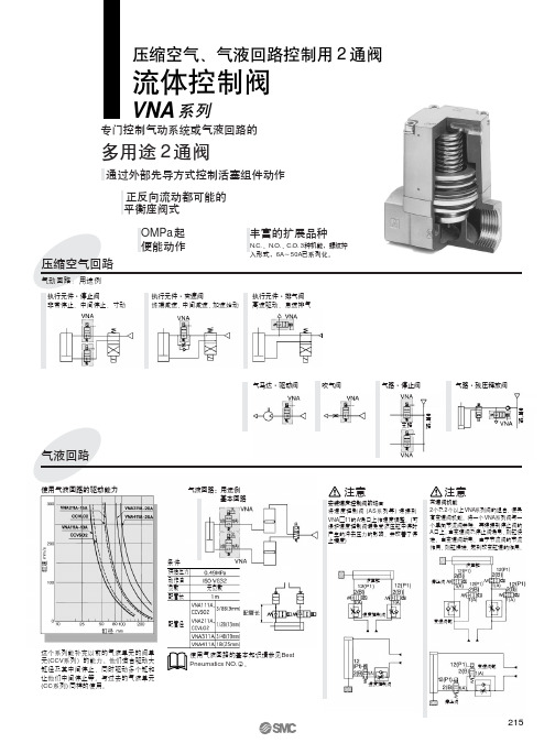
构成零部件
序号 ① ② ③ ④ ⑤ ⑥ ⑦ ⑧ 零部件名 阀体 阀盖组件 隔板组件 阀芯 活塞组件 动作弹簧 复位弹簧 电磁先导阀 材质 铝合金 铝合金 铝合金 铝合金 铝合金 不锈钢 钢丝 备注 涂铂银色 涂铂银色 密封件材质(NBR、 FKM、 EPR) 密封件材质(NBR、 FKM、 EPR)
(DIN形插座式:D)
( 直接出线式:G)
( 导管式:C)
主通口
型号
主通口
先导口
(气控型)
219
VNA
产品各自注意事项
使用前必读。安全上的注意、共同注意事项由后附 1~8 确认。
关于外部先导式
作为气液型使用的场合
VNA系列和流量控制阀(AS系列)的组合
配管(内径)
¿ ¿ ¿ ¿ ¿ ¿ ¿
注意
通口 外部 先导口 呼吸口 呼吸口 外部 先导口 外部 先导口 外部 先导口 外部 先导口 先导 排气口
线圈额定电压 1 2 ※3 ※4 5 ※6 ※7 ※9 其他 ※准标准
手动操作方式 按钮式安全型 无记号 按钮式凸出型 锁式要工具型 ※准标准
导线引出方式、带指示灯及过 电压保护回路 直接出线式 带过电压保护回路、直接出线式 接线座出线式 带指示灯及过电压保护回路、 接线座出线式 导管接线座式 带指示灯及过电压保护回路、 导管接线座式 DIN形插座式 带指示灯及过电压保护回路、 DIN形插座式
气)降低,复位弹簧使阀芯关闭。 VNA□02□、□12□(N.O.型)的场合 与 N.C.型相反,电磁先导阀不通电时(气控型从 10(P2)通口排气),复位 弹簧使阀芯开启。电磁先导阀通电时(气控型从10(P2)通口加压),阀芯 关闭。 VNA□03□(C.O.型) C.O.型由于没有复位弹簧, 12(P1)、10(P2)通口处排气状态时,阀芯处 任意位置。 12(P1)通口一加压(10(P2)通口排气),阀芯开启;10(P2)通口 加压(12(P1)通口排气),阀芯关闭。
rexroth RE 18702型号比例流量控制阀说明书
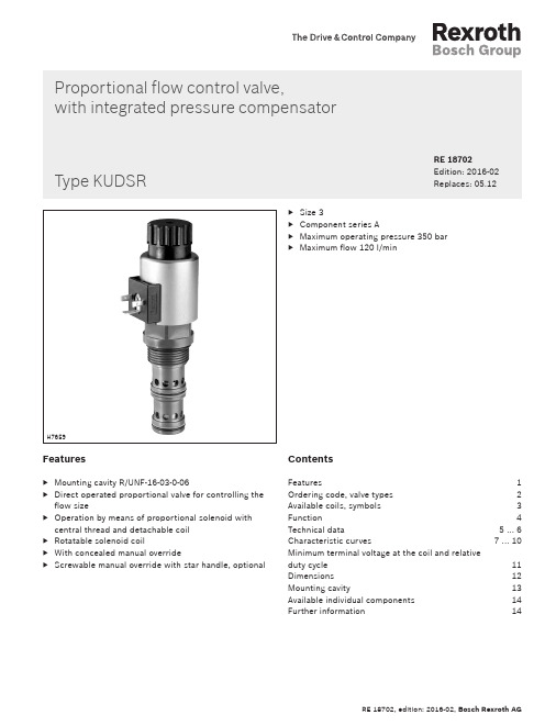
Proportional flow control valve,with integrated pressure compensatorFeatures▶Mounting cavity R/UNF-16-03-0-06▶Direct operated proportional valve for controlling the flow size▶Operation by means of proportional solenoid with central thread and detachable coil ▶Rotatable solenoid coil▶With concealed manual override▶Screwable manual override with star handle, optionalContentsFeatures 1Ordering code, valve types 2Available coils, symbols 3Function 4Technical data 5 ... 6Characteristic curves 7 ... 10Minimum terminal voltage at the coil and relative duty cycle 11Dimensions 12Mounting cavity 13Available individual components 14Further information 14▶Size 3▶Component series A▶Maximum operating pressure 350 bar▶Maximum flow 120 l/minRE 18702Edition: 2016-02Replaces: 05.12H7659Type KUDSR2/14KUDSR | Proportional flow control valve 01Proportional flow control valve, with integrated pressure compensator, direct operatedKUDS 02Maximum operating pressure 350 bar R 03Size 3305Component seriesA 06High Performance and mounting cavity R/UNF-16-03-0-06, see page 13F 07With concealed manual override 2)N9Seal material 08FKM sealsV(other seals upon request) Attention! Observe compatibility of seals with hydraulic fluid used!09Further details in the plain text*010203040506070809KUDSR 3A /F N9V *Type Material no.KUDSR3CA/FN9V R901255657KUDSR3C1A/FN9V R901287409KUDSR3C2A/FN9VR901265879Valve types (without coil) 1)1) Complete valves with mounted coil on request.2)Screwable manual override with star handle "N14"(separate order, material no. R913009058, see page 12).Proportional flow control valve | KUDSR 3/143) Mating connectors, separate order, see data sheet 08006.4)Other voltages upon request.Available coils (separate order) 1)Direct voltage DC 4)Material no. for coil with connector 3)"K4" 03pol (2+PE) DIN EN 175301-803"K40" 02pol K40DT 04-2PA, co. Deutsch"C4"02pol C4/Z30 AMP Junior-Timer 12 V (1.8 A)R901022180R901272648R90102268024 V (1.2 A)R901022174R901272647R901022683Symbols① = Main port 1 (P)② = Main port 2 (T)① = Main port 3 (A)14/14KUDSR | Proportional flow control valveGeneralThe proportional flow control valve is a direct operated screw-in cartridge valve in spool design with integrated pressure compensator. It regulates the flow proportionally to the input signal in a stepless form from main port ① to ②. Any excessive residual flow is led to the tank or to another actuator via port ②.The valve basically consists of housing, control spool,control spring, pressure compensator piston, orifice bush, pressure compensator spring as well as proportional solenoid (1) with central thread and detachable coil.FunctionVersion "C4"Type KUDSR3…①②①FunctionWith de-energized proportional solenoid (1), the control spool that is always pressure-compensated to the actuat -ing forces due to its structural design is held in the initial position by the control spring and blocks the flow between main port ① and ③. By energizing the proportionalsolenoid (1), the control spool is adjusted directly propor -tional to the electrical input signal and, via orifice-type cross-sections (with progressive flow characteristics), adjusts and connects the main ports ① and ③. Due to the integrated pressure compensator piston together with the pressure compensator spring, the pressure drop across the valve is kept constant, independent of the pressures at ①, ② and ③. In case of excessive flow from ①, the pres -sure compensator piston moves to the right and opens the connection ① to ②. In case of de-excitation of the propor -tional solenoid (1), the control spring returns the control spool into its initial position. The entire flow is now directly led from main port ① to main port ②The manual override (2) allows for the adjustment of the valve without solenoid energization.Proportional flow control valve | KUDSR 5/14Technical data(For applications outside these parameters, please consult us!)1)The cleanliness classes specified for the components must be adhered to in hydraulic systems. Effective filtration prevents faults and simultaneously increases the life cycle of the components.Available filters can be found at /filter.Environmental auditsSalt spray test according to DIN 50021h 720Surface protection DC solenoids Coating according to DIN 50962-Fe//ZnNi with thick film passivation Hydraulic fluid Classification Suitable sealing materials Standards Mineral oils HL, HLP FKM DIN 51524Bio-degradable▶Insoluble in water HEES FKM VDMA 24568▶Soluble in waterHEPGFKMfluids, please refer to data sheet 90220 or contact us!▶There may be limitations regarding the technical valve data (temperature, pressure range, life cycle, maintenance intervals, etc.)!▶The flash point of the hydraulic fluids used has to be 40 K above the maximum solenoid surface temperature.▶Bio-degradable: If bio-degradable hydraulic fluids are used that are also zinc-solving, there may be an accumulation of zinc.2)Measured with analog amplifier type RA2-1/10 according to data sheet 95230 (PWM = 100 Hz).6/14KUDSR | Proportional flow control valveTechnical data(For applications outside these parameters, please consult us!)standards ISO 13732-1 and ISO 4413 need to be adhered to!024620406080100135Proportional flow control valve | KUDSR 7/14Characteristic curves(measured with HLP46, ϑoil = 40 ± 5 °C and 24 V coil)Flow in l/min →P r e s s u r e d i f f e r e n t i a l i n b a r →∆p -q V characteristic curve – main port ① to ② (③ open, orifice closed)5010015020025030035010203040506070809010005010015020025030035010203040506070809010001020304050607080901020304050607080901008/14KUDSR | Proportional flow control valveCharacteristic curves: Version "C"(measured with HLP46, ϑoil = 40 ± 5 °C and q V ① = 80 l/min)Load pressure in bar →Load pressure in bar →Command value in % →F l o w i n l /m i n →F l o w i n l /m i n →F l o w i n l /m i n →Regulated flow at main port ③ as a function of the load pressure 3-way function (main port ② open to the tank)Regulated flow at main port ③ as a function of the load pressure 2-way function (main port ② closed)Regulated flow at main port ③ as a function of the command value5010015020025030035010203040506070800501001502002503003501020304050607080010203040506070102030405060708090100Proportional flow control valve | KUDSR 9/14Characteristic curves: Version "C1"(measured with HLP46, ϑoil = 40 ± 5 °C and q V ① = 60 l/min)Load pressure in bar →Load pressure in bar →Command value in % →F l o w i n l /m i n →F l o w i n l /m i n →F l o w i n l /m i n →Regulated flow at main port ③ as a function of the load pressure 3-way function (main port ② open to the tank)Regulated flow at main port ③ as a function of the load pressure 2-way function (main port ② closed)Regulated flow at main port ③ as a function of the command value0501001502002503003501020304050600501001502002503003501020304050600102030405010203040506070809010010/14KUDSR | Proportional flow control valveCharacteristic curves: Version "C2"(measured with HLP46, ϑoil = 40 ± 5 °C and q V ① = 40 l/min)Load pressure in bar →Load pressure in bar →Command value in % →F l o w i n l /m i n →F l o w i n l /m i n →F l o w i n l /m i n →Regulated flow at main port ③ as a function of the load pressure 3-way function (main port ② open to the tank)Regulated flow at main port ③ as a function of the load pressure 2-way function (main port ② closed)Regulated flow at main port ③ as a function of the command value24687080901001101201,010122,01,21,41,61,8048127080901001101200,416201,40,60,81,01,2Ambient temperature in °C →Ambient temperature in °C →R e q u i r e d m i n i m u m v o l t a g e a t t h e c o i l (1) →R e q u i r e d m i n i m u m v o l t a g e a t t h e c o i l (1) →R e d u c e d d u t y c y c l e f o r I m a x (1.8 A ) i n % (2) →R e d u c e d d u t y c y c l e f o r I m a x (1.2 A ) i n % (2) →A d m i s s i b l e c o n t i n u o u s a p p l i c a t i o n o f c u r r e n t i n A w i t h 100 % d u t y c y c l e (3) →A d m i s s i b l e c o n t i n u o u s a p p l i c a t i o n o f c u r r e n t i n A w i th 100 % d u t y c y c l e (3) →▶Version "G12"▶Version "G24"Admissible working range dependent on the ambient temperatureLimited valve performanceMinimum terminal voltage at the coil and relative duty cycleDimensions (dimensions in mm)①② = Main port 2 (T)③ = Main port 3 (A)LS = Location shoulder1Mating connector without circuitry for connector "K4"(separate order, see data sheet 08006)2Space required to remove the mating connector3SW36, tightening torque M A = 165+15 Nm4Dimension for "K4" mating connector, without circuitry 5Dimension () for "K4" mating connector, with circuitry 6Mating connector for connector "K40"(separate order, see data sheet 08006)7Mating connector for connector "C4"(separate order, see data sheet 08006)8Nut, tightening torque M A = 5+2 Nm9Coil (separate order, see page 3)10Concealed manual override "N9"11Screwable manual override with star handle "N14"(separate order, see page 3)Mounting cavity R/UNF16-03-0-06; 3 main ports; thread 1 5/16-12 UN-2B (dimensions in mm)1)① = Main port 1 (P)② = Main port 2 (T)③ = Main port 3 (A)LS = Location shoulderAll seal ring insertion faces are rounded and free of burrsBosch Rexroth AG HydraulicsZum Eisengießer 197816 Lohr am Main, Germany Phone +49 (0) 93 52 / 18-0***************************** www.boschrexroth.de© This document, as well as the data, specifications and other information set forth in it, are the exclusive property of Bosch Rexroth AG. It may not be reproduced or given to third parties without its consent.The data specified above only serve to describe the product. No statements concerning a certain condition or suitability for a certain application can be derived from our information. The information given does not release the user from the obligation of own judgment and verification. It must be remembered that our products are subject to a natural process of wear and aging.Available individual componentsItem Denomination Material no.910NutR900029574920Seal ring for pole tube R900002507999Seal kit of the valve R961003236AManual override "N14"R913009058Coils, separate order, see page 3.999A920910Further information▶Control electronics:–Analog amplifier module type VT-MSPA1…Data sheet 30223 –Plug-in proportional amplifier type VT-SSPA1…Data sheet 30116 –Analog amplifier type RA…Data sheet 95230 –BODAS control unit type RC…Data sheet 95200▶Selection of the filters/filterBosch Rexroth AGHydraulicsZum Eisengießer 197816 Lohr am Main, Germany Phone +49 (0) 93 52 / 18-0***************************** www.boschrexroth.de © This document, as well as the data, specifications and other information set forth in it, are the exclusive property of Bosch Rexroth AG. It may not be reproduced or given to third parties without its consent.The data specified above only serve to describe the product. No statements concerning a certain condition or suitability for a certain application can be derived from our information. The information given does not release the user from the obligation of own judgment and verification. It must be remembered that our products are subject to a natural process of wear and aging.NotesNotes。
最小流量阀使用说明书

最小流量阀使用说明书浙江华大阀门有限公司目录一、用途及性能规范 (3)二、工作原理 (3)三、优点 (4)四、自动再循环的杠杆原理 (4)五、设计规范 (6)六、阀门尺寸 (6)七、连接方式 (7)八、零部件材料 (8)九、安装 (8)十、维护、保养、和使用 (8)一、用途及性能规范泵保护阀(也称最小流量阀、自动控制阀、自动再循环阀、自动回流阀),是用于防止离心泵在低于负荷运行时,由于过热、严重噪声、不稳定和气蚀而引起的损坏。
只要泵的流量低于一定数值,阀的旁路回流口就会自动地打开,以此来保证液泵所必需的最小流量。
二、工作原理泵保护阀是连接在泵的出口位置,和止回阀一样,靠介质的推力打开阀瓣,在主通道压力不变的情况下,主通道的流量不同,阀瓣的开度不同,主阀瓣将确定在某一个位置上,主路的阀瓣通过一个杠杆,将主阀瓣的动作传递给旁路,来实现旁路的开关状态。
见附图。
三、优点泵保护阀(也称最小流量阀、自动控制阀、自动再循环阀、自动回流阀),是多种功能集于一体的阀门。
具有以下显著势:1、自动再循环阀为自力式控制阀,杠杆的作用,会自动根据流量调整旁路开度(系统的流量调节),完全机械结构,依靠流量控制阀门,不需要额外的能源。
2、旁路流量可调节控制,阀门整体运行具有高经济性。
3、主通道和旁路均带有止回阀的作用。
4、三通T型结构,适宜于再循环管线。
5、旁路不需要连续的流量,减少耗能。
6、多功能集于一体,减少设计工作量。
7、在前期产品采购、安装调式、以及后期的维护方面,具有显著的成本优势,减少安装和维护成本,总体费用比传统的控制阀系统低。
8、降低故障发生的可能性,将高速流体造成故障的可能性减到最小,没有气蚀问题和电气接线费用。
9、低流量工况下仍然可以保证泵的稳定工作。
10、泵的保护仅仅只需一个阀,不需其它额外的组件,因经不受故障影响,主通道与旁路成为一个整体,凡乎免维护。
四、自动再循环阀的杠杆原理当主阀瓣打开时,阀瓣带动杠杆动作,杠杆力使旁路关闭。
流量控制阀数据表100496说明书

Close-off pressures are variable and actuator dependent, consult Select Pro and/or Price Guide for specifics.ApplicationThese valves are designed to meet the needs of HVAC and commercial applications requiring bubble tight shut-off for liquids. Typical applications include chiller isolation, cooling tower isolation, change-over systems, large air handler coil control, bypass and process control applications. The large Cv values provide for an economical control valve solution for larger flow applications. Designed for use in Victaulic® piping systems.Jobsite NoteValve assembly should be stored in a weather protected area prior toinstallation. Reference the butterfly valve installation instruction for additional information.SY4-6A B C D E F 25.2” [640]22.8” [579]29.4” [747]24.4” [620]15.7” [399]7.8” [199]F7200VIC Technical Data SheetPressure Enhanced Rubber SeatD a t e c r e a t e d , 01/13/2020 - S u b j e c t t o c h a n g e . © B e l i m o A i r c o n t r o l s (U S A ), I n c .ApplicationSY Series actuators are fractional horsepower devices, and utilize full-wavepower supplies. Observe wire sizing and transformer sizing requirements.Proportional models CANNOT be connected to Belimo direct coupled (AF,AM, GM…etc) actuator power supplies or any type of half-wave device. YouMUST use a separate, dedicated transformer or power supply to power the SYactuator. Please do not connect other automation equipment to the dedicatedSY supply source. You MUST use four wires (plus a ground) to control aproportional control SY actuator (See SY Wiring Section).SY4-24MFT Technical Data SheetModulating, Non-Spring Return, 24 V, for DC 2...10 V or 4...20 mADatecreated,12/2/219-Subjecttochange.©BelimoAircontrols(USA),Inc.60Do not change sensitivity or dip switch setting with power applied. 61Power supply Common/Neutral and Control Signal “-”wiring to a common is prohibited. Terminals 4 and 6 need to be wired separately.62Isolation relays must be used in parallel connection of multipleactuators using a common control signal inputs. The relays should be DPDT.63Isolation relays are required in parallel applications. The reason parallel applications need isolation relays is that the motor uses two sets of windings, one for each direction. When one is energized to turn the actuator in a specific direction a voltage is generated in the other due to the magnetic field created from the first. It’s called back EMF. This is not an issue with one actuator because the voltage generated in the second winding isn’t connected to anything so there is no flow. On parallel applications without isolation, this EMF voltage energizes the winding it is connected to on the other actuators in the system, the actuators are tying to turn in both directions at once. The EMF voltage is always less than the supply voltage due to the resistance of the windings, so while the actuator still turns in the commanded direction, the drag from the other reduces the torque output and causes overheating.!WARNING! LIVE ELECTRICAL COMPONENTS!During installation, testing, servicing and troubleshooting of this product, it may be necessary to work with live electrical components. Have a qualified licensed electrician or other individual who has been properly trained in handling live electrical components perform these tasks. Failure to follow all electrical safety precautions when exposed to live electrical components could result in death or serious injury.SY4-24MFT Technical Data SheetModulating, Non-Spring Return, 24 V, for DC 2...10 V or 4...20 mAD a t e c r e a t e d , 12/20/2019 - S u b j e c t t o c h a n g e . © B e l i m o A i r c o n t r o l s (U S A ), I n c .。
控制阀F96说明书
控制阀F96说明书⽔处理系统⽤多功能控制阀53550(F96B1)53650(F96B3)63550(F96A1)63650(F96A3)73550(F96D1)73650(F96D3)93550(F96C1)93650(F96C3)安装使⽤说明书在使⽤本阀前请详读此说明书,并加以妥善保存以备今后参考之⽤。
0WRX.466.065正式投⼊使⽤前,请填写好下⾯的内容,以备后查程序型号设置(专业⼈员操作)秒,可进⼊型号选择界⾯。
设置型号时,须设置与控制阀体相应的型号。
软⽔器系统配置罐体尺⼨:直径mm,⾼度mm;填装树脂体积L;盐箱容积L;原⽔硬度mmol/L;进⽔压⼒MPa;控制阀型号;编号;排⽔限流圈规格;射流器型号。
进⽔⽔源情况(选择):地下⽔□;地下⽔加过滤器□;⾃来⽔□;其它。
控制阀设定参数●产品采购时,未作特殊说明:63550、63650、73550、73650配套的排⽔限流圈为4#(钻有5个φ8.5的孔),射流器型号为4#(7804)。
⽬录注意事项 (1)⼀、产品概述 (2)1、主要⽤途及适⽤范围 (2)2、产品特点 (2)3、使⽤条件 (5)4、产品结构及技术参数 (6)5、产品安装 (9)⼆、基本设置和使⽤说明 (16)1、控制⾯板功能及其意义 (16)2、基本设置和使⽤ (17)三、应⽤说明 (20)1、⼯作流程 (20)2、控制电路功能及连接 (22)A、信号输出端⼝ (23)B、互锁 (25)C、泄压端⼝ (26)D、远程控制端⼝ (26)E、双(多)阀,同时供⽔,分别再⽣ (26)F、双(多)阀单流量计,同时供⽔,顺序再⽣ (27)G、浮动床进⽔泵与软⽔泵 (27)3、产品系统配置及流量特性 (28)4、参数计算及取值 (32)5、参数查询和设置 (34)6、试运⾏ (38)7、常见故障及其排除⽅法 (40)8、组件及零部件编号 (43)四、保修说明 (52)●为确保产品安装后的正常使⽤,请在使⽤前让专业的安装或维修⼈员确认。
Belimo EP..R+MOD 模块控制流量控制阀说明书

EP..R+MODCharacterised control valve with sensor-operated flow control, 2-way, Internal thread,PN 25 (EPIV)• Nominal voltage AC/DC 24 V• Control modulating, communicative, hybrid • For closed cold and warm water systems • For modulating control of air-handling and heating systems on the water side• Communication via BACnet MS/TP, Modbus RTU, Belimo-MP-Bus or conventional control • Conversion of active sensor signals and switching contactsType OverviewType DN Rp ["]V'nom [l/s]V'nom [l/min]V'nom [m³/h]kvs theor. [m³/h]PN EP015R+MOD 151/20.3521 1.26 2.925EP020R+MOD 203/40.6539 2.34 4.925EP025R+MOD 251 1.1569 4.148.625EP032R+MOD 321 1/4 1.8108 6.4814.225EP040R+MOD 401 1/2 2.5150921.325EP050R+MOD502 4.828817.2832.025kvs theor.: Theoretical kvs value for pressure drop calculationTechnical dataElectrical dataNominal voltageAC/DC 24 V Nominal voltage frequency 50/60 HzNominal voltage rangeAC 19.2...28.8 V / DC 21.6...28.8 V Power consumption in operation 3.5 W (DN 15, 20, 25)4.5 W (DN 32, 40, 50)Power consumption in rest position 1.3 W (DN 15, 20, 25)1.4 W (DN 32, 40, 50)Power consumption for wire sizing 6 VA (DN 15, 20, 25)7 VA (DN 32, 40, 50)Connection supply / controlCable 1 m, 6 x 0.75 mm²Data bus communicationCommunicative controlBACnet MS/TPModbus RTU (default setting)MP-BusNumber of nodesBACnet / Modbus see interface description MP-Bus max. 8Functional data Operating range Y 2...10 V Operating range Y variable 0.5...10 V Position feedback U 2...10 V Position feedback U note Max. 1 mA Position feedback U variable Start point 0.5...8 V End point 2...10 V Sound power level Motor 45 dB(A)Adjustable flow rate V'max 30...100% of VnomControl accuracy ±5% (of 25...100% V'nom) @ 20°C / Glycol 0% vol.Control accuracy note ±10% (of 25...100% V'nom) @ -10...120°C / Glycol 0...50% vol.Min. controllable flow 1% of V'nomFluidCold and warm water, water with glycol up to max. 50% vol.Fluid temperature-10...120°C [14...248°F]EP..R+MOD••••Functional dataFluid temperature noteAt a fluid temperature of -10...2°C, a spindle heater or a valve neck extension is recommended.Close-off pressure ∆ps 1400 kPa Differential pressure Δpmax 350 kPaDifferential pressure note 200 kPa for low-noise operationFlow characteristic equal percentage, optimised in the opening range (switchable to linear)Leakage rate air-bubble tight, leakage rate A (EN 12266-1)Pipe connection Internal thread according to ISO 7-1Installation position upright to horizontal (in relation to the stem)Servicing maintenance-freeManual overridewith push-button, can be locked Flow measurementMeasuring principle Ultrasonic volumetric flow measurement Measuring accuracy flow ±2% (of 25...100% V'nom) @ 20°C / glycol 0% vol.Measuring accuracy flow note ±6% (of 25...100% V'nom) @ -10...120°C / glycol 0...50% vol.Min. flow measurement0.5% of V'nomSafety dataProtection class IEC/EN III, Safety Extra-Low Voltage (SELV)Degree of protection IEC/EN IP54Pressure equipment directive CE according to 2014/68/EU EMCCE according to 2014/30/EU Mode of operationType 1Rated impulse voltage supply / control 0.8 kV Pollution degree 3Ambient humidity Max. 95% RH, non-condensing Ambient temperature -30...50°C [-22...122°F]Storage temperature-40...80°C [-40...176°F]MaterialsValve bodyNickel-plated brass body Flow measuring pipe Brass body nickel-plated Closing element Stainless steel Spindle Stainless steel Spindle sealEPDM O-ringSafety notesThis device has been designed for use in stationary heating, ventilation and air-conditioning systems and must not be used outside the specified field of application, especially in aircraft or in any other airborne means of transport.Outdoor application: only possible in case that no (sea) water, snow, ice, insolation or aggressive gases interfere directly with the device and that it is ensured that the ambient conditions remain within the thresholds according to the data sheet at any time.Only authorised specialists may carry out installation. All applicable legal or institutional installation regulations must be complied during installation.The device contains electrical and electronic components and must not be disposed of as household refuse. All locally valid regulations and requirements must be observed.EP..R+MODMode of operationTransmission behaviour HE Product featuresThe HVAC performance device is comprised of three components: characterised control valve (CCV), measuring pipe with flow sensor and the actuator itself. The adjusted maximum flow (V'max) is assigned to the maximum control signal (typically 100%). The HVAC performance device can be controlled via communicative signals. The fluid is detected by the sensor in the measuring pipe and is applied as the flow value. The measured value is balanced with the setpoint. The actuator corrects the deviation by changing the valve position. The angle of rotation α varies according to the differential pressure through the control element (see flow curves).Flow rate curvesHeat exchanger transmission behaviourDepending on the construction, temperature spread, fluid characteristics and hydronic circuit, the power Q is not proportional to the water volumetric flow V' (Curve 1). With the classical type of temperature control, an attempt is made to maintain the control signal Y proportional to the power Q (Curve 2). This is achieved by means of an equal-percentage flow characteristic (Curve3).EP..R+MOD Control characteristics The fluid velocity is measured in the measuring component (sensor electronics) and converted into a flow rate signal.The control signal Y corresponds to the power requirement Q at the exchanger. The flow isregulated in the EPIV. The control signal Y is converted into an equal-percentage characteristiccurve and provided with the V'max value as the new reference variable w. The momentarycontrol deviation forms the control signal Y1 for the actuator.The specially configured control parameters in conjunction with the precise flow rate sensorensure a stable control quality. They are however not suitable for rapid control processes, i.e.for domestic water control.The measured flow rate is in l/min as an absolute flow output.The absolute position sets the valve opening angle in %.The relative position always refers to the nominal flow V'nom, i.e. if V'max is configured with50% of V'nom, then the relative position at a setpoint of 100% is equal to 50% of V'nom.EP..R+MODDefinitionCreep flow suppressionConverter for sensorsConfigurable actuatorsHydronic balancingCombination analogue - communicative(hybrid mode)Flow controlV'nom is the maximum possible flow.V'max is the maximum flow rate which has been set with the highest control signal. V'max canbe set between 30% and 100% of V'nom.Given the very low flow speed in the opening point, this can no longer be measured by the sensor within the required tolerance. This range is overridden electronically.Opening valveThe valve remains closed until the flow required by the control signal DDC corresponds to 1% of V'nom. The control along the flow characteristic is active after this value has been exceeded.Closing valveThe control along the flow characteristic is active up to the required flow rate of 1% of V'nom. Once the level falls below this value, the flow rate is maintained at 1% of V'nom. If the level falls below the flow rate of 0.5% of V'nom required by the control signal DDC, then the valve willclose.Connection option for a sensor (active or with switching contact). In this way, the analogue sensor signal can be easily digitised and transferred to the bus systems BACnet, Modbus or MP-Bus.The factory settings cover the most common applications. Single parameters can be modified with the Belimo Service Tools MFT-P or ZTH EU.The communication parameters of the bus systems (address, baud rate etc.) are set with the ZTH EU. Pressing the "Address" button on the actuator while connecting the supply voltage, resets the communication parameters to the factory setting.Quick addressing: The BACnet and Modbus address can alternatively be set using the buttons on the actuator and selecting 1...16. The value selected is added to the «Basic address» parameter and results in the effective BACnet and Modbus address.With the Belimo tools, the maximum flow rate (equivalent to 100% requirement) can be adjusted on-site, simply and reliably, in a few steps. If the device is integrated in themanagement system, then the balancing can be handled directly by the management system.With conventional control by means of an analogue control signal, BACnet or Modbus can be used for the communicative position feedbackEP..R+MODManual overrideHigh functional safetyManual override with push-button possible (the gear train is disengaged for as long as the button is pressed or remains locked).The actuator is overload protected, requires no limit switches and automatically stops when the end stop is reached.AccessoriesMechanical accessoriesDescriptionType Valve neck extension for ball valve DN 15...50ZR-EXT-01Pipe connector for ball valve DN 15ZR2315Pipe connector for ball valve DN 20ZR2320Pipe connector for ball valve DN 25ZR2325Pipe connector for ball valve DN 32ZR2332Pipe connector for ball valve DN 40ZR2340Pipe connector for ball valve DN 50ZR2350ToolsDescriptionType Service Tool, with ZIP-USB function, for parametrisable andcommunicative Belimo actuators, VAV controller and HVAC performance devicesZTH EUBelimo PC-Tool, Software for adjustments and diagnostics MFT-P Adapter for Service-Tool ZTHMFT-C Connection cable 5 m, A: RJ11 6/4 ZTH EU, B: 6-pin for connection to service socketZK1-GEN Connection cable 5 m, A: RJ11 6/4 ZTH EU, B: free wire end for connection to MP/PP terminalZK2-GENElectrical installationSupply from isolating transformer.The wiring of the line for BACnet MS/TP / Modbus RTU is to be carried out in accordance with applicable RS-485 regulations.Modbus / BACnet: Supply and communication are not galvanically isolated. Connect earth signal of the devices with one another.BACnet MS/TP / Modbus RTUCable colours:1= black 2 = red 3 = white 5 = orange 6 = pink 7 = greyBACnet / Modbus signal assignment:C1 = D– = A C2 = D+ = BConnection with active sensor, e.g. 0...10 V @ 0...50°CPossible voltage range:0...32 V (resolution 30 mV)EP..R+MOD Connection with switching contact, e.g. Δp monitorRequirements for switchingcontact:The switching contact must beable to accurately switch acurrent of 16 mA @ 24 V.Modbus RTU / BACnet MS/TP with analogue setpoint (hybrid mode)Operation on the MP-BusEP..R+MODRecommended installation positionsInstallation position in return Water quality requirementsOperating controls and indicatorsPush-button and LED display green Off:No power supply or malfunction On:In operationFlashing:In address mode: Pulses according to set address (1...16)When starting: Reset to factory setting (Communication)Press button:In standard mode: Triggers angle of rotation adaptation In address mode: Confirmation of set address (1...16)Push-button and LED display yellow Off:Standard modeOn:Adaptation or synchronisation process activeor actuator in address mode (LED display green flashing)Flickering:BACnet / Modbus communication activePress button:In operation (>3 s): Switch address mode on and offIn address mode: Address setting by pressing several times When starting (>5 s): Reset to factory setting (Communication)Manual override button Press button:Gear train disengages, motor stops, manual override possible Release button:Gear train engages, standard modeService plugFor connecting parametrisation and service tools Check power supply connectionOff and OnPossible wiring error in power supplyInstallation notesThe ball valve can be installed upright to horizontal. The ball valve may not be installed in a hanging position, i.e. with the spindle pointing downwards.Installation in the return is recommended.The water quality requirements specified in VDI 2035 must be adhered to.Belimo valves are regulating devices. For the valves to function correctly in the long term, they must be kept free from particle debris (e.g. welding beads during installation work). The installation of a suitable strainer is recommended.234523EP..R+MODServicingFlow direction Inlet sectionSplit installationMinimum differential pressure (pressuredrop)Behaviour in case of sensor failure Ball valves, rotary actuators and sensors are maintenance-free.Before any service work on the control element is carried out, it is essential to isolate the rotary actuator from the power supply (by unplugging the electrical cable if necessary). Any pumps in the part of the piping system concerned must also be switched off and the appropriate slide valves closed (allow all components to cool down first if necessary and always reduce the system pressure to ambient pressure level).The system must not be returned to service until the ball valve and the rotary actuator have been correctly reassembled in accordance with the instructions and the pipeline has been refilled by professionally trained personnel.The direction of flow, specified by an arrow on the housing, is to be complied with, since otherwise the flow rate will be measured incorrectly.In order to achieve the specified measuring accuracy, a flow-calming section or inflow section in the direction of the flow is to be provided upstream from the flow sensor. Its dimensions shouldbe at least 5x DN.The valve-actuator combination may be mounted separately from the flow sensor. The direction of flow must be observed.General notesThe minimum required differential pressure (pressure drop through the valve) for achieving the desired volumetric flow V'max can be calculated with the aid of the theoretical kvs value (see type overview) and the below-mentioned formula. The calculated value is dependent on the required maximum volumetric flow V'max. Higher differential pressures are compensated for automatically by the valve.FormulaExample (DN 25 with the desired maximum flow rate = 50% V'nom)In case of a flow sensor error, the EPIV will switch from flow control to position control.Once the error disappears, the EPIV will switch back to the normal control setting.EP..R+MODQuick addressingTools connection Service1. Press the "Address" button until the green "Power" LED is no longer illuminated. LED flashes in accordance with the previously set address.2. Set the address by pressing the "Address" button the corresponding number of times (1...16).3. The green LED flashes in accordance with the address that has been entered (...16). If the address is not correct, then this can be reset in accordance with Step 2.4. Confirm the address setting by pressing the green "Adaptation" button.If no confirmation occurs for 60 seconds, then the address procedure is ended. Any address change that has already been started will be discarded.The resulting BACnet MS/TP and Modbus RTU address is made up of the set basic address plus the short address (e.g. 100+7=107).The actuator can be parametrised by ZTH EU via the service socket.For an extended parametrisation the PC tool can be connected.DimensionsDimensional drawingsFurther documentation• Tool connections• BACnet Interface description • Modbus Interface description• Overview MP Cooperation Partners • MP Glossary• Introduction to MP-Bus Technology • General notes for project planning。
微米流量控制阀说明书
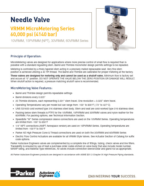
Principle of Operation:MicroMetering valves are designed for applications where more precise control of small flow is required than is possible with a standard regulating stem. Barrel and Thimble micrometer design permits settings to be repeated.Metering is controlled by a finely tapered stem acting in a precisely mated replaceable seat. Very fine stemposition is achieved utilizing a 40 TPI thread. The Barrel and Thimble are calibrated for proper metering at the factory.These valves are designed for metering only and cannot be used as a shutoff valve. Minimum flow is factory set and occurs at “0” position. DO NOT OPERATE THE VALVE BELOW THE ZERO POSITION OR DAMAGE WILL RESULT. When shutoff action is required, a pressure matching shutoff valve is recommended.MicroMetering Valve Features:• Barrel and Thimble design permits repeatable settings • Barrel divisions every 0.025"• 25 Thimble divisions, each representing 0.001" stem travel. One revolution = 0.025” stem travel.• Operating Temperatures vary per model but can range from -100° to 800°F (-73° to 427°C)• UNS S31600 cold worked type 316 stainless steel body. Stem and seat are cold-worked type 316 stainless steel.• Packing below stem threads is PTFE for the 10VRMM, 15PVRMM and 30VRMM valves and nylon-leather for the 60VRMM. For packing options, see Technical Information Section.• Speedbite “W” Series compression sleeve connections are used on the 10VRMM Series. Operating temperatures are limited from -100° to 650°F• 1/4" NPT connections (ANPT Aerospace version) are used on 15PVRMM Series. Operating temperatures are limited from -100°F to 400°F• Parker AE High Pressure Cone & Thread connections are used on both the 30VRMM and 60VRMM Series • Electric Flow Control Actuators are available for all VRMM Style Valves. See Actuator Section of Catalog for suffix code options.Parker Autoclave Engineers valves are complemented by a complete line of fittings, tubing, check valves and line filters. Traceability is ensured by use of heat a purchase order codes etched on valve body that also include model number, MAWP rating, and Material Type references. All valves include connection sleeve/collar and gland nut as appropriate.All Parker Autoclave Engineers products are designed in accordance with ASME B31.3 Chapter IX High Pressure Piping standards.Needle ValveVRMM MicroMetering Series 60,000 psi (4140 bar)10VRMM, 15PVRMM (NPT), 30VRMM, 60VRMM Series2Needle Valves: VRMM MicroMetering Series 02-0115SE 0521MicroMetering Series:Pressures to 60,000 psi (4137bar)Notes** For complete temperature ratings see pressure/temperature rating guide in Technical Information section .Valve Packing Options:Standard Parker Autoclave Engineers 10VRMM, 15PVRMM and 30VRMM Series valves with PTFE packing may be operated to 450°F (232°C). 60VRMM series valves with nylon/leather/nylon packing may be operated from 40ºF (4ºC) to 230ºF (110ºC).*TG Standard valve with PTFE glass packing -100° to 600°F (-73° to 316°).GY Standard valve with graphite braided yarn packing to 32° to 800°F (0° to 427°).B Cryogenic trim materials and PTFE packing required when below 0°F (-18°C) to -100°F (-73°C).Note: *60VRMM valves with -TG option supplied with PEEK/PTFE Glass/PEEK packingParker Autoclave Engineers does not recommend Low Pressure Speedbite sleeve connections below -100°F (-73°C) or above 650°F (343°C). NPT Pipe Connections can be used from -100° to over 400°F (-72 to 204°C) (dependent on sealant temperature range). See needle valve options for stem and seat coating for erosive service.Generalized Flow Coefficient Curves (C v )% of rated C vS t e m T r a v e l : I n c h e s (m m )0.001 0.002 0.003 0.0040.175(4.45) 0.150(3.81) 0.125(3.18) 0.100(2.54) 0.075(1.90) 0.050(1.27) 0.025(.64) 0MicroMetering (VRMM) Series Flow CurveNPT valve option will not have connection collar and gland nut as shown above.15PVRMM “NPT” version shown above3Needle Valves: VRMM MicroMetering Series 02-0115SE 0521Ordering Guide:For complete information on available stem types, optional connections and additional valve options, see Needle Valve Options section or contact your Sales Representative. VRMM Series valves are furnished complete with connection components, unless otherwise specified.Material of Construction:Basic Repair Kits for 316 SS Material:G - Packing Gland mounting hole drill size • G1 - Bracket mounting hole size • H* - Dimension is with stem in closed positionAll dimensions for reference only and subject to change • For prompt service, Parker Autoclave stocks select products. Consult factory.4Needle Valves: VRMM MicroMetering Series 02-0115SE 0521Panel Hole Sizes:*10VRMM Valve has only one mounting screw. Dimension shown is from stem center to panel hole center.10VRMM Thimble must be removed to mount on panel.Needle Valve Panel MountNotesNPT Pipe Thread Connections:NPT threads must be sealed using a high quality PTFE tape(3 wraps minimum) and/or thread sealant paste product suitablefor process temperature.Refer to thread sealant manufacturer’s instructions forapplication instructions. A good thread lubrication product(metal flake style) capable of process temperatures is also necessary to prevent thread galling.Sealing performance may vary based on many factors such as pressure, temperature, media, thread quality, thread material,proper engagement, and proper use of thread sealant.End user should limit the number of times an NPT fitting is assembled and disassembled as thread deformation during assembly will result in deteriorating seal quality over time.5Needle Valves: VRMM MicroMetering Series 02-0115SE 05216Needle Valves: VRMM MicroMetering Series 02-0115SE 0521High Temperature Extension:Required for extreme temperatures-HTHigh Temperature (over 600°F to 800°F maximum)Needle Valve Clam Shell Handle Lockout:(order separately using part numbers shown below, padlock not included)Clam Shell Handle locks are provided to lockout valves in open or closed position preventing unauthorized personnel from actuating valve during shutdown or emergency situations.This clamshell design is available in four (4) sizes dependent on handle length:P/N AE004855 – 1" to 2.5" handle length P/N 90088 – 2.5" to 5.0" handle length P/N 90194 – 6.5" to 10" handle lengthP/N AE004350 – 8" to 13" handle lengthValve Options:(For Actuator Options please reference specific Actuator brochure)Electric Valve Actuators:Parker Autoclave Engineers has developed an electric actuator capable of fine, multi-turn, control.This actuator is designed specifically for our VRMM Series valves to facilitate remote control of these high pressure low flow metering valves. 4-20mA (-C4 suffix) or 0-10VDC (-C10 suffix) control signal options areavailable.NOTES:7 Needle Valves: VRMM MicroMetering Series 02-0115SE 0521! CAUTION !Do not mix or interchange component parts or tubing with those of other manufacturers. Doing so is unsafe and will void warranty.Parker Autoclave Engineers Valves, Fittings, and Tools are not designed to interface with common commercial instrument tubing and are designed to only connect with tubing manufactured toParker Autoclave Engineers AES specifications. Failure to do so is unsafe and will void warranty.Offer of SaleThe items described in this document are available for sale by Parker Hannifin Corporation, its subsidiaries or its authorized distributors. Any sale contract entered by Parker will begoverned by the provisions stated in Parker's standard terms and conditions of sale (copy available upon request).©2021 Parker Hannifin Corporation | Autoclave Engineers is a registered trademark of the Parker Hannifin Corporation Literature #: 02-0115SE May 2021ISO-9001 CertifiedInstrumentation Products Division Autoclave Engineers Operation 8325 Hessinger Drive Erie, PA 16509-4679Tel: 814 860 5700Fax: 814 860 /ipdInstrumentation Products Division Division Headquarters 1005 A Cleaner WayHuntsville, AL 35805 USA Tel: 256 881 2040Fax: 256 881 5072Parker Hannifin Manufacturing Ltd.Instrumentation Products Division, EuropeRiverside RoadPottington Business ParkBarnstaple, UK, EX31 1NP , UK Tel: 44 1271 313131Fax: 44 1271 373636WARNINGFAILURE, IMPROPER SELECTION OR IMPROPER USE OF THE PRODUCTS AND/OR SYSTEMS DESCRIBED HEREIN OR RELATED ITEMS CAN CAUSE DEATH,PERSONAL INJURY AND PROPERTY DAMAGE.This document and other information from Parker Hannifin Corporation, its subsidiaries and authorized distributors provide product and/or system options for further investigation by users having technical expertise. It is important that you analyze all aspects of your application and review the information concerning the product or system in the current product catalog. Due to the variety of operating conditions and applications for these products or systems, the user, through its own analysis and testing, is solely responsible for making the final selection of the products and systems and assuring that all performance, safety and warning requirements of the application are met. The prod-ucts described herein, including without limitation, product features, specifications, designs, availability and pricing, are subject to change by Parker Hannifin Corporation and its subsidiaries at any time without notice.Needle Valves: VRMM MicroMetering Series 02-0115SE 0521Parker WorldwideNorth AmericaUSA – Corporate, Cleveland, OH Tel: +1 256 896 3000USA – IPD, Huntsville, AL Tel: +1 256 881 2040*****************USA – IPD, (Autoclave), Erie, PA Tel: +1 814 860 5700*******************CA – Canada, Grimsby, Ontario Tel +1 905-945-2274*********************South AmericaAR – Argentina, Buenos Aires Tel: +54 3327 44 4129 ******************BR – Brazil, Diadema, SP Diadema, SPTel: +55 11 4360 6700******************CL – Chile, Santiago Tel: +56 (0) 2 2303 9640******************MX – Mexico, Toluca Tel: +52 722 275 4200*******************Asia PacificAU – Australia, Dandenong Tel: +61 (0)2 9842 5150******************************CN – China, Shanghai Tel: +86 21 2899 5000*****************************HK – Hong Kong Tel: +852 2428 8008IN – India, MumbaiTel: +91 22 6513 7081-85ID – Indonesia, Tangerang Tel: +62 2977 7900********************JP – Japan, Tokyo Tel: +(81) 3 6365 4020******************KR – South Korea, Seoul Tel: +82 2 559 0400*******************MY – Malaysia, Selangor Tel: +603 784 90 800*******************SG – Singapore,Tel: +65 6887 6300*******************TH – Thailand, Bangkok Tel: +66 2 186 7000*********************TW – Taiwan, Taipei Tel: +886 2 2298 8987*************************VN – Vietnam, Hochi Minh City Tel: +848 382 508 56**********************Europe, Middle East, AfricaAE – UAE, Dubai Tel: +971 4 812 7100********************AT – Austria, Wiener Neustadt Tel: +43 (0)2622 23501-0*************************AT – Eastern Europe, Wiener Neustadt Tel: +43 (0)2622 23501 900****************************AZ – Azerbaijan, Baku Tel: +994 50 2233 458****************************BE/LU – Belgium, Nivelles Tel: +32 (0)67 280 900*************************BG – Bulgaria, Sofia Tel: +359 2 980 1344**************************BY – Belarus, Minsk Tel: +48 (0)22 573 24 00*************************CH – Switzerland, Etoy Tel: +41 (0) 21 821 87 00*****************************CZ – Czech Republic, Klecany Tel: +420 284 083 111*******************************DE – Germany, Kaarst Tel: +49 (0)2131 4016 0*************************DK – Denmark, Ballerup Tel: +45 43 56 04 00*************************ES – Spain, Madrid Tel: +34 902 33 00 01***********************FI – Finland, VantaaTel: +358 (0)20 753 2500*************************FR – France, Contamine s/Arve Tel: +33 (0)4 50 25 80 25************************GR – Greece, Athens Tel: +30 210 933 6450************************HU – Hungary, Budapest Tel: +36 223 885 470*************************IE – Ireland, DublinTel: +353 (0)1 466 6370*************************IT – Italy, Corsico (Ml)Tel: +39 02 45 19 21***********************KZ – Kazakhstan, Almaty Tel: +7 7273 561 000****************************NL – The Netherlands, Oldenzaal Tel: +31 (0)541 585 000********************NO – Norway, Stavanger Tel: +47 66 75 34 00************************PL – Poland, Warsaw Tel: +48 (0)22 573 24 00************************PT – Portugal, Leca da Palmeira Tel: +351 22 999 7360**************************RO – Romania, Bucharest Tel: +40 21 252 1382*************************RU – Russia, Moscow Tel: +7 495 645-2156************************SE – Sweden, Spånga Tel: +46 (0)8 59 79 50 00************************SK – Slovakia, Banská Bystrica Tel: +421 484 162 252**************************SL – Slovenia, Novo Mesto Tel: +386 7 337 6650**************************TR – Turkey, Istanbul Tel: +90 216 4997081************************UA – Ukraine, KievTel: +48 (0)22 573 24 00*************************UK – United Kingdom, Warwick Tel: +44 (0)1926 317 878********************ZA – South Africa, Kempton Park Tel: +27 (0)11 961 0700*****************************。
- 1、下载文档前请自行甄别文档内容的完整性,平台不提供额外的编辑、内容补充、找答案等附加服务。
- 2、"仅部分预览"的文档,不可在线预览部分如存在完整性等问题,可反馈申请退款(可完整预览的文档不适用该条件!)。
- 3、如文档侵犯您的权益,请联系客服反馈,我们会尽快为您处理(人工客服工作时间:9:00-18:30)。
Item 2 3 4 4 7 8
Spare part Motor lever Connecting rod Coupling, comp. right Coupling, comp. left Gear motor with torque motor Clevis, comp.
Wear part
Order no. 22D000D00041 22D000E02617 22D000B02611 22D000B02612
ANNEX FLOW CONTROL GATE
8/8
IBAU HAMBURG
22D030X01441
Fig. 14: Flow control gate with motor actuator, coupling and switch box
ANNEX FLOW CONTROL GATE
5/8
IBAU HAMBURG
Pneu. actuator, Size 300, Drawing no.: 22D030B00099
Item 2 12 14 14 15
Spare part Clevis, comp. Pneu. cylinder * Coupling, comp. right Coupling, comp. left Control valve
WD07508 From 22D030X02978 22D000B02611 22D000B02612 From 22D030 X02978
ANNEX FLOW CONTROL GATE
7/8
IBAU HAMBURG
Pneu. rotary actuator with 5/3-way valve, Size 300, Drawing no.: 22D030B00157
Item 8 9 11 12
Spare part Rotary actuator, anti-clockwise closing Rotary actuator, clockwise closing 5/3-way valve, anti-clockwise closing 5/3-way valve, clockwise closing
Wear part
Order no.: From 22D030X03082 From 22D030X03081 22D000C00117 22D000C00114 From 22D030X03082 From 22D030X03081
Fig. 16: Pneumatically-actuated flow control gate with rotary actuator with electro-pneumatic control device
Standard device, Size 300, Drawing no.: 22D30A09723
Item 2 4 6 7 9 20 21 22 24 30
Spare part Roller
Spacer
O-ring * Shaft Aeration pad (optional)
Wear part
ANNEX FLOW CONTROL GATE
3/8
IBAU HAMBURG
Item 31 32 33 34
Spare part Switch box, comp. * Potentiometer PW 620 Potentiometer PW 45 D Rotary angle transducer
Wear part
Order no. From 22D030X03086 From 22D030X03085 From 22D030X03086 From 22D030X03085
Fig. 17: Pneumatically actuated flow control gate with rotary actuator and 5/3-way valve
Fig. 15: Pneumatically actuated flow control gate with pneumatic piston, coupling and switch box
ANNEX FLOW CONTROL GATE
6/8
IBAU HAMBURG
Pneu. rotary actuator with positioner, Size 300, Drawing no.: 22D030B00155
ANNEX FLOW CONTROL GATE
2/8
IBAU HAMBURG
Fig. 12: Flow control gate standard type (here with roller type 'A') * with aeration pad (optional)
Options for the switch box
Wear part
Order no.
22D030X01584 22D030X02238 22D030X03109
Fig. 13: Switch box
ANNEX FLOW CONTROL GATE
4/8
IBAU HAMBURG
Motor actuators, Size 300, Drawing no.: 22D030B00094
Annex Flow control gate
TABLE OF CONTENTS
Page
Spare parts / Wear parts
Size 300
2
© 02/2005
ANNEX FLOW CONTROL GATE
1/8
IBAU HAMBURG
Spare parts / Wear parts
When ordering spare parts, take care to accurately indicate the data on this type plate.
(Fig. 12 - 17)
* Attention - all parts marked with '*' differ for the increased temperature version from the standard version (see also par. 1.5.0). When ordering spare and wear parts for increased temperature versions, indicate the specified temperature range of the flow control gate.
Item 8 9 10 11 12 13
Spare part Rotary actuator, anti-clockwise closing Rotary actuator, clockwise closing Hand lever, left-handed design Hand lever, right-handed design Control device, anti-clockwise closing Control device, clockwise closing
Roller gasket * Bushing *
Deflector Shaft sealing ring *
Felt ring *
Order no. 007101B M 22D030A02589 22D000E02590 22D000E02591 22D030D10722 22D030X00425 22D030X01710 22D000E03144 22D030D02587 22D030C11982